Week 10 - Challenge 1- Attachment Feature Creation (Ribs & Screw Boss)
DOOR HANDLE
As per the given class A surface link, I have converted the sp file into CATPart file and then started to work.
Firstly I have made class A surface to a geometrical set named Class A and made the surface to Publication.
Then added new geometrical set named Tooling axis and start to create the tooling axis. For that I visualised the direction which our tooling axis may take in the X, Y AND Z components and found that it is appropriate in the Y direction and drawn the line through that direction. Then made checked the draft analysis and made it as my tooling axis and added to Publication.
Then I added a new geometrical set named B surface and started to work on my need B surface. For that , I just offsetted my class A surface to 2.5 mm inwards. Then I used multisectionsurface tool to clear the patching areas in the offsetted surface. Thus I got my B surface and i added it to Publication. Then I extrapolated my B surface a little for the easy trimming later.
Then I created new geometrical set named C surface and started to work on the C surface. For the creation of the C surface, I have taken the boundary of the Class A and sweeped it to 90 degress downward with reference to class A surface to about 3 mm. Thus I got my required C surface too.
Then I created new geometrical set named Final trim and done the trimming together with Class A and C surface.
Then later the trimmed portion with B surface. Thus I got my required design of the part which was hollow inside. men i added a new part body and closed the hollow part using the part design feature tool Close surface).
surface to about 3 mm. Thus I got my required C surface too.
Then I created new geometrical set named Final trim and done the trimming together with Class A and C surface.
Then later the trimmed portion with B surface. Thus I got my required design of the part which was hollow inside.
Then I added a new part body and closed the hollow part using the part design feature tool( Close surface).
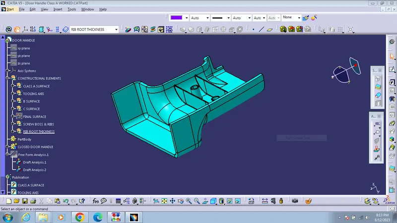
Then I again jumped to generative shape design and created new geometrical set and named it as Screw boss and Ribs. Then I drawn sketches for the creation of ribs and screw bosses by creating an axis in the point in the base surface. After creating all the sketches in one stretch, I extracted each of them. Then I extruded the lines for the ribs in the tooling direction with the required height which is less than 5*2.5mm.
Then I moved to part design and Thickened the extruded surfaces to 1 mm which is 0.4*2.5 mm) after creating them into a body named Ribs. Then I union trimmed it with the close body by keeping the required sides of the part. Thus I got my Ribs.
Then I created a new part body and padded the four circle I have extracted and removed one circle from another inorder for the screw holes to provide. And finally I added it with the close body.
Then I started to give the draft in all the sides required drafting with .5 degrees by keeping the tooling axis as the pulling direction.Then I given the fillets as .313 mm (125-2.5 mm) to all the sharp edges. Then I measured the thickness at the top which is greater than 0.75 mm.
Then I created a new geometrical set named Root Rib Thickness and started to medssure my Rib Root thickness. For that I jumped to generative part design and created a point and a plane with respect to a curve. And checked the intersection line of the plane with the part body designed including ribs and screwbosses which re drafted and filleted). Then drawn a tritangent circle in the junction of the ribs and checked the diameter (2.5*1.3).
Thus I confirmed that my designed ribs and Screw bosses have cleared all the design criterias required.
Then I checked the final draft analysis with maximum deviation as 45 degrees.
Thus I completed my challenge.