Week 12- Final project
INTRODUCTION
The door trim panel of a car is the interior parts of the door which contains the most controls and decorative parts, the main components of interior door panel of a car consist of the following parts
- Arm rest
- Map pocket
- Bottle Holder
- Door lower substrate
METHODOLOGY
The procedure followed for creating the Interior Door trim panel is the same as followed in the OEMs and Tier-1 companies. First, the Class A surface is divided into sub-parts and the geometrical sets are rearranged. Then tooling axis, improvement of Class A surface, Class B surface, Class C surface, and B-side attachments are created. After this Draft analysis is performed to check the manufacturing feasibility.
- Creation of Tooling Axis:
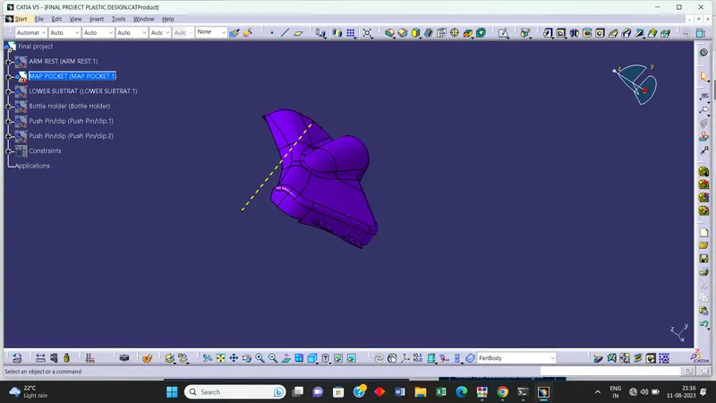
Tooling axis is nothing but the direction in which the Core and Cavity Opens and Closes.Design Engineer works is to Analyse the Class A Surface and find out the best possible tooling direction keeping in mind all the draft angle is with respect to the tooling axis so that the Component can be easily ejected from the moulds as well as all tooling axis is created by using point & direction method
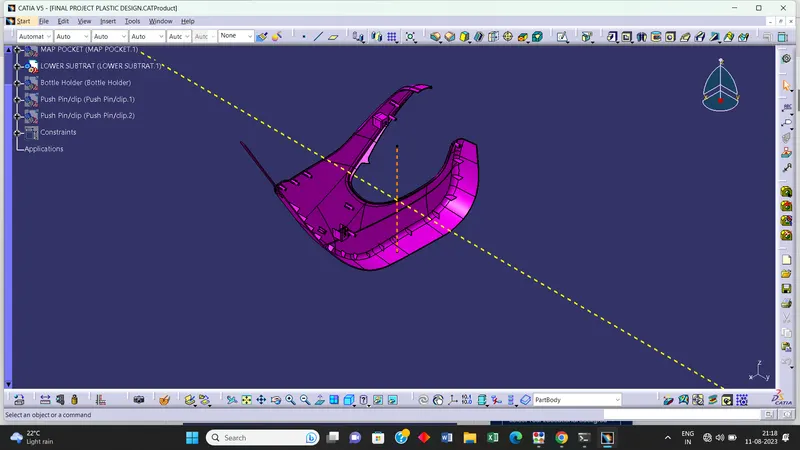
LOWER SUBSTRATE -
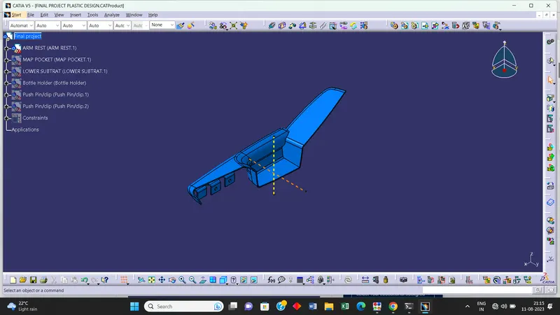
DOOR ARM REST -
MAP POCKET -
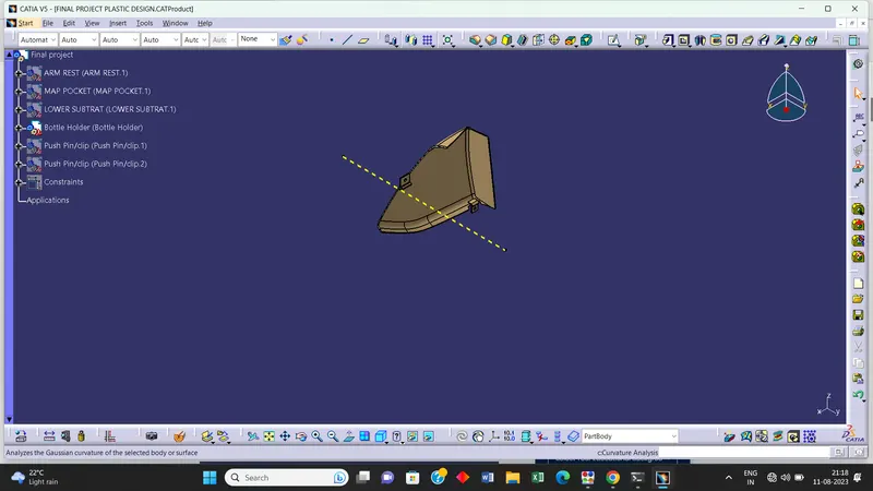
BOTTLE HOLDER -
PUSH PIN -
- CLASS B - SURFACE
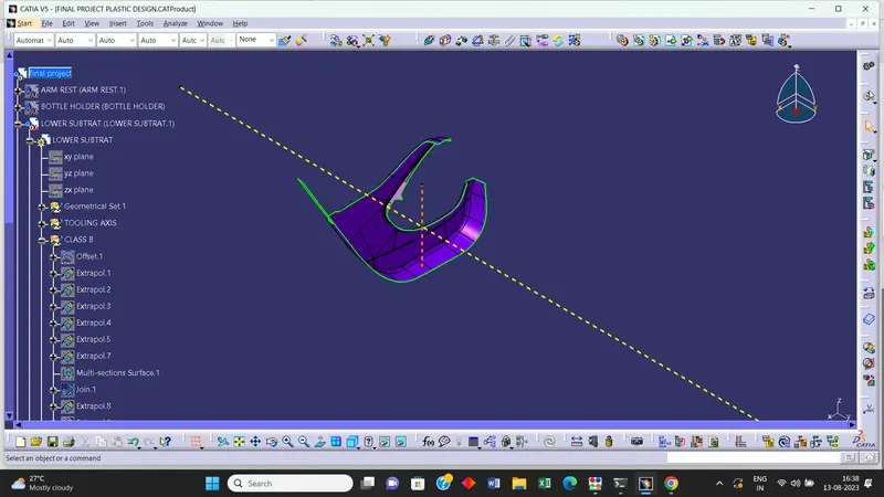
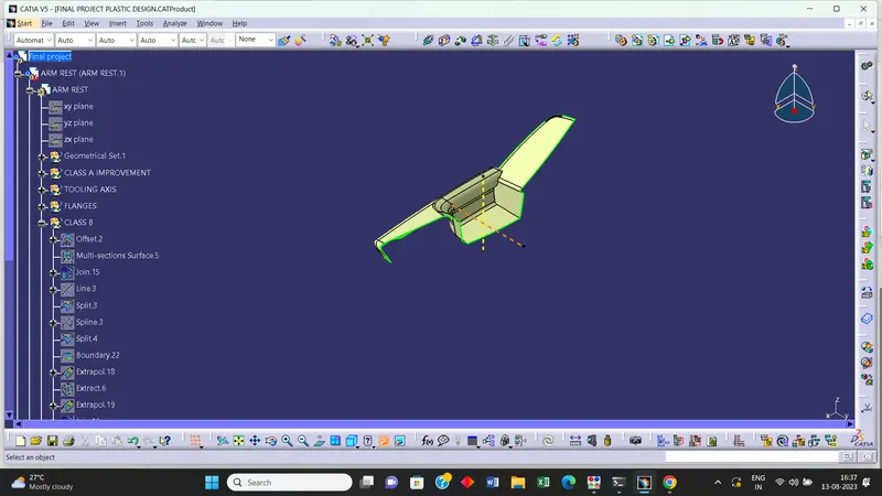
1] Creating a Class B surface with the reference of Class A surface.
2] Make a offset of 2.5 mm with the help of mastersection.
3]The final class B surface must have the edge fillets similar to the class A and fillets must be given properly with a thought of maintaining same thickness throughout avoiding the flow line defects.
LOWER SUBSTRATE -
DOOR ARM REST -
MAP POCKET -
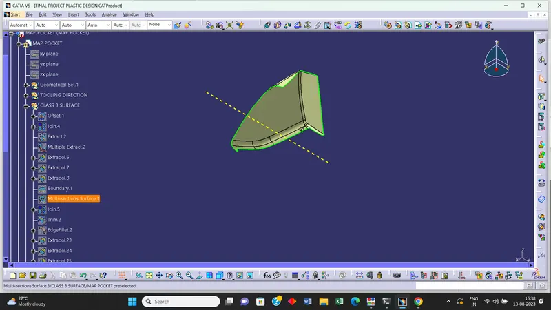
BOTTLE HOLDER -
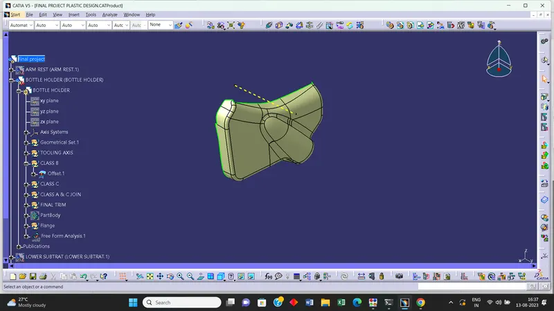
CREATION OF CLASS-C SURFACE
1] The class C surface is the middle portion of the class A and class B surfaces.
2]The class A surface's boundary is taken as profile (guide curve) and then tooling axis created is taken as direction of the sweep in subtype draft direction.
3]The final trim is obtained by trimming the class B with the class C surface.
LOWER SUBSTRATE -
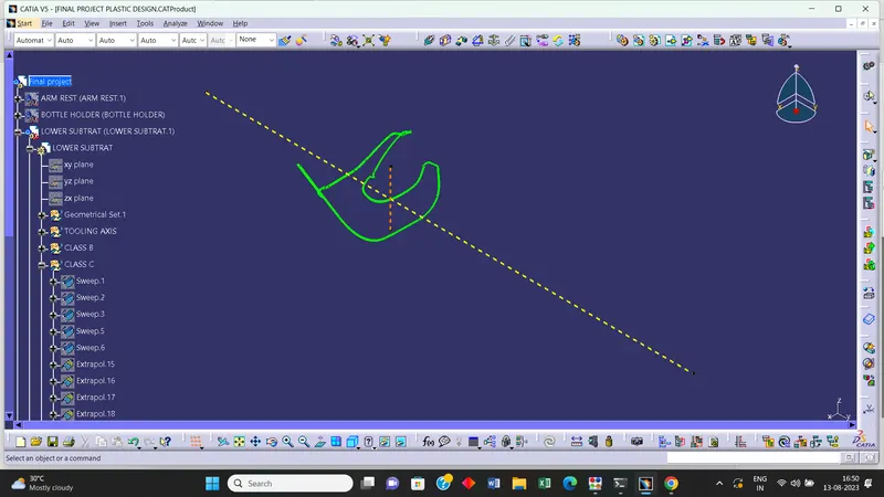
DOOR ARM REST -
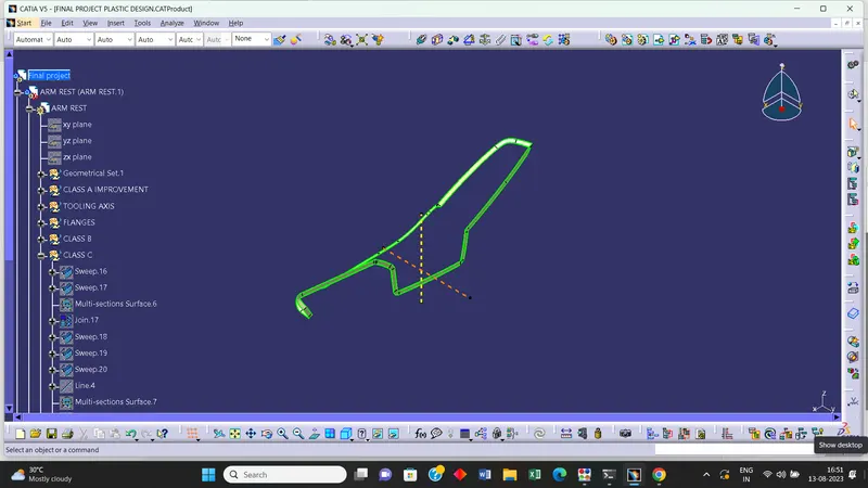
MAP POCKET -
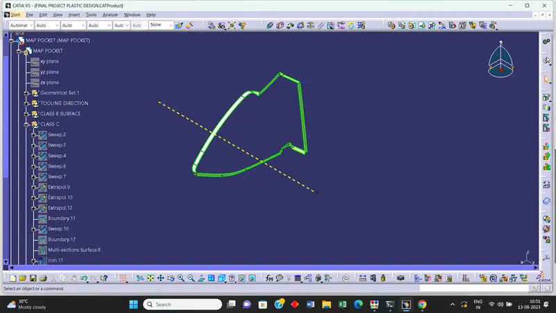
BOTTLE HOLDER -
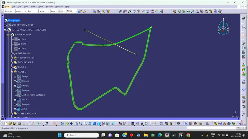
- B - Side Feactures Creation
1] Heat Stakes: It is the process used to join two or more parts by deformation of the plastic by applied heat and pressure, for a certain time. The applied heat melts the extruded heat stakes on the primary component and it settles on the secondary component. After cooling both the components are firmly joined.
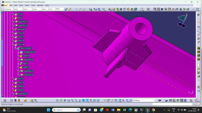
2] Ribs - Ribs provide a economical stiffness and strength in molded parts without increasing overall wall thickness.They also facilitate.
ii) Rib designs includes.
iii) thickness, quantity, height , manufacturibility and location.
iv)The ribs are used as locating and arresting in the assembly as locators.
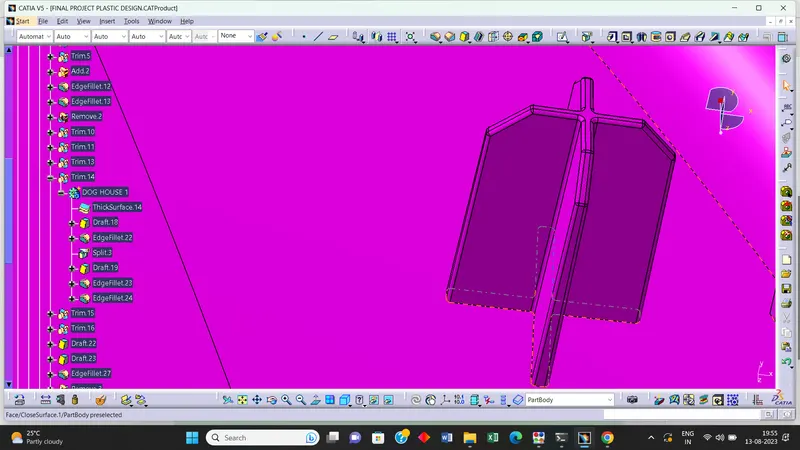
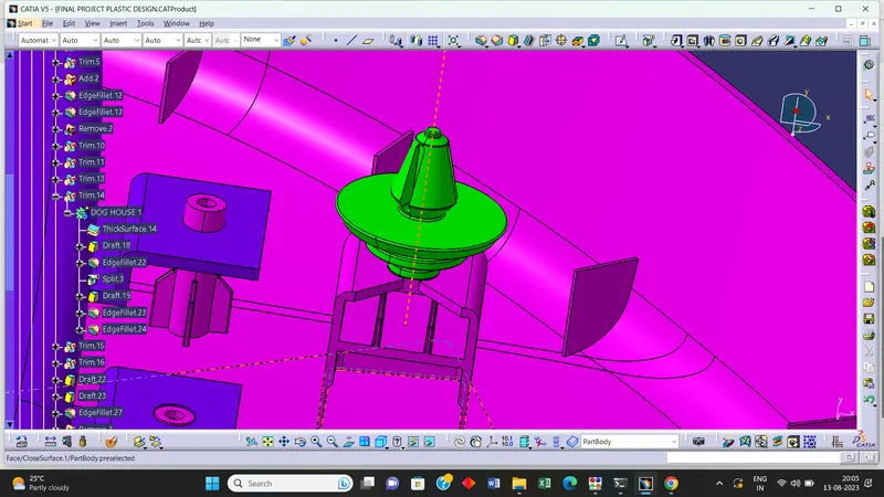
3] Dog House - i) The dog house is an engineering feature used in the plastic trim design. Dog houses are used as supporting features
ii) Many times the screw bosses or push pins need to be given extra length in order to perfectly assemble with other components.
iii) Design engineer can't directly increase their height, as all the components are made with proportion to the width and thickness of the component
iv) This can cause sink marks on the component. Hence we provide a dog house wherever necessary and place our engineering feature above it for perfect finish of the component.
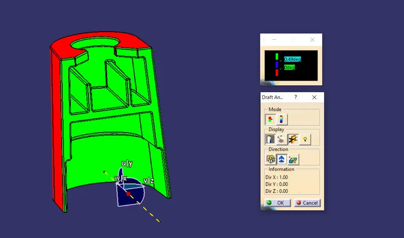
Design Rules For Dog House:
- Sink Saver Thickness = 0.4 * Thickness of the Dog House
- Length of Sink Saver = 3 mm to 6 mm
- Upper Width = 12 mm
- Outer Draft = 1.5 deg minimum
- Draft for lifter Axis = 0.5 deg.
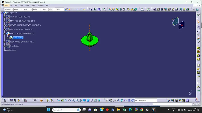
4) Push Pin Clip
i) It is used to attach to parts by pushing them together using the clip.
ii) It is usually placed on the Dog House to hold the clip firmly.
DRAFT ANALYSIS OF THE COMPONENTS :
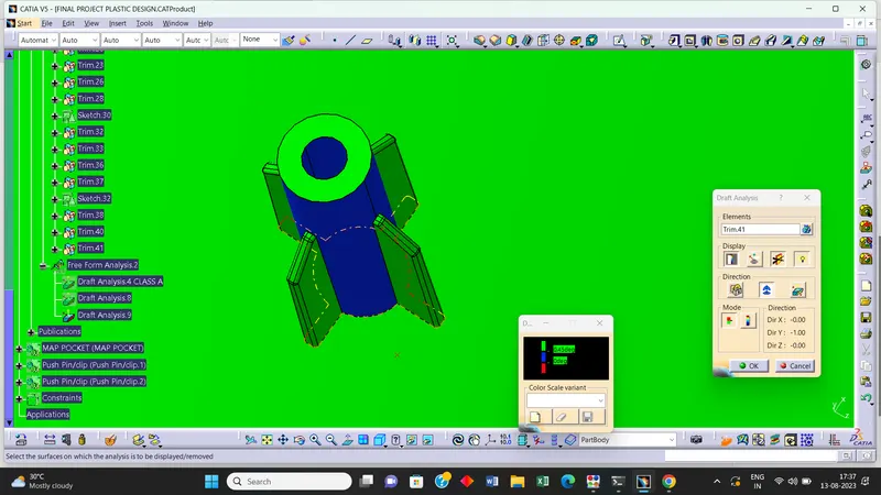
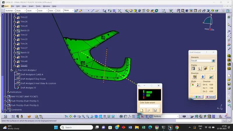
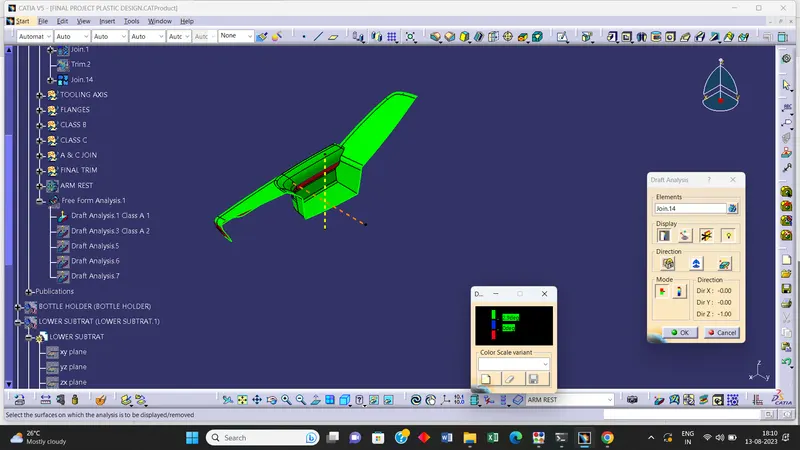
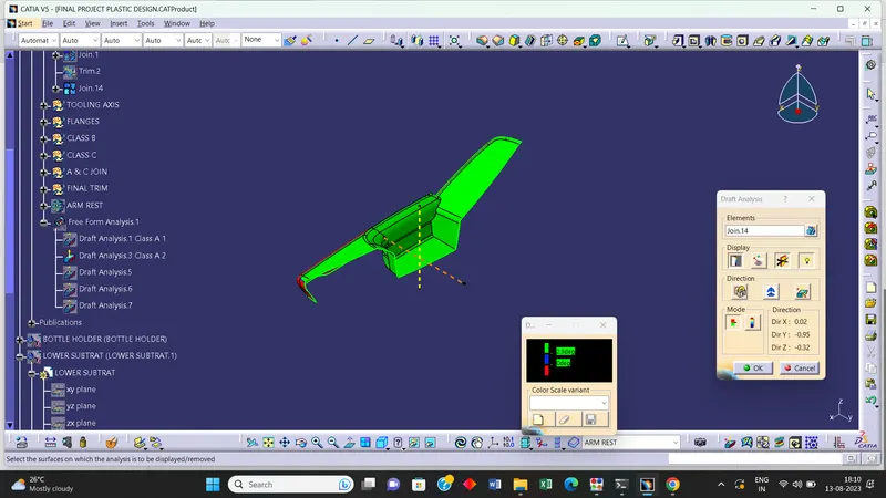
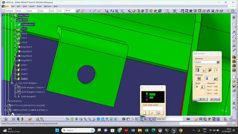
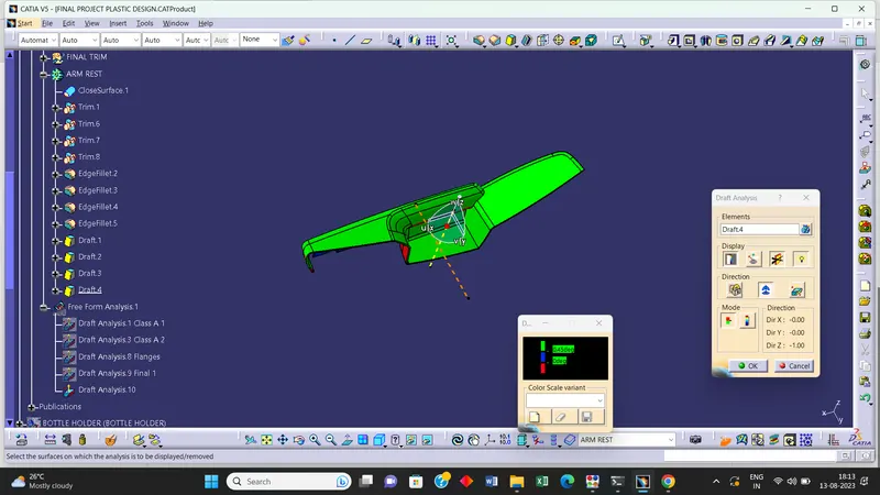
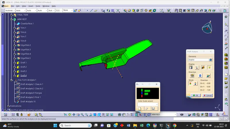
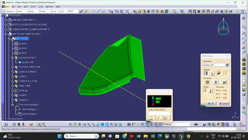
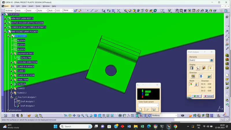
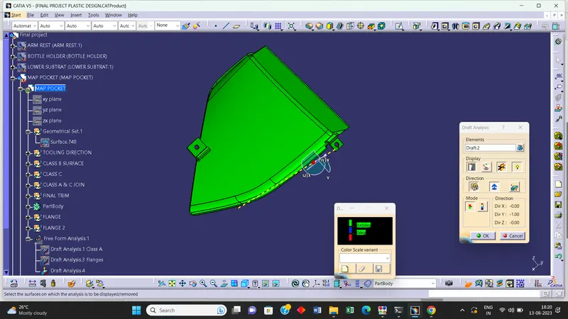
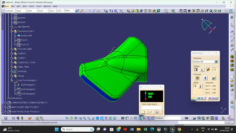
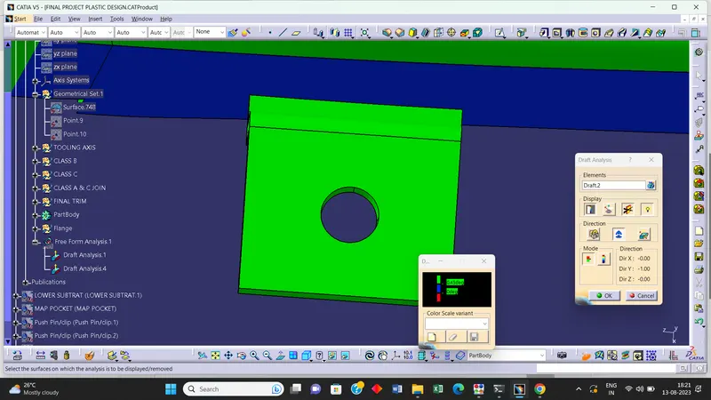
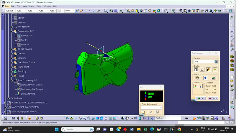
1] Draft analysis is done to check whether that the designed part is manufacturable or not based on its draft condition as per industrial standards .
2] A draft analysis is used to see if the draft of a part is sufficient for the molding process and if the part will separate correctly from the mold.
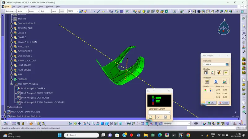
3] Here both class A and closed body are given the minimum draft as 3 degrees.
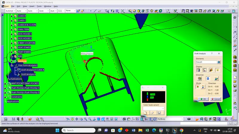
4] The attachment feature are given draft of 0.5 degrees.
Steps -
i] First check the colour mode and select material mode.
ii] Click on Insert >> Analysis >> Feature Draft Analysis.
iii] Draft analysis window will be opened having three sections - Mode , Display and Direction.
iv] In the Display section select the compass and drag it onto your component. Place it along the tooling axis
v] Lock the direction of the draft.
vi] Another window will be displaying ranges of draft on the component.
vii] The ranges are - Green for more than zero , Red for zero and Blue for negative draft value.
viii] Assign the lower limit as 3 deg to the Green range from the value edition dialogue box.
ix] Once you do it, click on the component to see the results.
- LOWER SUBSTRATE -
Class A surface
Dog House
Heat Stake & Locators
Final Componant -
- DOOR ARM REST -
Class A Surface
Flanges
Final Componant -
- MAP POCKET -
Class A surface
Flanges
Final Componant
- BOTTLE HOLDER -
Class A surface
Flanges
Final Componant
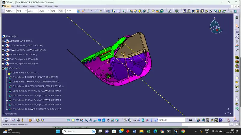
- Final Assembly