Week 12- Final project
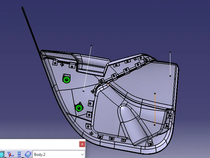
1)To design the Lower Door Trim of the door from the given Class-A Surface in Catia -V5.
Door Trim is the interior component attached to the inferior side of the door. It's a vital component which provides aesthetic look to the interior of the car and also provides features and functions for the passengers. In this project we are going to design the lower portion of the door trim from the given Class-A Surface. Also we would be designing the B-Side Features on the component by following the industry standards and design rules.
First we need to creat real tooling axis, for that we have to intersect the surface A in x and y axis then we got two dummy axis then we have to bisect the two lines in order to get the real tooling axis of surface .
1st we extract the bottom base because we can easily creat the tooling axis in z direction , then creat point on base surface and go for position sketch and select zx and zy plane for creating the dummy aixis
but in this complex model its very difficulty to vislble all parts in one axis. here we choose x axis because we can able to see more parts compare to other axis.
here, we set one point on appropriate edge for creating the tooling axis and creat line .
Tooling Axis - Tooling Axis is the direction in which the component will be ejecting after the molding process is completed. The rules of selecting an optimum direction of tooling axis for any particular component is as follows :-
- The direction of the tooling axis should be clearing the maximum number of portions of the component once the molding process is completed.
- The direction of the tooling axis should be selected such that the number of side cores required should be minimum, as inserting side cores causes a rise in production cost.
Drafting - Draft is the inclination given to any particular plastic component’s cavity walls in order to achieve easy ejection, once the process is completed.
- Consider that the draft angle between the plastic component and the core is zero.
- When the molten plastic inside the cavity cools, it sticks to the walls of the core.
- During such zero draft condition, the ejection of the plastic component causes friction between them which might bring damage to both the core and the component.
- This damage further leads to inefficiency in the production & also affects the product’s surface finish.
- Hence, a minimum of ½ to 1 deg draft is provided to help in releasing the component.
- However 3 deg draft is widely accepted as a norm in the industry.
Creating any component from Class A Surface ( Overview ) -
- Decide a suitable tooling axis direction and create the Tooling Axis.
- Perform Draft analysis for analyzing whether the drafts on the component follow the industry standards.
- Create another surface ( B Surface ) offset to the Class-A Surface. The offset distance should be equal to the thickness of the component.
- Create a C- Surface ‘Sweeping’ the boundary of Class-A -Surface along the Tooling Axis.
- Trim Class- A surface with B-Surface and C Surface to create a closed surface.
- Finally create the solid part from this surface to obtain the desired component.
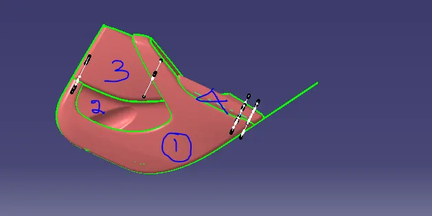
class A of door trim including 4 major part
1-lower substrain
2-bottle holder
3-m packet
4-arm rest
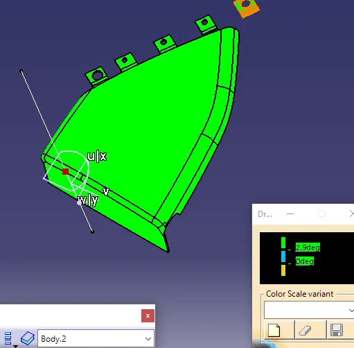
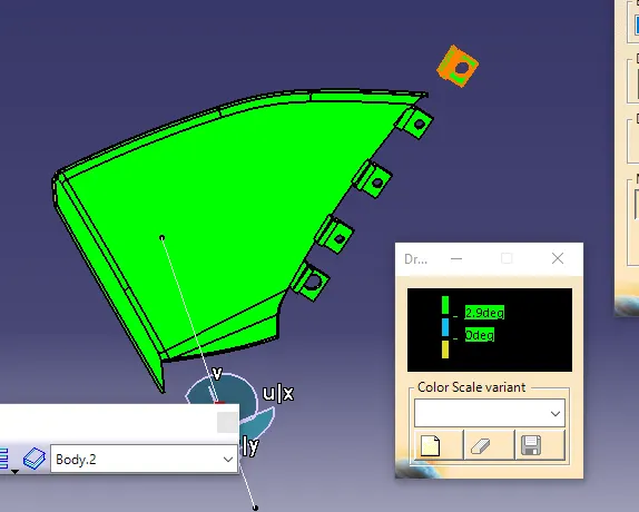
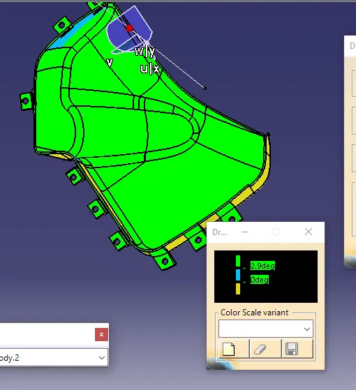
Draft Analysis Of Class-A Surface:
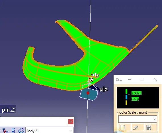
- Draft Analysis is performed on the component in order to check whether the component can be manufactured or not.
MINIMUM DRAFT FOR THE COMPONENT = 3 DEG
LOWER SUBSTRAIN
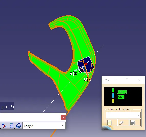
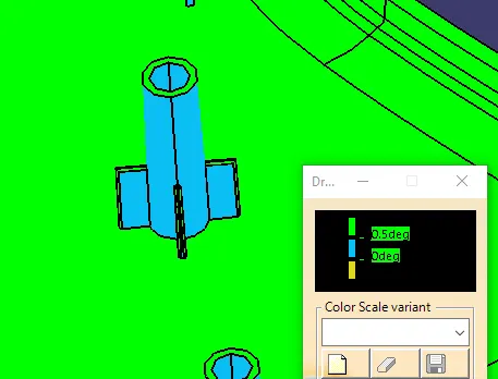
MPOCKET
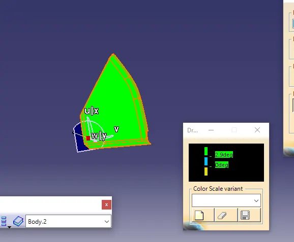
BOTTLE HOLDER
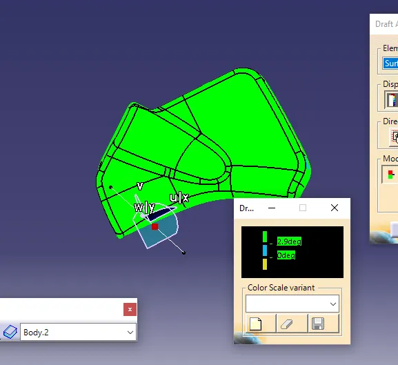
creation of solid part frim calss A
class A surface
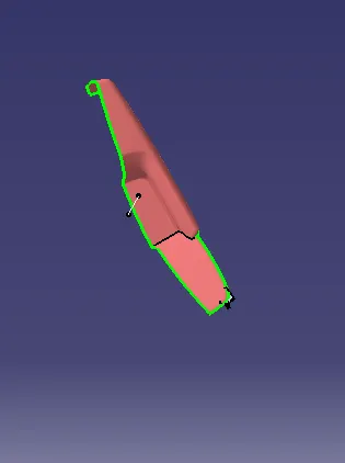
here we can observe the some patches over the class A surface itself, for that we have to improvement the class A surface
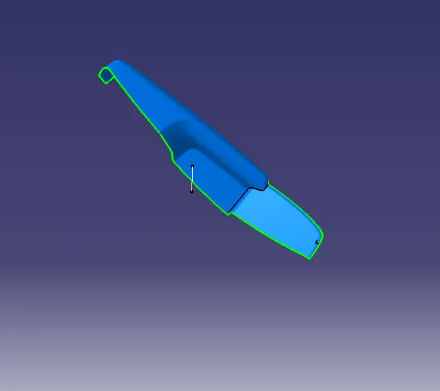
class b surface
offset the surface into2.5mm towords to inside and extract the non connectivity parts from main body
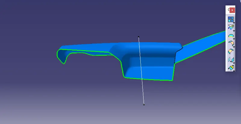
creat of class c surface
surface which has perpendicular to drafting axis then we have to go for drafting with tooling axis and gives 3 degree draft towards to outside
suppose surface which has parrallel to drafting axis then we go for reference with surface option and gives 90 degree for sweeep.
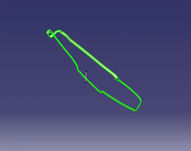
join A and C surface
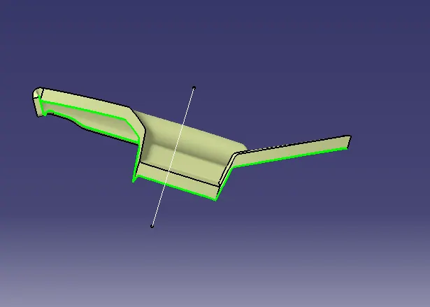
finally trim the class B with join A and C surface
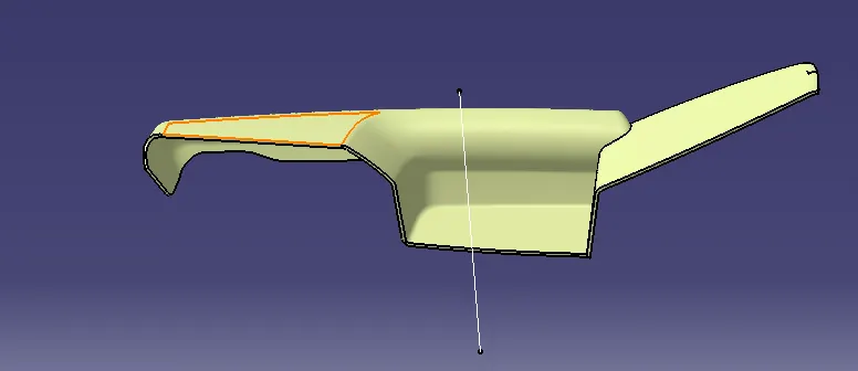
make it closed solid surface using closed surface
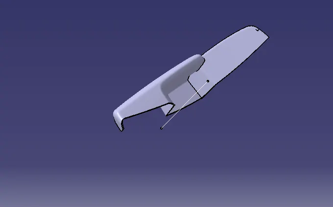
drafting analysis of complite part
arm rest
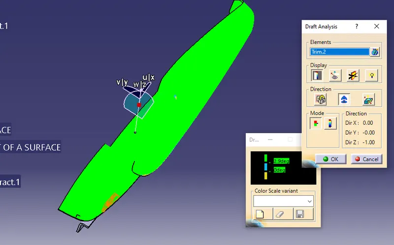
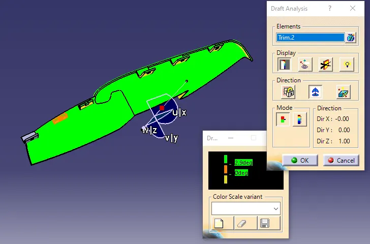
lower substrain
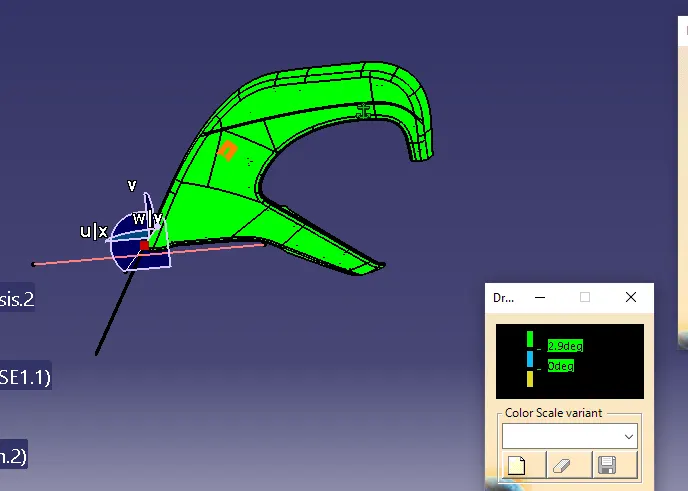
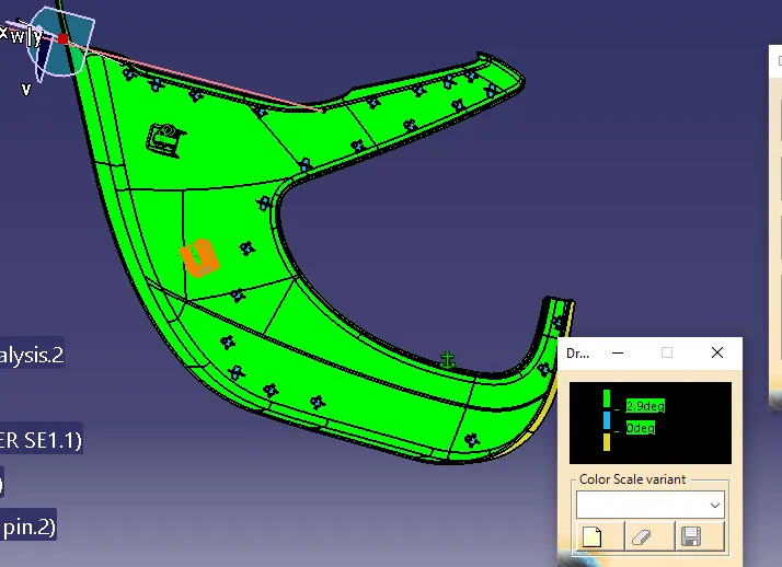
for dog house
Design Rules For Dog House:
Outer Draft = 1.5 deg minimum
- Sink Saver Thickness = 0.4 * Thickness of the Dog House
- Length of Sink Saver = 3 mm to 6 mm
- Upper Width = 12 mm
- Outer Draft = 1.5 deg minimum
- Outer Draft = 1.5 deg minimum
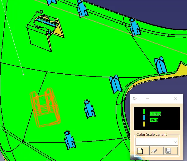
core side drafting
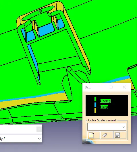
Heat Stakes:
MINIMUM DRAFT = 0.5 DEG
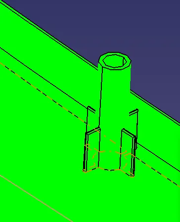
Design Rules For Locators:
- Thickness of the Locator = 0.4*thickness of the component.
- Fillet Radius = 0.25mm
- Draft = 0.5 deg
NOTE: The height of all the locators should be equal.
MPOCKET
BOTTLE HOLDER
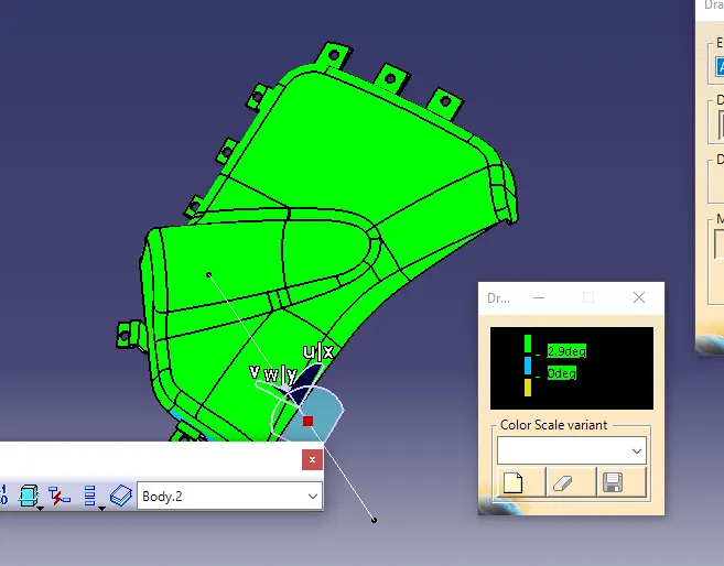
Assemble of aLL parts