Week 12- Final project
*Aim-
- Development of a Door Trim panel
Creation of CAD model considering following inputs as like in OEM and tier1 companies
- a) Class A surface
- b) Nominal thickness : Refer master sections
- c) Attachment strategy :
Find a attachment strategy for the door panel complete work.
Use Push pin with Dog house for Lower substrate – Door panel attachment
Use heat stakes for part to part attachment
*Software Used- CATIA V5
*Indroduction-
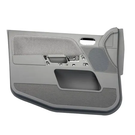
*Door Trim Panel
The door's inner mechanisms and the vehicle's interior are connected by the door panel, as are the passengers within the automobile and the door. They must adhere to a number of design requirements in terms of operation, appearance, and safety. They should also maintain the dashboard's material motif while hiding complex electrical and mechanical parts that control the vehicle's locks, windows, and other amenities. From a straightforward latch and winding mechanism in two parts, the door panel has developed into a more complex enclosure. Currently, doors have an interior full-width panel with speakers, electronic glass, and a central locking system. These panels typically have a foamed core that is wrapped in either plastic or fabrics. Plastics are fundamental.
*Class-A surface-
The Course-A surface is the outermost, best-looking surface of a plastic component. It is also the surface that the designer develops aesthetically as an input component for design work.
*Class-B surface-
The Class-B finish is a high-quality finish with few flaws. The most typical finish for outdoor surfaces is a Class-B finish. It is typically specified on elements and surfaces that are fairly conspicuous, such as external coverings and panels.
*Class-C surface-
Compared to Class-A or Class-B finishes, the Class-C finish allows greater flaws. Class-C specifications are frequently made for interior surfaces that are difficult to see, areas that will be hidden by another part when the component is completed, or surfaces that the customer feels don't require a high level of aesthetic finish.
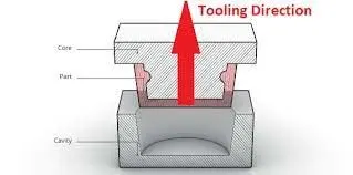
*Tooling Axis-
In moulding, a machine setup is provided to open the mould along what is referred to as the tooling direction. Alternatively put. The mould is made up of two distinct portions (the Core and the Cavity), and the tooling direction essentially determines how the Core or mould pulls apart.
*Draft Analysis-
You can determine whether the section you sketched will be simple to remove using the Draught Analysis tool. Based on colour ranges, this type of analysis locates areas on the examined element where deviations from the draught direction at any given position match to predetermined values. The majority of parts or applications call for a minimum of 1/2 to 1 degree, while 3 degrees is generally regarded as the standard.

1) Creation of tooling axis:-
We must import the model into catia as a product in order to establish tooling axis.
MASTER SECTION DEVELOPMENT.igs file, file=>open, browse.
Given class A surface
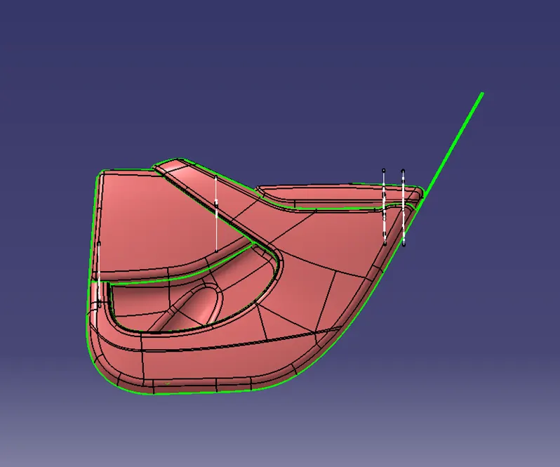
Rear side of the class A with master section
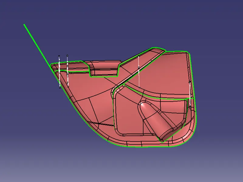
Make a product file, then copy each component into a new part file with the appropriate file name.
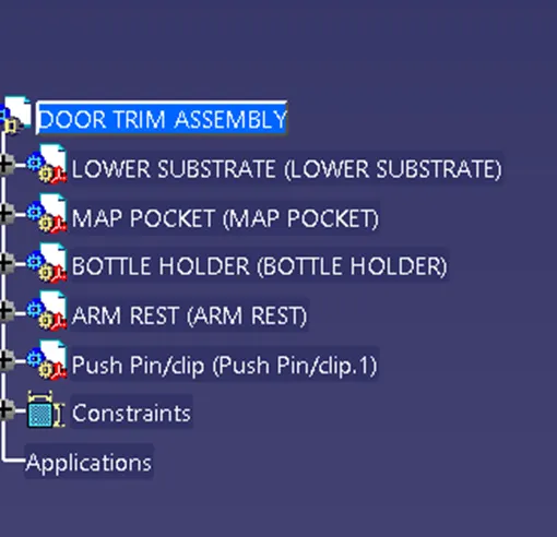
*CREATION OF TOOLING AXIS
Step 1.Insert a geometric set as the first step. Using the point on surface option of the point tool, extract the base surface and make a point in the centre of it. To ensure that all faces are clear for tooling, find a suitable axis to produce.
Step 2.Create an axis system in without selecting the above option. Make a position sketch using the axis system's zy plane as a reference point and the point above.
Step 3.Choose an appropriate plane (zy) and use the project tool's intersect 3d objects option to make two lines. Next, draw two lines that meet at the projection point and the lines on either side of it. Use the bisect option to draw a line. Align the line with the necessary axis. Our Y tooling axis is seen here.
Step 4: Create a position drawing using the xz plane as the reference plane and the projection point as the initial point we produced in order to create the tooling axis about the x direction. Utilise the cut section tool and the projection tool to construct an intersection. Next, draw a line that touches this line.
Step 5: From the starting point, draw a line horizontally with a 5 degree angle limit. To draw a line connecting the lines above, use the bisect option. Our X tooling axis is seen here.
Step 6: Use the bisect option to create a new line between the X and Y tooling lines. This is the necessary Tooling Axis for us. Put this online with the name "tooling axis."
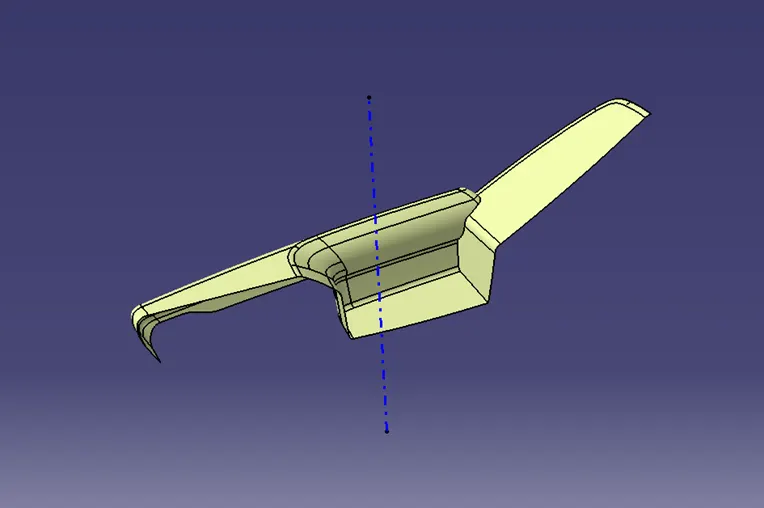
PROCEDURE FOR DRAFT ANALYSIS:
1) Use the Publication from tool option to publish the tooling axis and the component when they have been developed.
2) Select the Feature Draught Analysis tool from the Inserts tool bar.
3) Select the material option under shading after changing the view option to suit your preferences.
4) After aligning it with the tooling axis, select the axis choice from the Draught analysis tools, and then select the lock option to lock it.
5) Change the value of the draught angle to 3. Select Quick Analysis Mode to display the feature using the provided colour scheme. Verify the draught analysis is clear from all angles.
6) Click the lock axis button to unlock it since the generated tooling axis does not clear the draught analysis at the created axis. Now, left-click on the top, rounded part of the axis system to rotate the tooling axis. until the maximum clearance is attained, rotate the axis. Right-click the axis now, then select lock current axis.
7) Use the point and direction (using compass direction) option to draw a line using the initial axis origin and this axis. This is the tooling axis that we need.
8) If we check the ribbed region for draught analysis now, we can see that it has not yet been removed. As a result, we must design a side core tooling axis. Create a line using the point and direction option with the Y direction to accomplish this.
9) Go back and redo steps 1 through 5 to make sure that the last bit that wasn't cleared using the tooling axis was cleared using this axis.
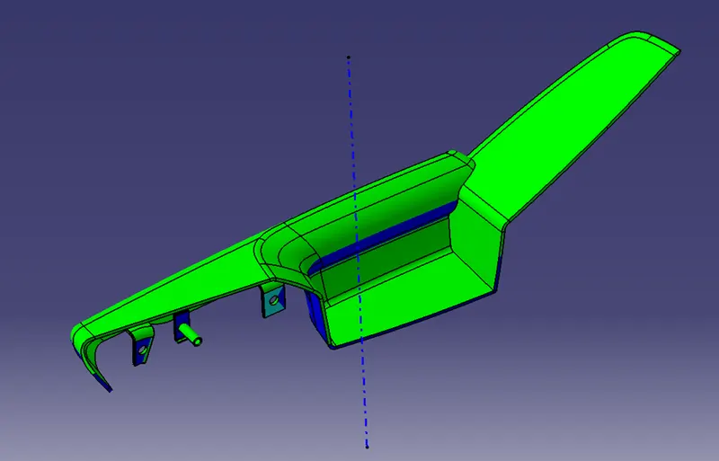
Similarly created tooling axis using same procedures for all other components.
*Tooling axis for lower substrate-
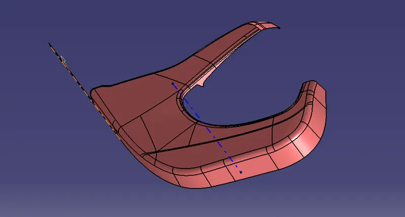
*Tooling axis for Map pocket-
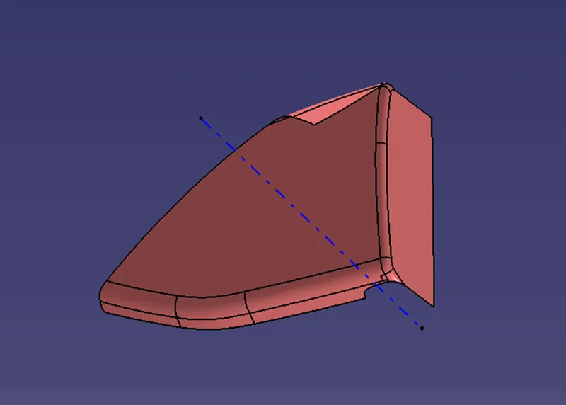
*Tooling axis for BOTTLE HOLDER-
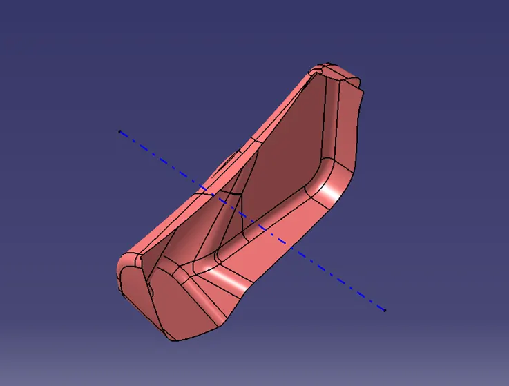
We can see that the CYAN colour patches have a 0 degree draught angle in this image. This might cause issues with ejection during the moulding process. The class A surface must be changed as a result to comply with the draught criteria. As a result, we have developed tooling axes for each component.
2) Creation of class B surface-
Procedure to create class B surface for Lower substrate.
Step 1.To generate an offset of a class A surface, use the offset tool with a distance value of 2.5mm
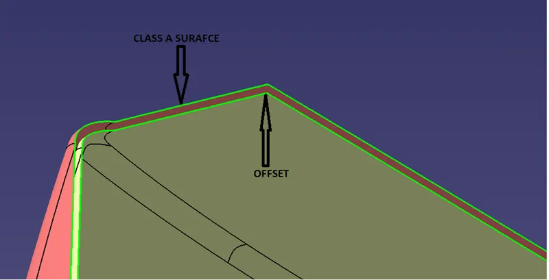
Step 2: This surface's edges were all extended using the extrapolate tool after offsetting. To make sure that the dividing line arrives at B surface, this is done.
Step 3: The multi-section surface option was employed in locations where extrapolation was not possible (Fillet or cusped surfaces).
Step 4: Create a single surface by joining every extrapolated surface and multisection surface.
Hence the class B surface was created for MAP POCKET.
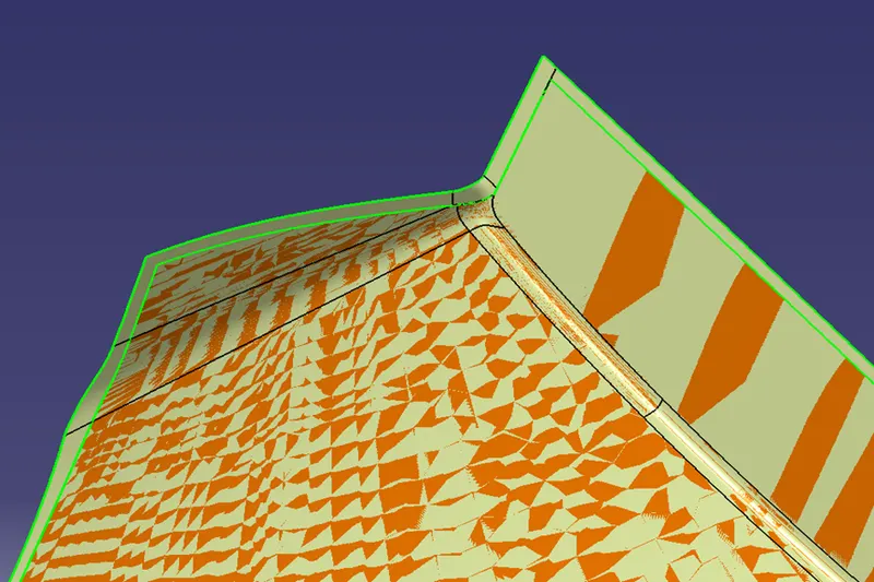
Similarly , class B surface was created for other components .
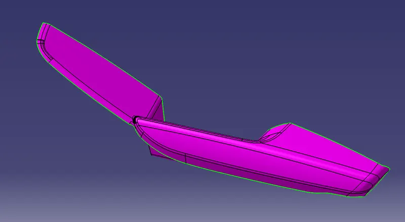
*Class B surface of ARM REST-
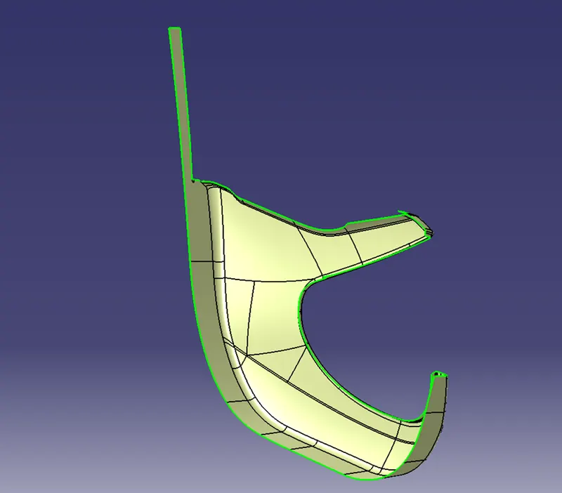
*Class B surface of LOWER SUBSTRATE-
*Class B surface of BOTTLE HOLDER-
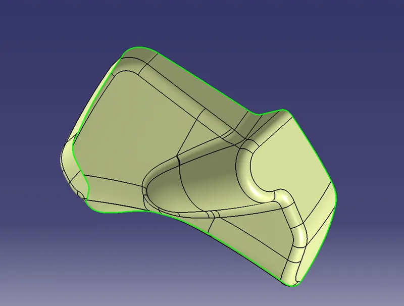
Hence class B surface for all components were created.
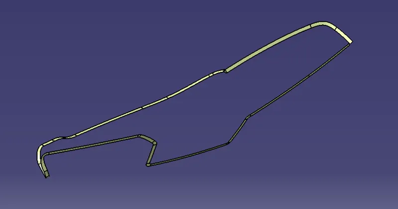
3) Creation of Class C surface-
Procedure for creation of class C surface for Upper map pocket
Step 1- Create a new surface at an angle to an existing surface using the sweep command. For free edges, this angle depends on the draught angle, and for mating surfaces, it is typically 90 degrees.
Step 2- Use Multi section surface to construct a new surface in locations where sweep is not feasible.
Step3-Join all surfaces in step 3 to create the C surface.
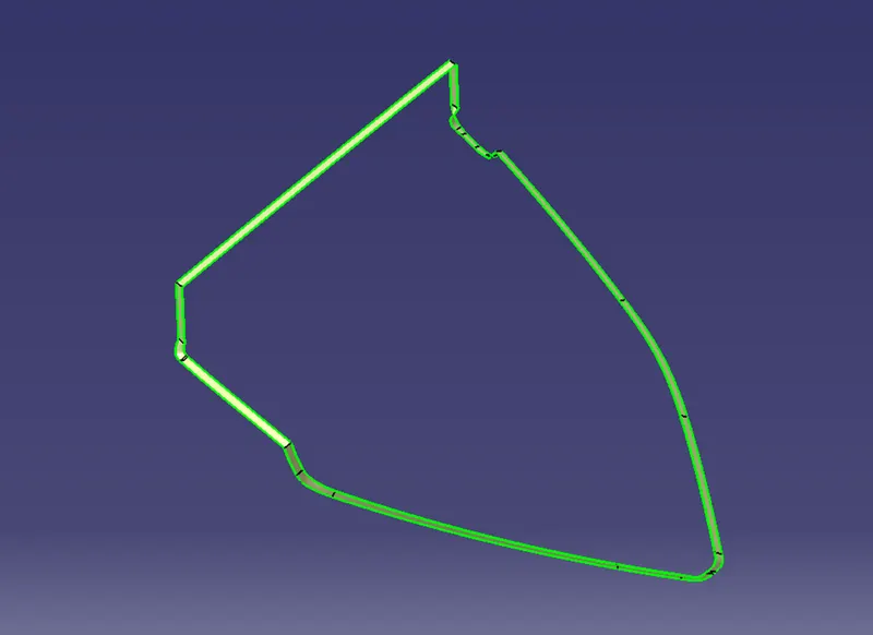
Hence C surface was obtained for MAP POCKET
Similarly, C surfaces were obtained for all other components.
Class C surface for ARM REST-
*Class C surface for LOWER SUBSTRATE-
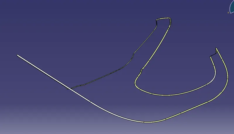
Hence class C was created for all components.
4)Creation of closed body-
Procedure for creation of closed body for lower map pocket.
Step 1- Use trim or join option to join Class A and Class C.
Step 2-Use trim option to join above trim with class B
Hence, we have obtained closed body for BOTTLE HOLDER.
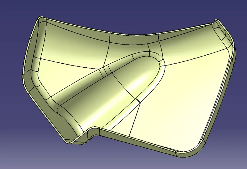
Similarly closed body was obtained for all other parts
Closed body for MAP POCKET-
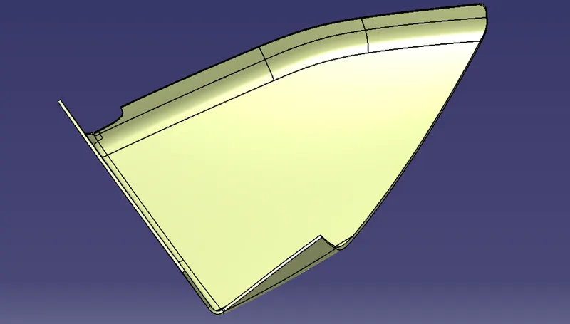
Closed body for LOWER SUBSTRATE-
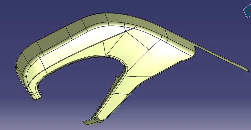
Closed body for ARM REST-
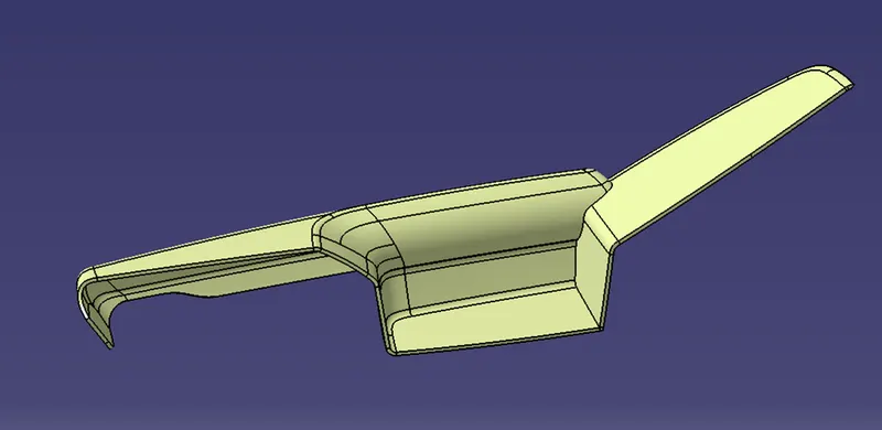
Hence, we have created closed body for all parts and thus we have created solid bodies from them.
5) Draft Analysis:
Procedure to check Draft analysis for Lower substrate.
1) Use the Publication from tool option to publish the tooling axis and the component when they have been developed.
2) Select the Feature Draught Analysis tool from the Inserts tool bar.
3) Select the Material option under Shading and modify the view option to suit your preferences.
4) After aligning it with the tooling axis, select the axis choice from the Draught analysis tools, and then select the lock option to lock it.
5) Change the value of the draught angle to 3. Select Quick Analysis Mode to display the feature using the provided colour scheme. Verify the draught analysis is clear from all angles. To end the Draught analysis mode, click ok.
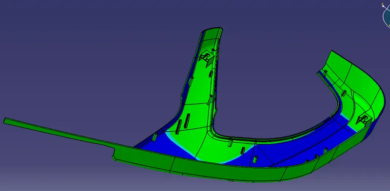
Draft analysis for MAP POCKET-
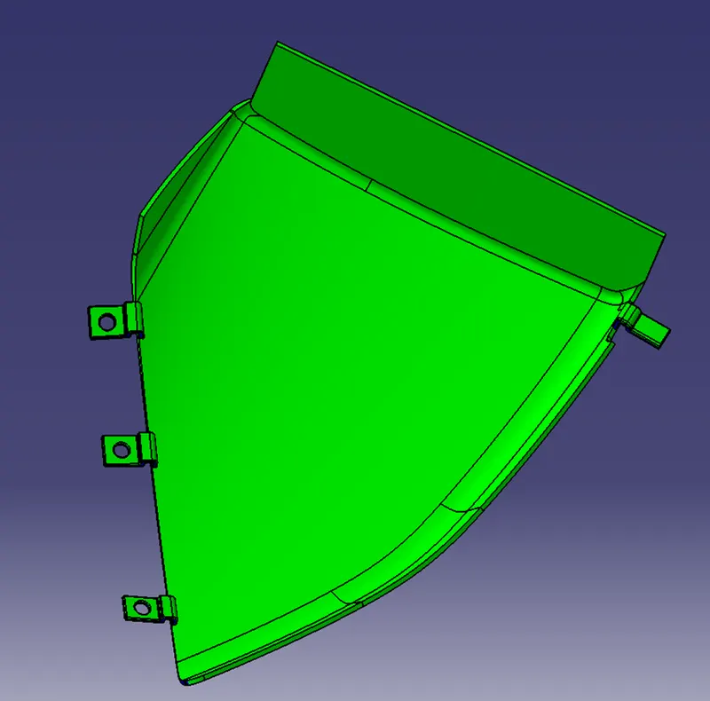
Draft Analysis for ARM REST
Hence, we have completed first part of the project and have obtained closed body for all the parts clearing draft analysis
*PART 2-
Attachment of flanges using given master sections.
Procedure to create FLANGES and HEAR STAKES for Arm rest from given master sections.
Step 1- Using several extracts, create the necessary sweep and guide profiles for the flange top surface.
Step 2- Create a surface from the numerous extracts below using the sweep option.
Step 3- Create a solid body in a new body by using extrapolate to extend the surface in accordance with the master section. Make flat surfaces with holes for the heat stake.
Step 4- A heat stake was made by padding a sketch that was made using a master section point.
Step 5- Thickening and cushioning the multiple extract from the master section were used to produce the stake support.
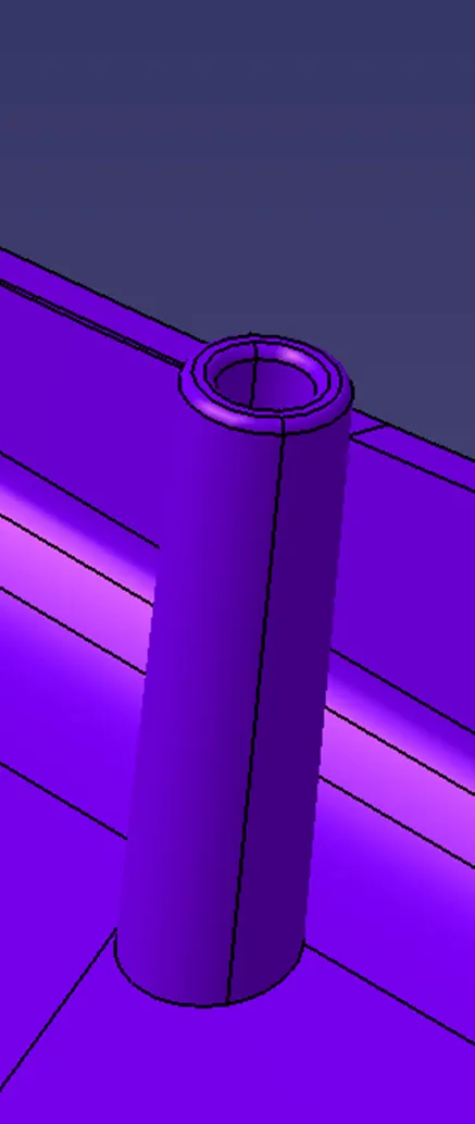
Similarly, features were created on all parts according to master section.
Flanges on MAP POCKET-
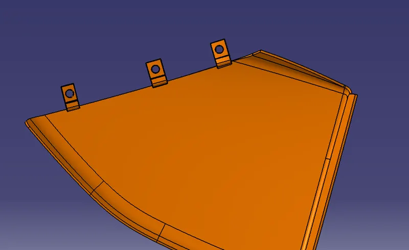
Hence, we have made features according to master section.
3) Creation dog house and additional attachment features according to industry standards.
Procedure to create dog house on LOWER SUBSTRATE-
Step 1-Create a point at the needed location and a plane from it in step one. Make a sketch using the dog house as the basis.
Step 2- Create a surface using the sweep tool using this profile and the draught direction at a 1.5 degree draught angle.
Step 3- Extrapolate and extrude options are used to construct the necessary surfaces, and trim and split options are used to obtain the dog house's outer body.
Step 4-Create a new body and give it the name "dog house" To construct a solid with the desired thickness, use the thick surface option.
Step 5- Use the translate option to translate the dog house to the desired height, and the thick command to expand the base surface so that it intersects the bottom substrate.
Step 6-To obtain the necessary base profile, extract the inner base edge and build a surface. Create a solid using a thick surface, and then use a Boolean operation to remove it from the dog house's base.
Step 7-produce a sketch, extrude it, then divide it from the solid using the split option to produce the top profile for attaching push pins.
Step 8- Create another drawing, extrude it, then off-set it to create a base for push pins to rest on. Use the thick surface option to convert it into solids.
Use Boolean operation union trim to obtain required design.
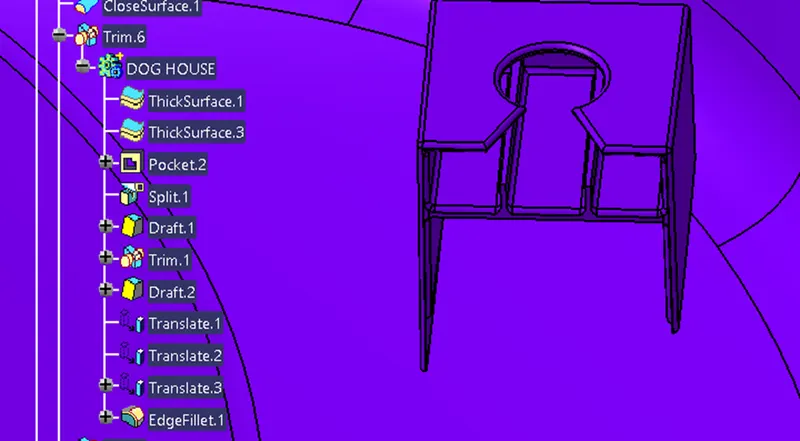
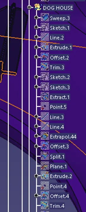
Thus, we have created dog house.
Now we have made complete dog house. Use translate (point to point) option to position it in required locations.
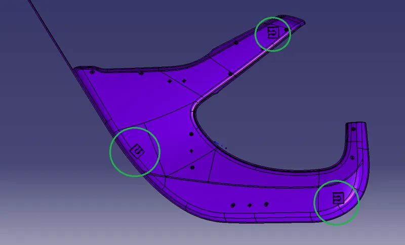
Create heat stakes and flanges at required locations using above mentioned procedures to obtain complete substrate body. Apply draft on all required surfaces and fillets on all straight edges.
Final MAP POCKET-
Final ARM REST-
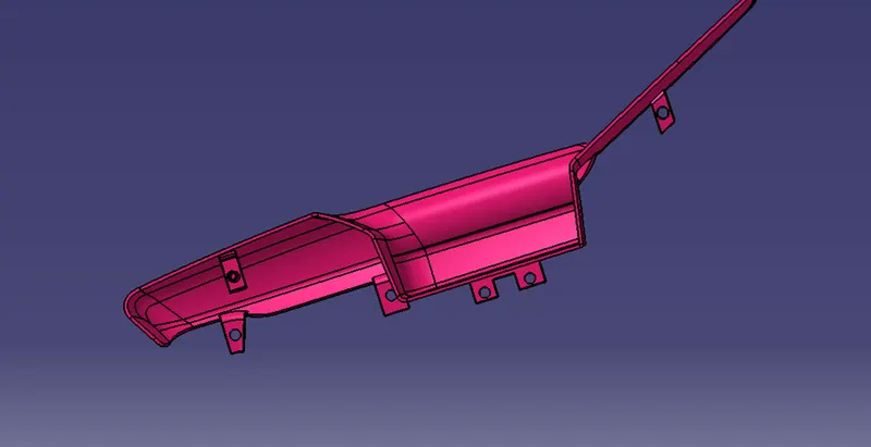
Final BOTTLE HOLDER-
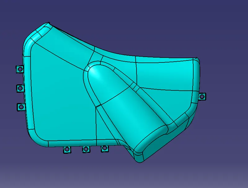
Draft analysis for Completed parts
1)ARM REST-
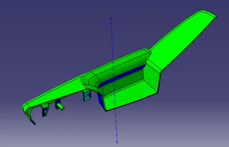
2) Lower Substrate-
3) MAP POCKET-
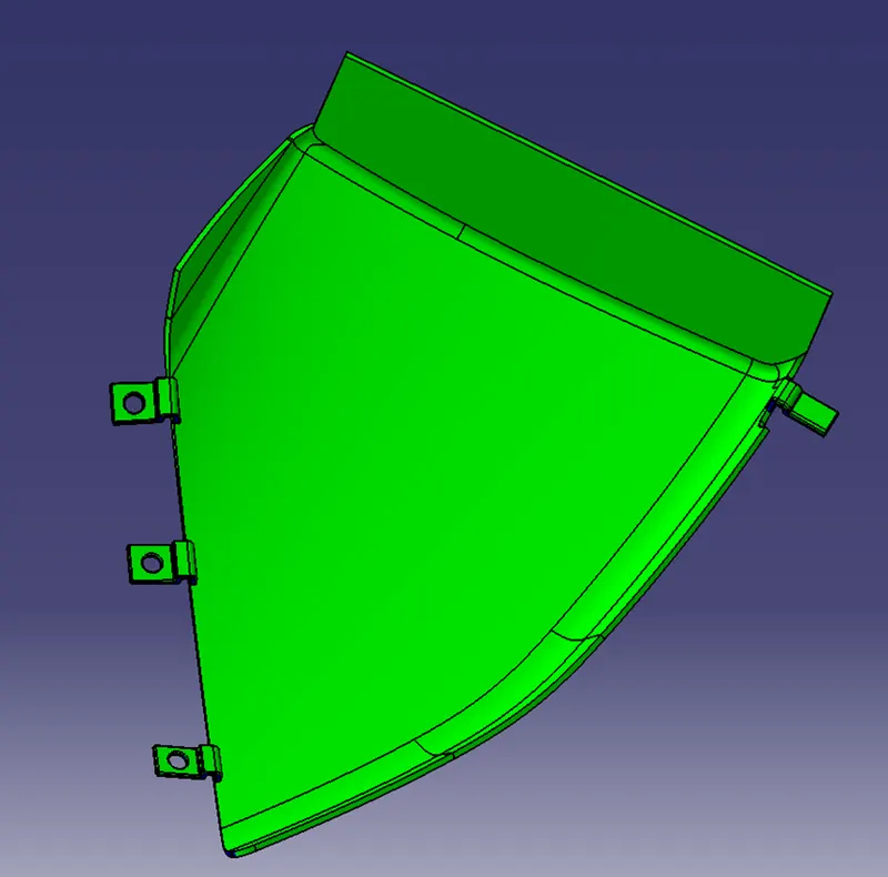
4)BOTTLE HOLDER-
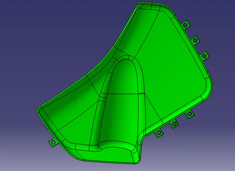
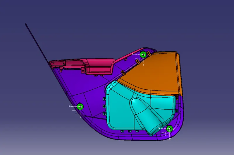
COMPLETED DOOR TRIM-
*CONCLUSION-
In order to produce the CAD model, the following inputs are taken into account, same like in OEM and tier1 firms.