Week 12- Final project
|
Development of a Door Trim panel |
Aim:
Creation of CAD model considering CLass A surface, nominal thickness, and attachment features.
Abstract:
The project report explains steps and procedures followed while developing the Door Trim Panel of a car using CATIA V5. Using the CLASS-A surface and master sections as input, we were able to create a Tooling axis, CLASS-B surface, CLASS-C surface, Flanges and form a solid body after which the attachment features such as Dog House, Push Pins, Heat stakes, etc are created. To check the manufacturability of the parts, a Draft Analysis has also been performed using the main/side tooling axis on various components such as lower substrate, map pockets, armrest, etc.
Objective:
Creation of CAD model considering following inputs as like in OEM and tier1 companies
- Class A surface
- Nominal thickness: Refer to master sections
- Attachment strategy: Flanges, Heat stakes, and Dog house.
Detailed report:
Method followed:
- Class A modification of given Class A.
- Creating A Class B and C surface.
- Create Thickened part using the master section for reference.
- Create the mounting features as per design guidelines in the industry and with master sections.
- Performing a draft analysis.
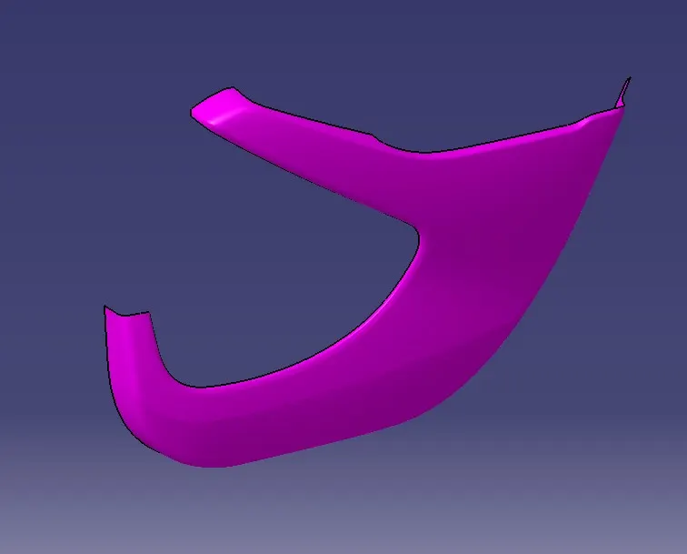
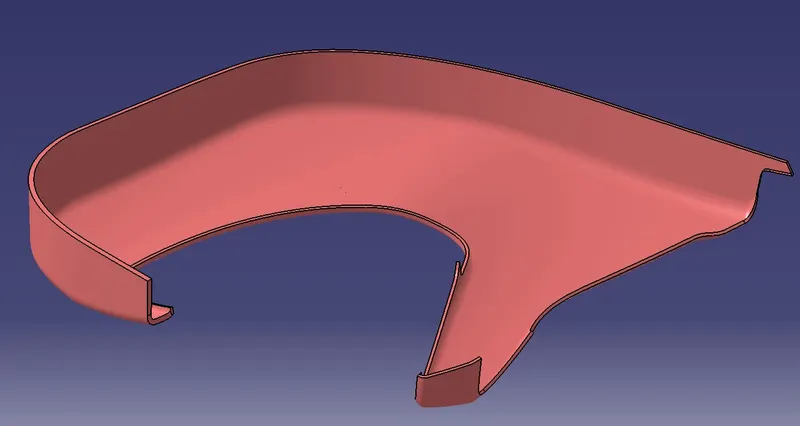
- Lower substrate:
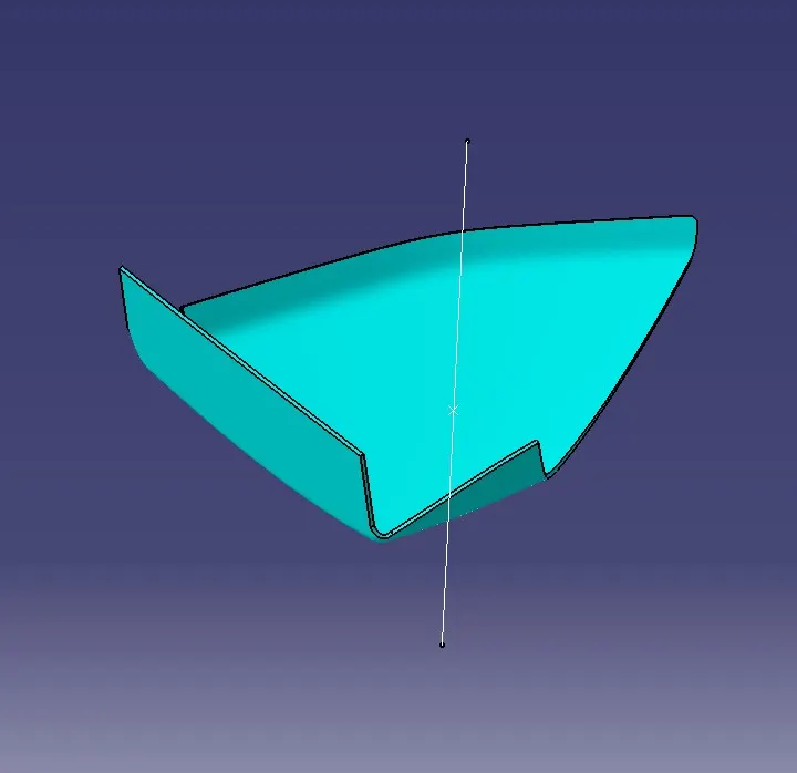
Map pocket:
- Inner map pocket:
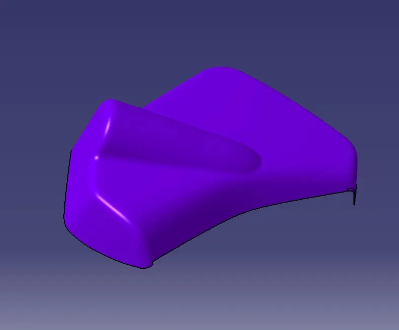
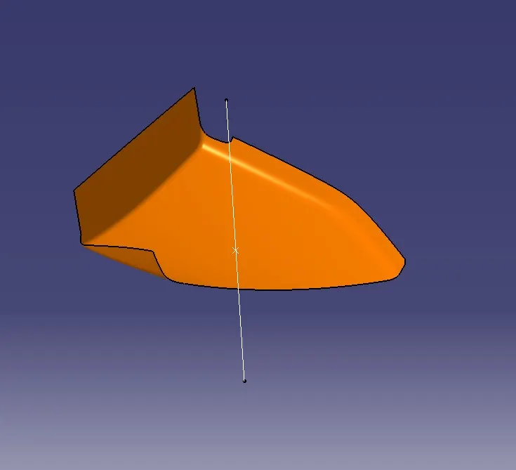
- Outer map pocket:
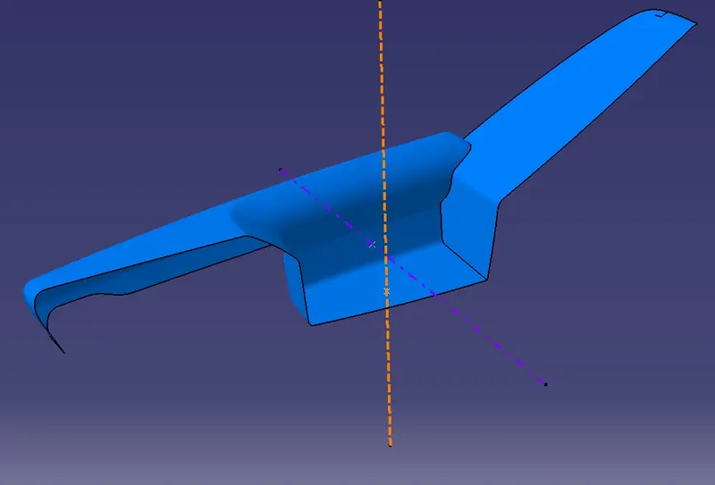
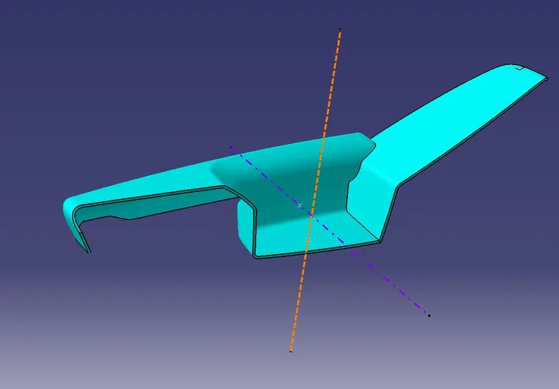
Door armrest:
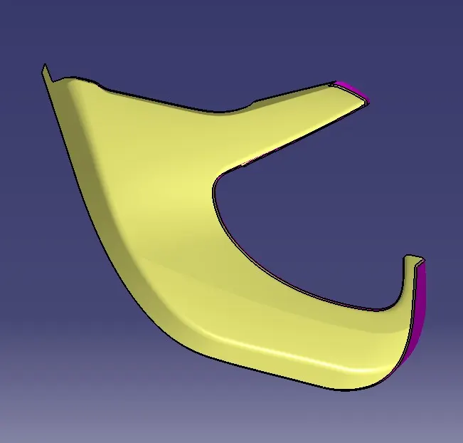
1. Lower substrate:
To get a Class B,
First of all, we offset the Class A on 2.5mm in the required direction. For intersecting Class B with Class C, we need to extrapolate the offset of Class B.
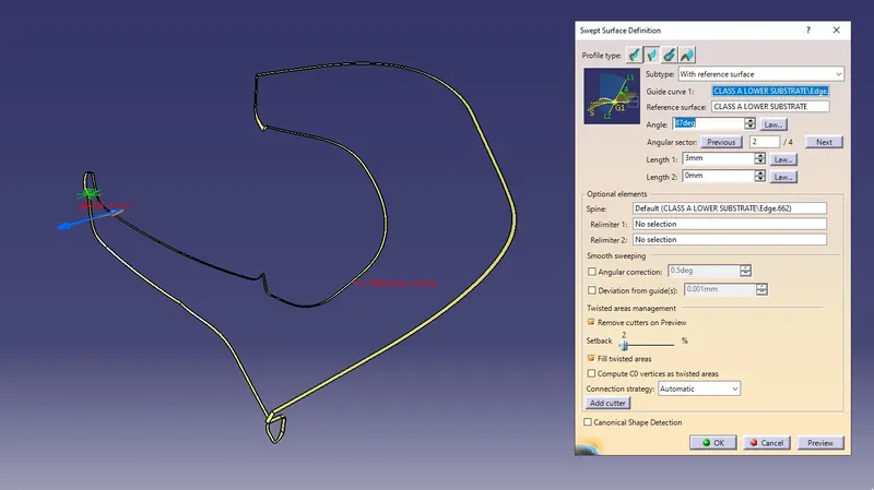
Next, we need to make a Class C from Class A so we just use a sweeping command with a reference surface of 87 degrees draft angle with the required direction.
2. Map pocket:
Here we divide the Outer map pocket and Inner map pocket by extracting them separately.
- Outer map pocket:
First, we offset the extracted Class A for 2.5mm distance which is the minimal thickness of the component.
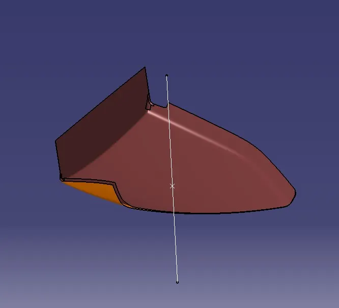
Next, we extrapolate by adding edges in the command of Class B to intersect with the C surface.
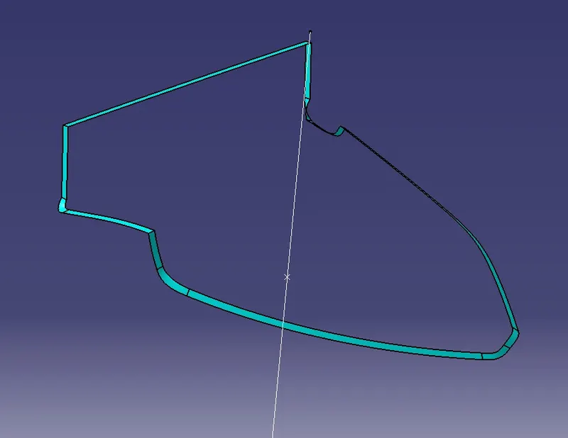
Then give Multi-Section Surfaces where extrapolate is not working especially in curved sections.
After that, we used to sweep concerning the Class A surface at 87 degrees by visualizing which direction we needed to sweep the surface.
- Inner map pocket: we did the same operations which are followed for the outer map pocket.
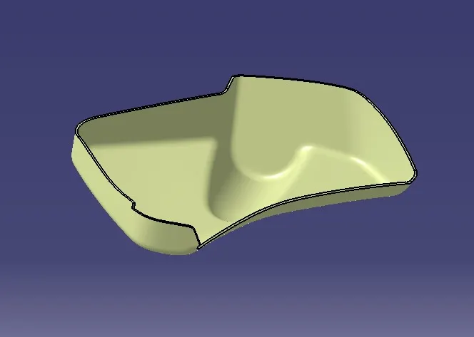
3. Door armrest:
In, Door armrest we divided it into parts by extracting it separately and worked on it to neglect the error on the Class B surface.
We have done the same operations on door armrests which apply on map pockets and the lower substrate.
Class A and B surface:
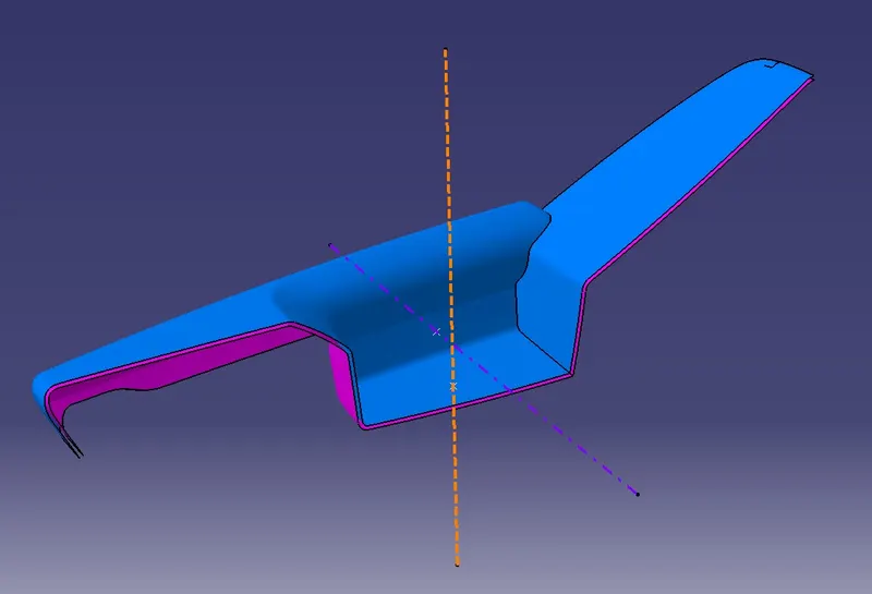
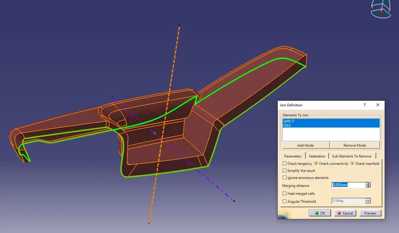
Joining Class A and c surface:
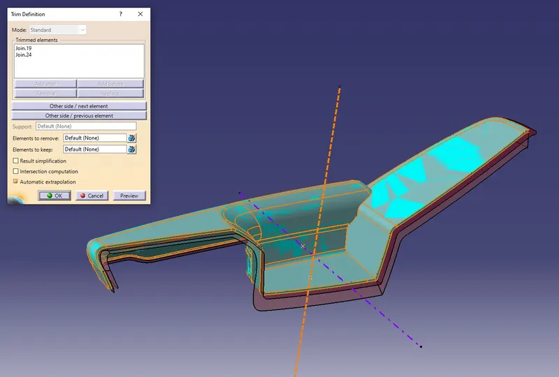
Trimming it with extrapolated Class B
- Create a solid body using the master section for reference:
First, we go to the part workbench, next create a new body then use a close surface feature and finally we get our final output of a nominal thickness of 2.5mm measured from master sections.
Lower substrate
BOTTLE HOLDER
Outer map pocket
Door armrest
- Creating the mounting features as per design guidelines in the industry and with master sections:
- Flanges:
First, we extract the curve that lies on the body
Next, we make a point on it and use a point repetition operation with the distance between 60-100 according to the design rule for flanges
Then add the plane and sketch the flange and constraint it.
- Heat stakes:
First of all, we made a point on the surface in the middle of both sides.
Next, I need to make a plane by offset from the plane then make two circles of D10 & D9.4. Bigger circle for making a hole on a flange and another one is for heat stake.
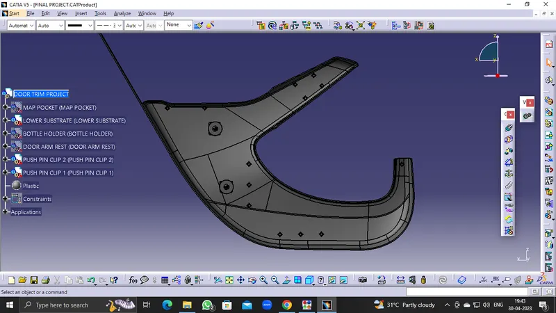
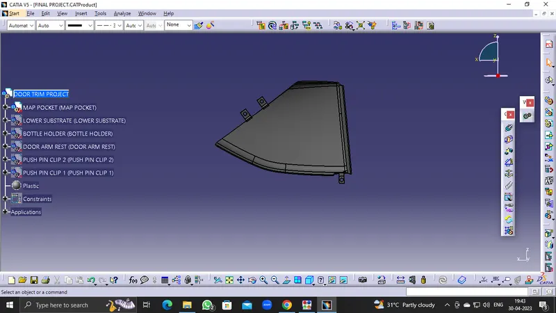
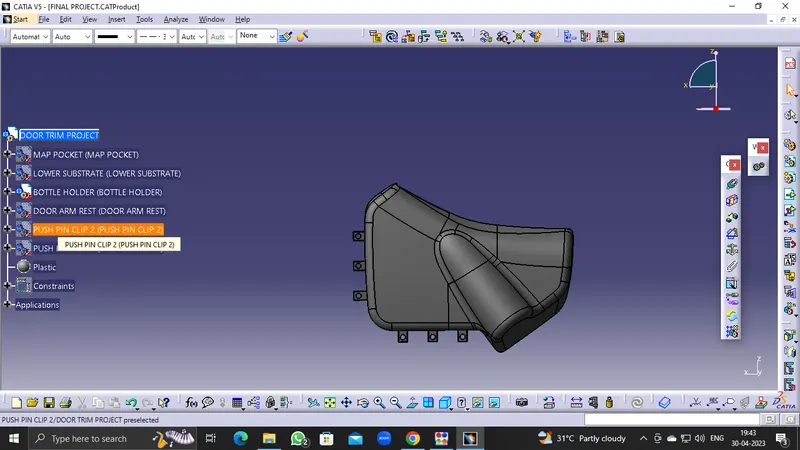
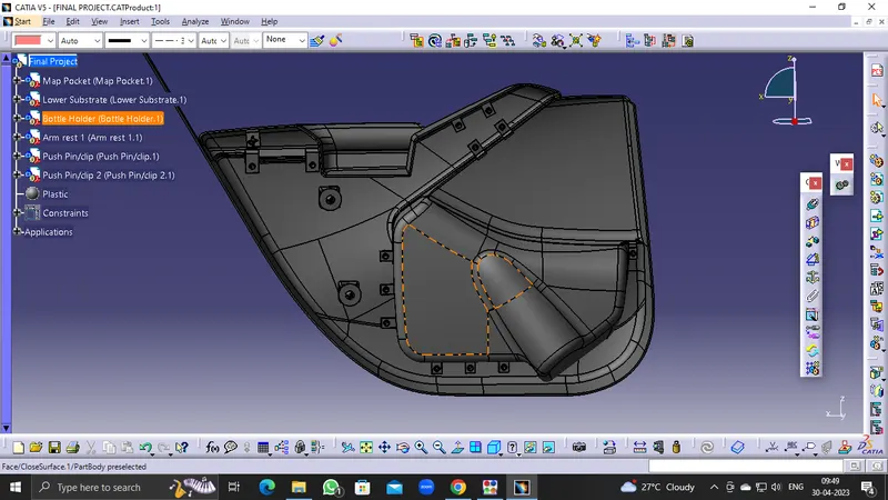
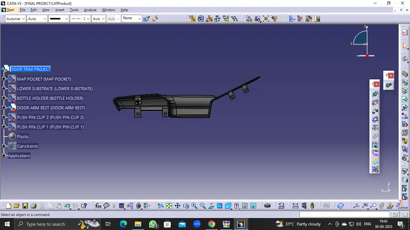
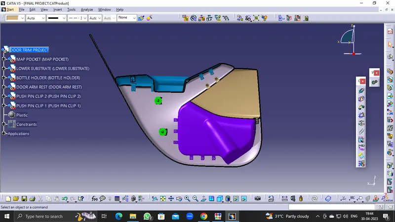
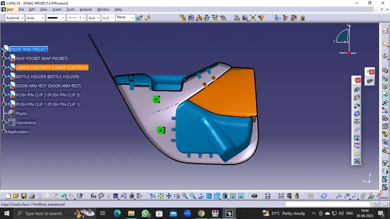
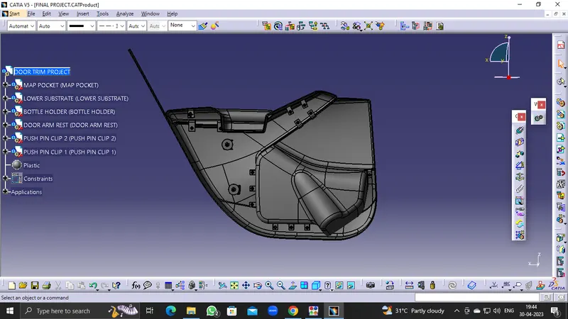
Result & Conclusion:
A Door Trim Panel with engineering features using the master section and styling surface as an input has been successfully created and draft analysis has also been performed for the same.