Week 12- Final project
Development of a Door Trim panel,
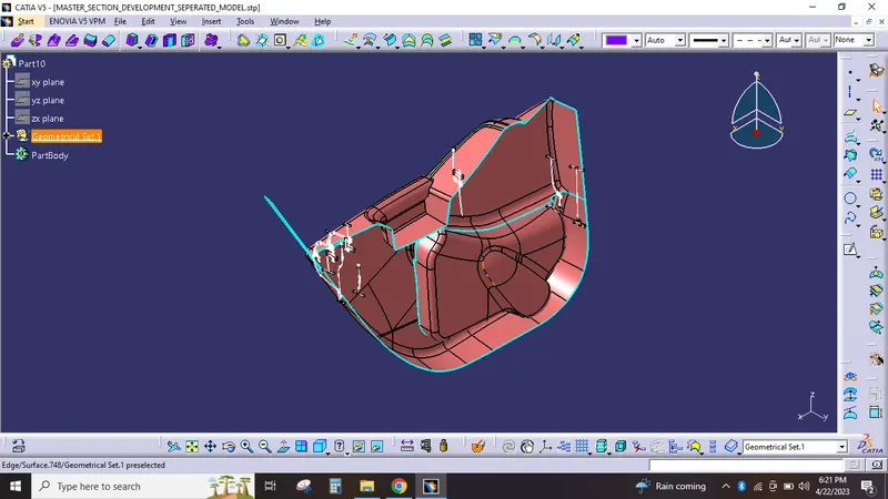
Given Class A surfaces with master sections,
Final completed product file model,
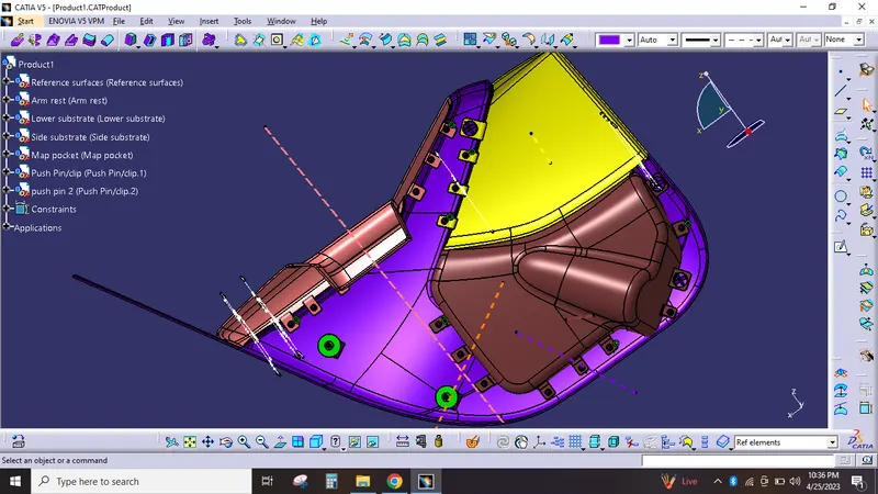
BELOW ARE THE STEPS FOLLOWED IN DEVELOPMENT OF DOOR TRIM PANEL:
Creation of Solid surfaces,
From the given class A surface using main tooling axis and direct offset method the below closed surfces have made with the help of master section ( thickness 2.5mm ).
Arm rest solid body,
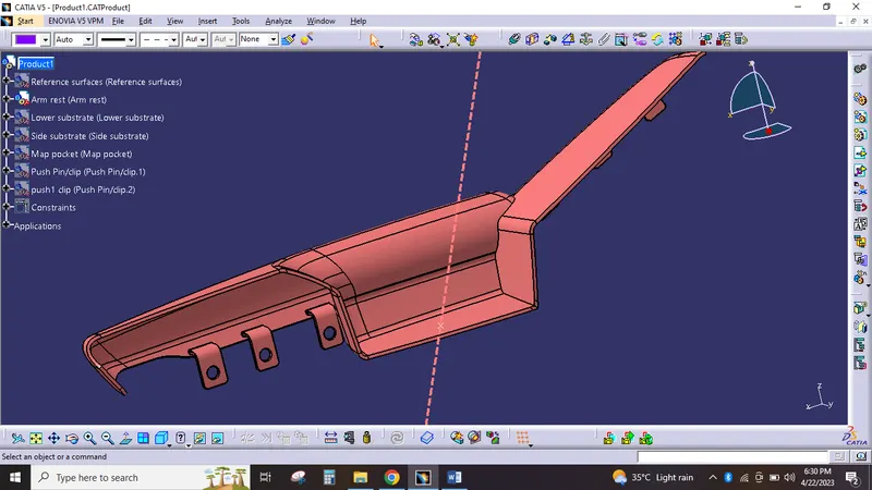
Lower Substrate solid body,
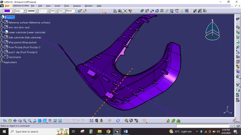
Side substrate solid body,
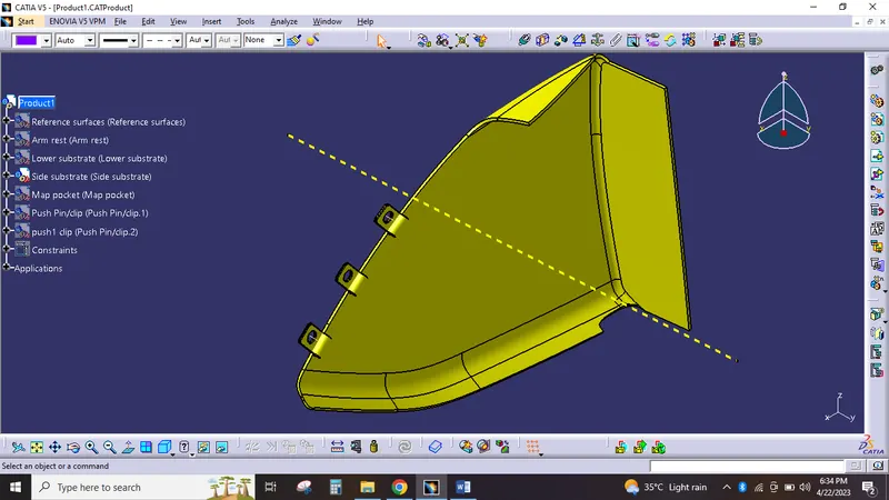
Map pocket solid body,
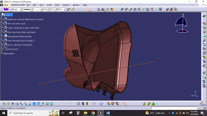
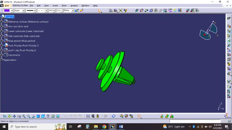
Input solid body push pin,
Draft analysis,
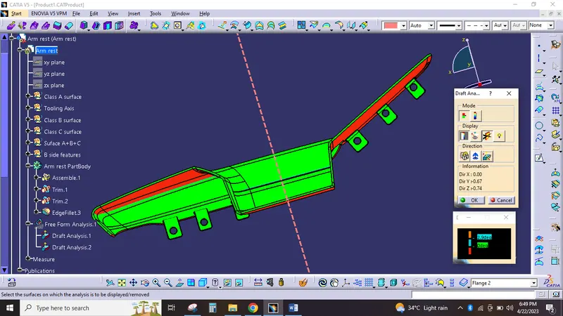
Here i have done two draft analysis for each part 1st one is for class A surface and the 2nd is for the solid body.
Draft,
Draft is an angle provided to the plastic part, which is used to eject or removes the material from the mold easily without any damages. Draft is a taper applied to the faces of the part that prevent them from being parallel to the motion of the mold opening.
Draft analysis,
Draft analysis, which is used to find out the proper tooling axis of a plastic component. it is a technique used to analyze whether our part model created in CAD is manufacturable based on the draft condition applied.
Creation of tooling axis,
Steps for draft analysis using bisecting method,
- Refer the views of the given class A surface in X,Y,Z directions. finding out the direction where most of the surface are visible.
- In this most of the surfaces visible only in Y direction.
- In Y direction dummy tooling axis has drawn in a flat surface.
- An axis system fixed in the reference point in which dummy axis has drawn.
- Then using the yz plane and class A surface to get the intersection line.
- Based on the intersection lines which are parallel to the dummy axis are selected for to get the proper tooling axis.
- The parallel lines are extrapolated or a new line is has drawn on the same intersected parallel lines.
- Based on the extrapolated parallel line one line has drawn by using the bisecting line command.
- In this class A surface tooling clearing in Y direction is considered as Tooling axis.
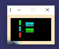
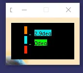
- In the main tooling axis the draft analysis compass has fixed and used the running point i have measure some points. at the end i have found out the draft angle as 2.9 deg for closure cad part.
- I have given 0.5 deg of draft for the b side features.
- And i have changed the green side in top using the flip option, have changed the colors in color scale.
- At the end of class A surface draft analysis i have got complete green surface ( cavity side ).
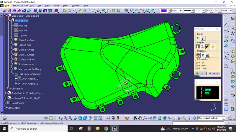
- At the end of solid part draft analysis i have got cavity side as green in color, core side as red in color.
(The above steps are used to make the main tooling axis for all given surfaces)
Arm rest class A surface draft analysis,
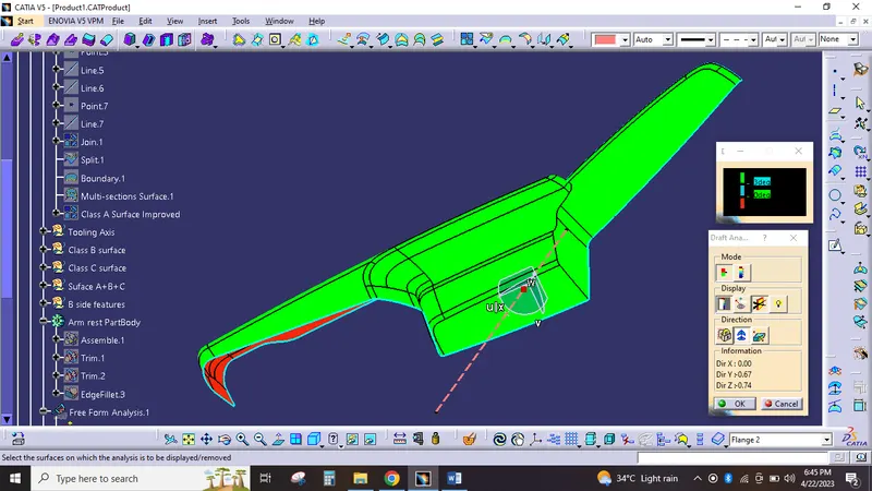
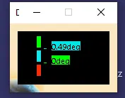
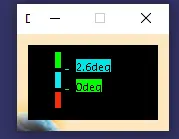
Color code scale,
Arm rest solid body draft analysis,
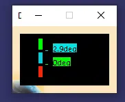
Lower substrate class A surface draft analysis,
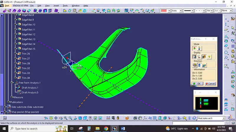
Lower substrate solid body draft analysis with B side features,
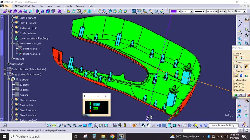
Dog house draft analysis with side core axis,
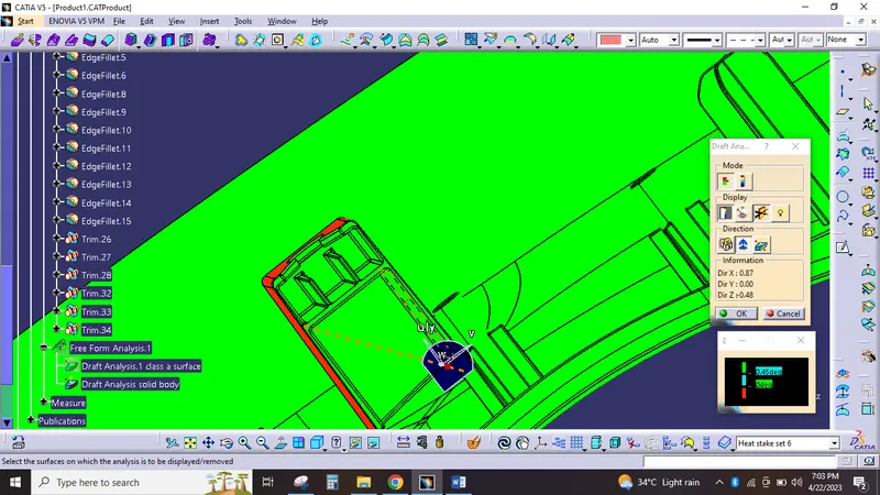
Locators and heat stakes,
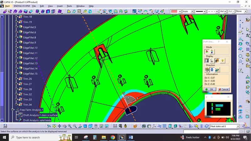
At 0.49 degrees B side features clearing the draft analysis with side core axis,
Side susbstrate class A surface draft analysis,
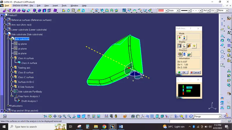
Class A suface clears at 2.9 deg,
Side susbstrate solid body draft analysis,
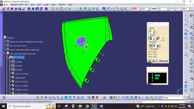
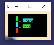
Most of the C surfaces clears at 2.7 degrees,
Map pocket class A surface draft analysis,
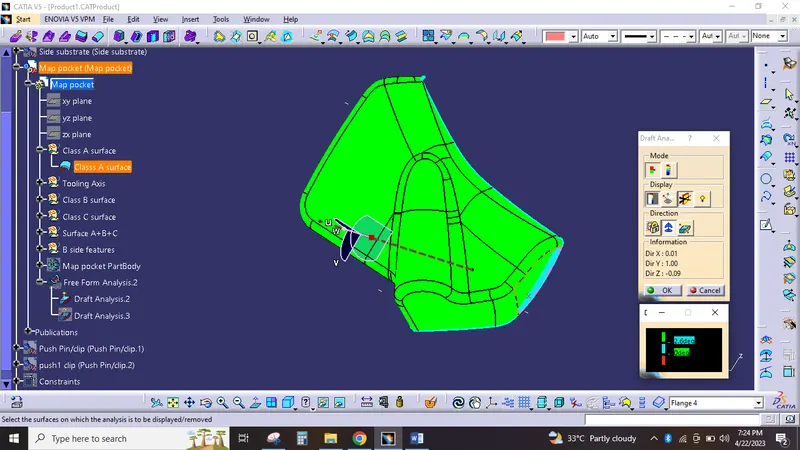
Class A surface mostly clears at 2.6 deg.,
Map pocket solid body draft analysis,
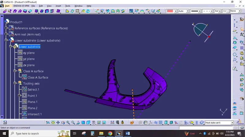
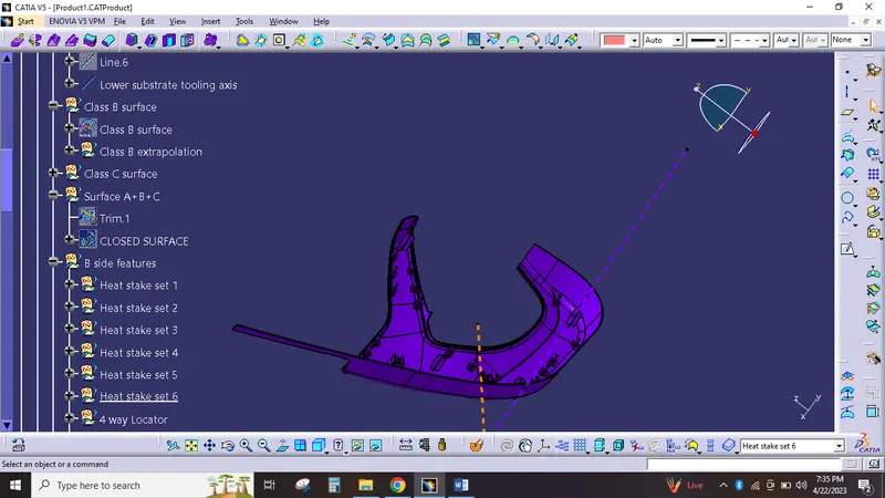
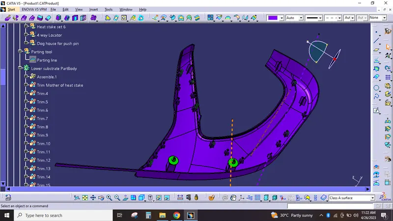
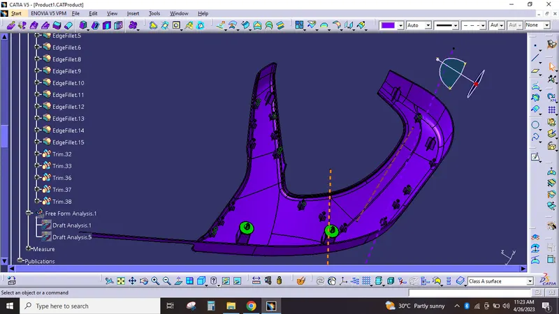
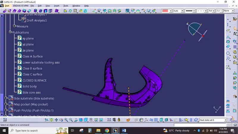
Model Tree Structure,
Here i have attached the tree structure for lower susbstrate solid body, the same structure has followed in other surfaces.
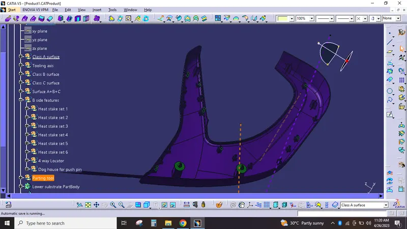
Tree expansion,
Publications,
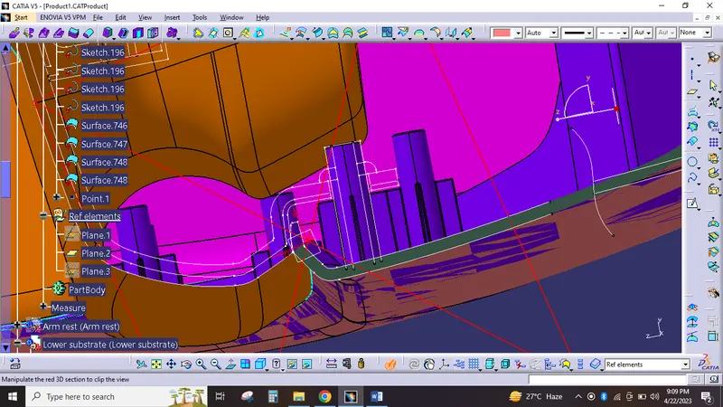
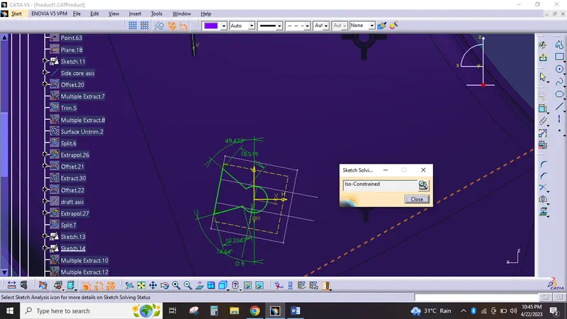
Sketches and Procedures followed in the creations of B side features,
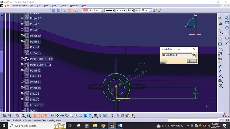
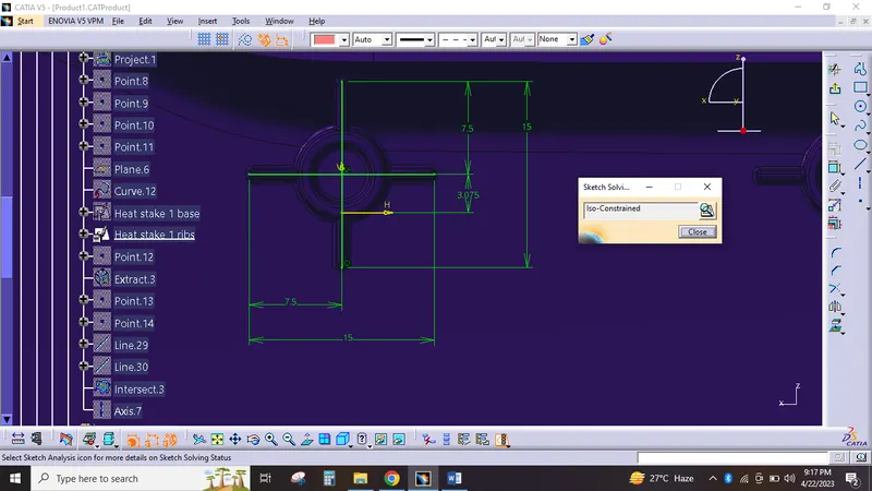
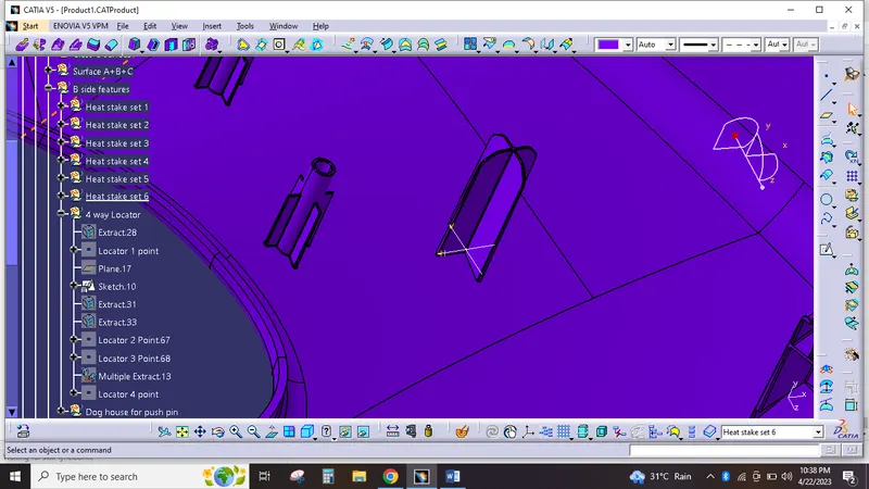
Heat stakes with rib support,
As per master section,
Heat stake inner diameter = 4.5 mm
Outer diameter = 7.5 mm
Height from base = 26 mm
Heat stake ribs thickness = 1 mm
Height of the ribs = Upto flange bottom surface.
Flange creation,
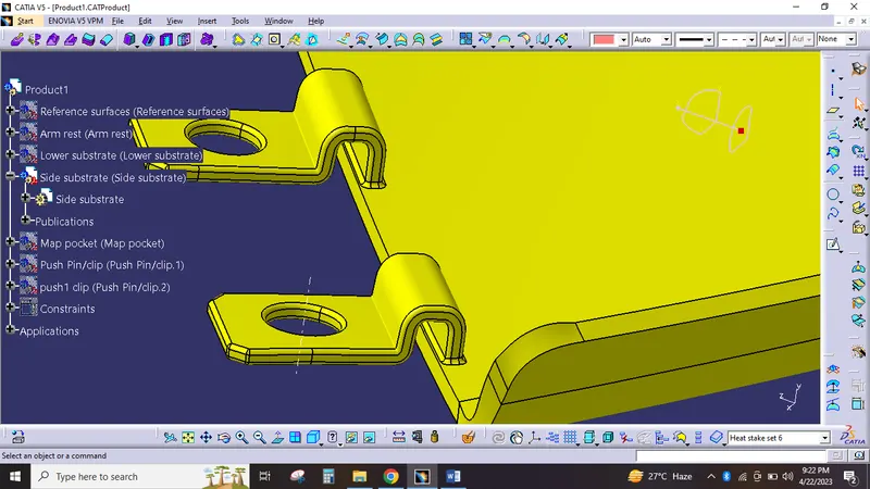
Master section multiple extract,
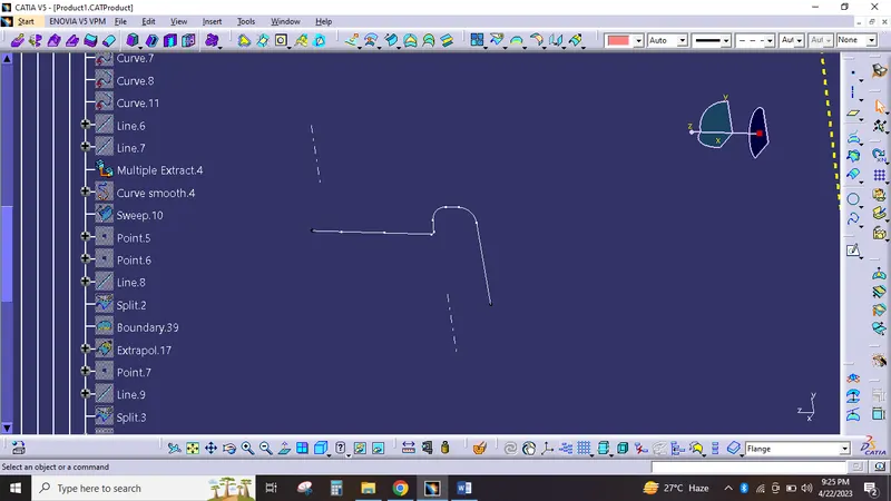
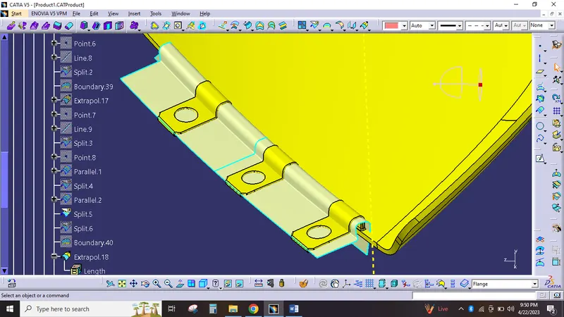
Using the sweep option profile as master section and the base C surface bondary as guide curve. i have thicken the sweep upto 2mm thickness then i have seperated the flanges as per requirement using the solid N surface split command.
Flange holes with heat stake allowance 0.5 mm around the heat stake, can be made by the commands of extract,offset and solid surface split, 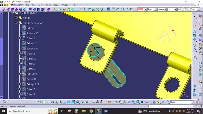
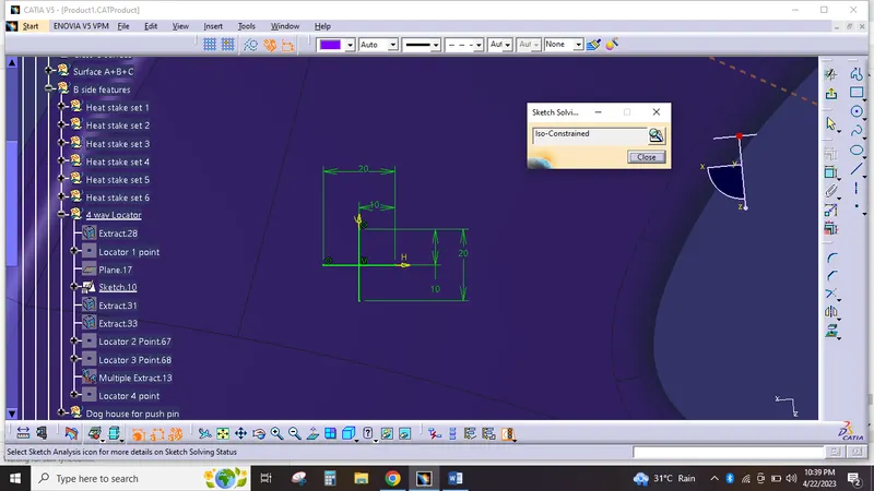
4 way Locator,
Thickness of locator = 1.5 mm
Length of locator = 20 mm
Width of locator = 20 mm
Height of locator = 41 mm
Dog house with push pin holder,
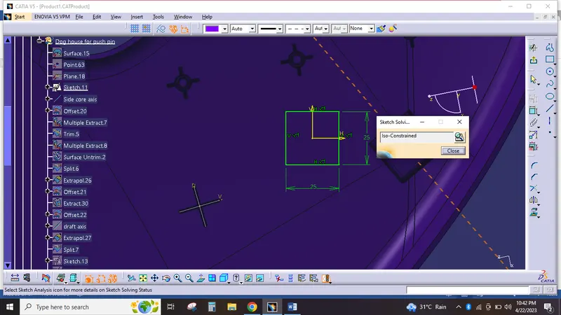
Dog house width 25 mm, height is 50 mm other dimensions are refered from the A pillar dog house drawing and as per design rules.
Ribs,
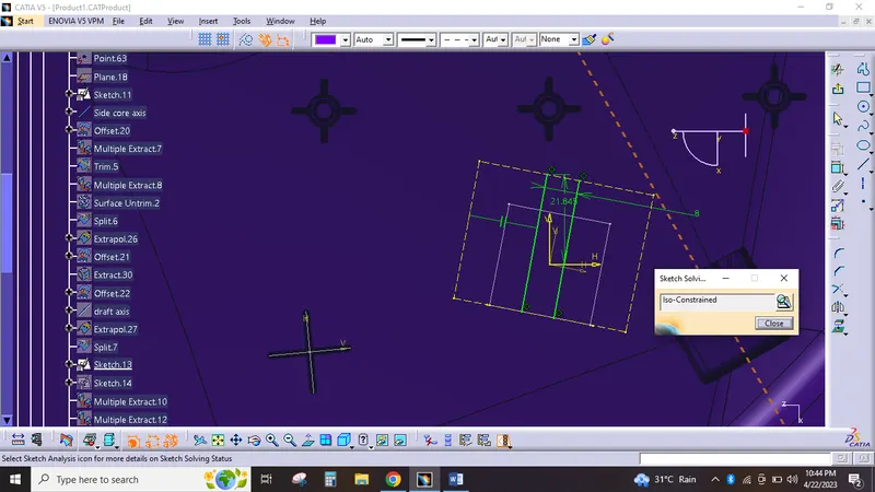
Push pin holder,
final developed model,
Used the constraints option in product workbench i have fixed the push pin in the dog house properly.
Conclusion:
Thus the door trim panel surfaces developed as per the design rules and requirements. and i have enclosed the assembly product file and each seperate part files for the references.