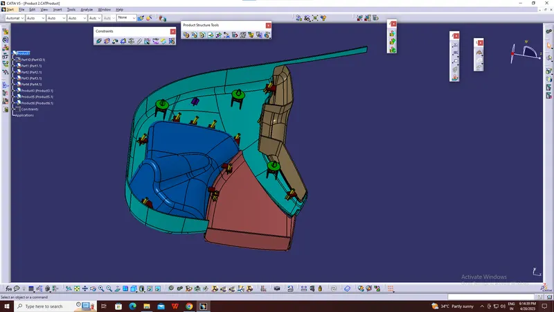
Week 12- Final project
Project Title : DEVELOPMENT OF A DOOR TRIM PANEL
OBJECTIVE :
The Objective of the project is to development of vehicle interior door trim panel by using CATIA V5 With given class-A surface along with the master seection. Also Create the side attachment feature as per design rules.
INTRODUCTION :
The door panel is the interface between the interior of the car and inner working of the door. Generally, the door panel is divided into parts for easy designing like arm rest, map pocket, Lower substrate. These require one of the toughest requirements amoung the interior parts of the car. This should be designed to with stand the load while being less than 2mm thickness and also to protect the occupants during collisions.
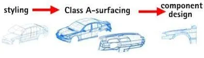
Class-A Surfaces :-
In automotive design a Class-A surface in any of a set of from surface of high efficiency and quality. Although strictly its nothing more than saying have curvature alignement to ideal aesthetical reflection quality, many people interpret class-A surface to have G2 or even G3 curvature continuity to one another. Class-A surface is creating by using computer Aided digital applications. Class-A surface modellers are also called digital sculptors in the industry.
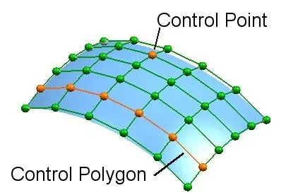
Class-B Surface :-
Class B surface are Engineering Surfaces which are invisible to the eyes or often on the back side of the Class A surface. It is mainly the thickness of the component or Class A. These surfaces need to be designed as per the Class A surface i.e., the continuity, thickness of the component, functionality etc should be maintained. These surfaces include the main engineering features such as Screw bosses, Ribs, Snaps, Stiffeners and fixations. B surfaces also do not contain any aesthetic styling content and textures since it is not visible to eyes.
Class- C Surface :-
Class C surfaces are connectors between Class A and Class B surfaces. This surface connects both A and B surfaces along the tooling Axis. It contains the draft as per the design. It is basically the thickened surface between both A and B surface.
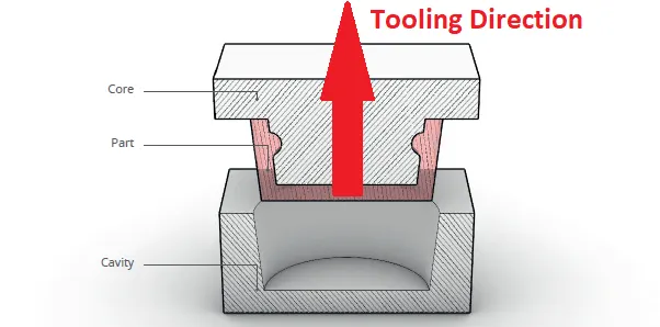
Tooling Axis:
Tooling Axis is the direction in which the Mold opens and closes. Part Drafts are generally given along this axis.
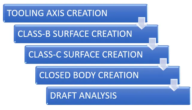
3) DESIGN METHODOLOGY OF DOOR TRIM PANEL :
4)GIVEN DATA
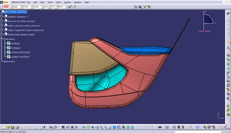
5) PROCEDURE OF DOOR TRIM PANEL :
The door panel is divided into four parts for easly to design. There are,
- Door Arm Rest.
- Lower substrate.
- Outer Map Pocket.
- Inner Map Pocket.
A)DOOR ARM RESRT:
GIVEN CLASS A SURFACE
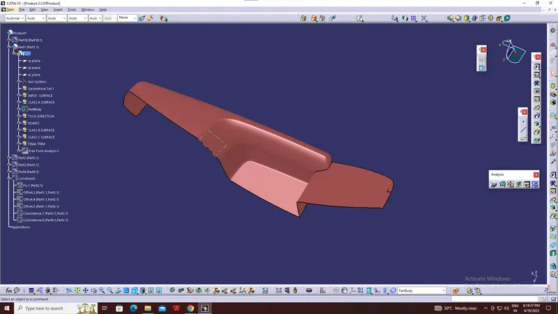
Tooling Axis :
Class-A surface is first analyzed to create the tooling axis. where the molds pull apart in injection molding. Tooling direction is essential for plastic product design as it decides the direction for mold separation.
To create the tooling axis first we have to check the best suitable direction for tooling by using the compass. the y direction is suitable for creating the tooling axis because in the y direction most of the surfaces are clearing while performing draft analysis. Generally tooling axis is created using bisecting line method but here A line normal to the surface is created in the y direction and considered the tooling axis.

CREATION OF CLASS B SURFACE:
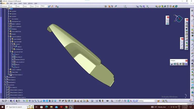
In this component Creation of the class B surface first, we have to offset the entire model by 2.5mm outward some of the surfaces give offset error and ask for offset without these subelements click okay and work on the incomplete surfaces by using the multi-section surface command, sweep and different commands used to complete the class B surface.
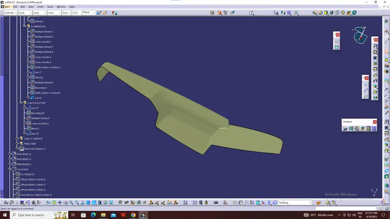
Class B OFFSET
CREATION OF CLASS C SURFACE:
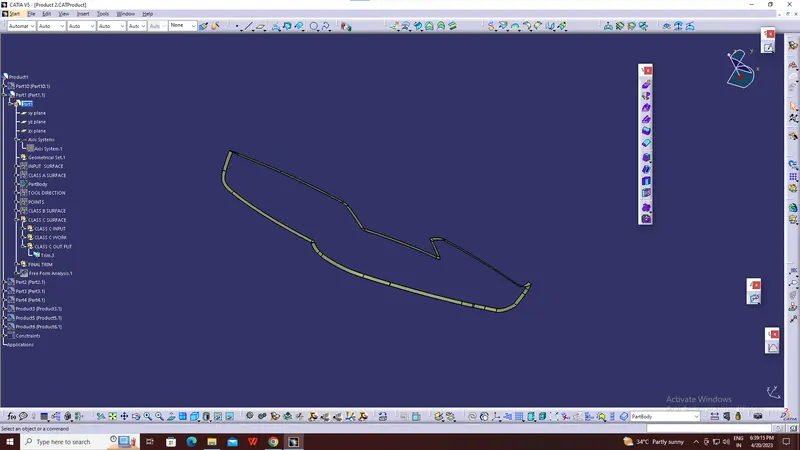
We first extract the edges from the Class A surface with the help of the multi extract or boundary command which we create the path for a sweep for class C
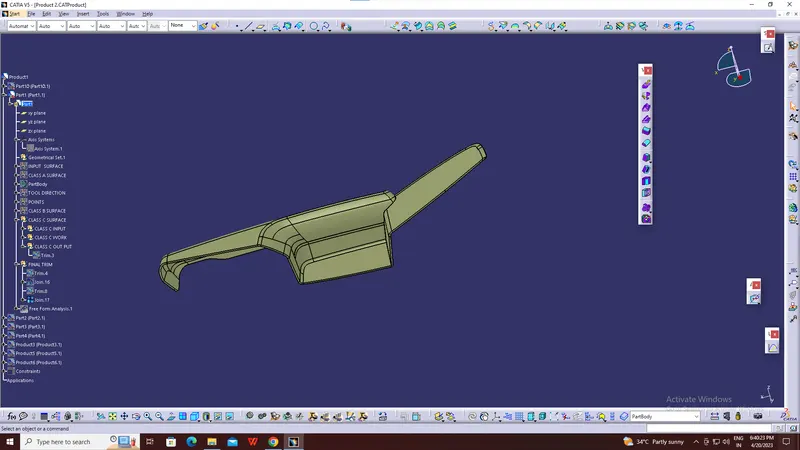
like this, we have to create all separate sweeps and join them together. once all the sweeps are joined together we created a class c surface.
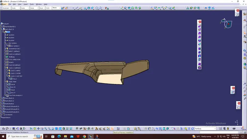
Solid component.
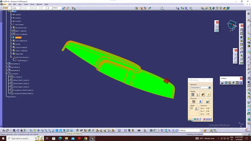
DRAFT ANALYSIS :
The Draft Analysis is a command that enables you to detect if the part you drafted will be easily removed. This type of analysis is performed based on colour ranges identifying zones on the analysed element where the deviation from the draft direction at any point, corresponds to specified values.
Draft analysis is done after determining the tooling axis, draft analysis is used to check whether the minimum draft (3 degrees) is maintained or not.
- Procedure for performing the draft analysis are as follows
- Change the view mode of the component to be in customized parameter mode and then select the shading mode as materials.
- Then open the featured draft analysis tool from the insert menu.
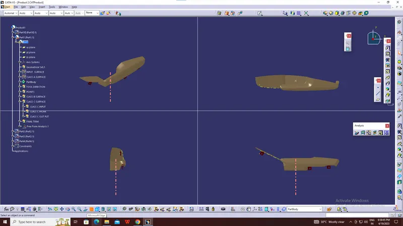
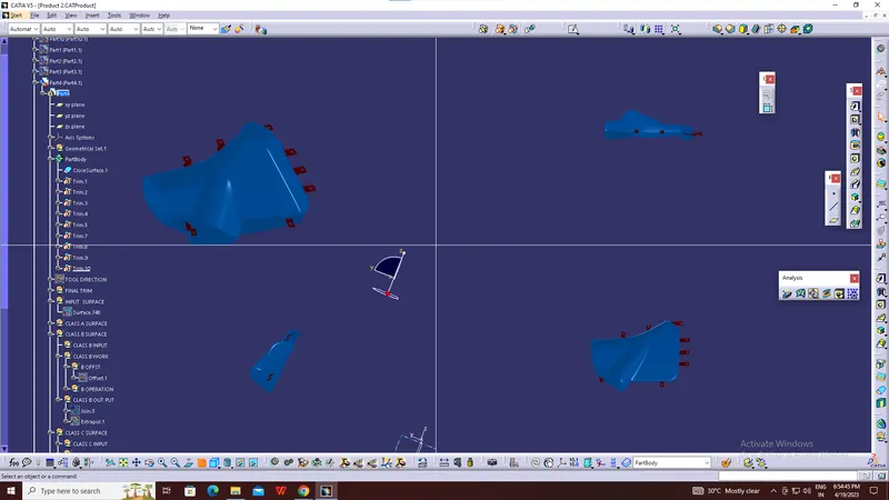
completed design in various orientations (Isometric, Front, Side, and Top View)
B)LOWER SUBSTRATE:
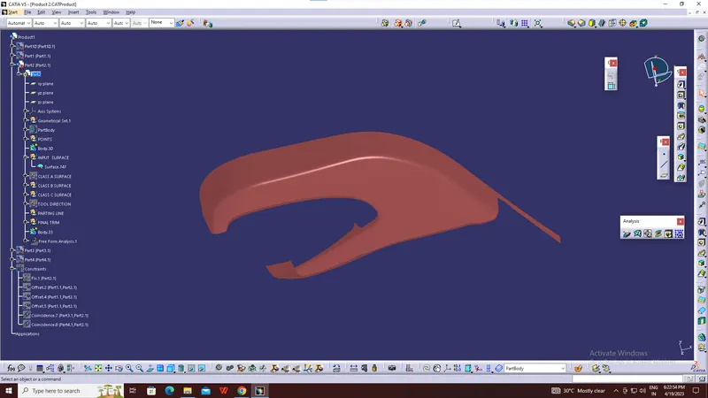
GIVEN CLASS A SURFACE
Tooling Axis :
Class-A surface is first analyzed to create the tooling axis. where the molds pull apart in injection molding. Tooling direction is essential for plastic product design as it decides the direction for mold separation.
To create the tooling axis first we have to check the best suitable direction for tooling by using the compass. the y direction is suitable for creating the tooling axis because in the y direction most of the surfaces are clearing while performing draft analysis. Generally tooling axis is created using bisecting line method but here A line normal to the surface is created in the y direction and considered the tooling axis.
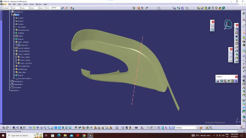
CREATION OF CLASS B SURFACE:
In this component Creation of the class B surface first, we have to offset the entire model by 2.5mm outward some of the surfaces give offset error and ask for offset without these subelements click okay and work on the incomplete surfaces by using the multi-section surface command, sweep and different commands used to complete the class B surface.
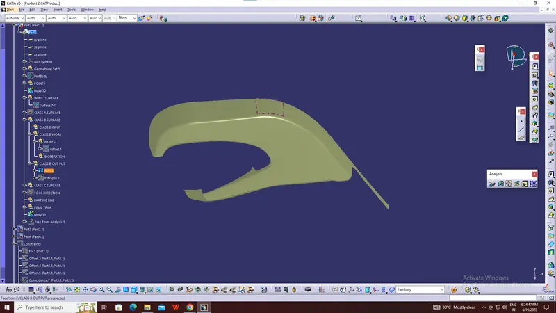
Class B OFFSET
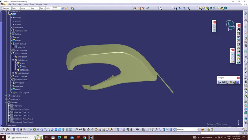
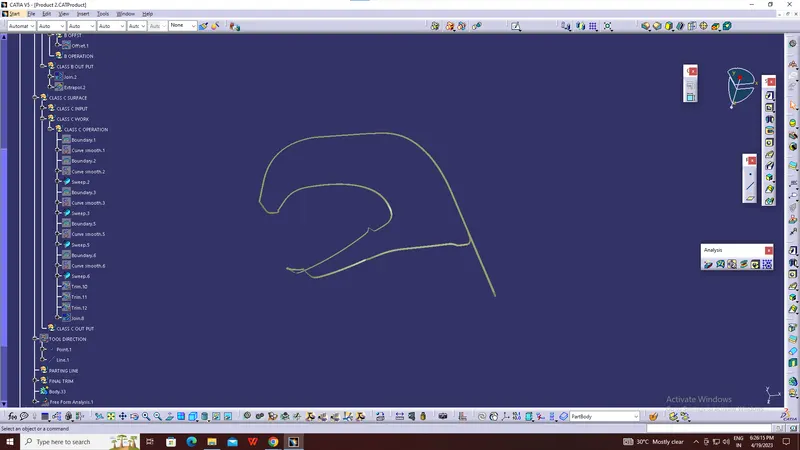
CREATION OF CLASS C SURFACE:
We first extract the edges from the Class A surface with the help of the multi extract or boundary command which we create the path for a sweep for class C
like this, we have to create all separate sweeps and join them together. once all the sweeps are joined together we created a class c surface.
DRAFT ANALYSIS :
The Draft Analysis is a command that enables you to detect if the part you drafted will be easily removed. This type of analysis is performed based on colour ranges identifying zones on the analysed element where the deviation from the draft direction at any point, corresponds to specified values.
Draft analysis is done after determining the tooling axis, draft analysis is used to check whether the minimum draft (3 degrees) is maintained or not.
- Procedure for performing the draft analysis are as follows
- Change the view mode of the component to be in customized parameter mode and then select the shading mode as materials.
- Then open the featured draft analysis tool from the insert menu.
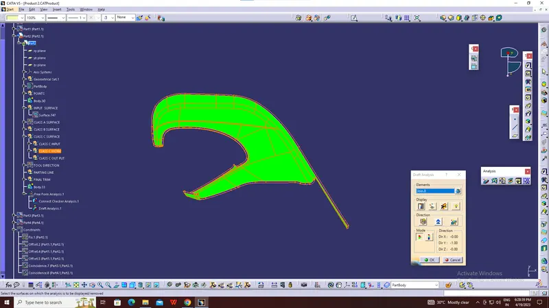
completed design in various orientations (Isometric, Front, Side, and Top View)
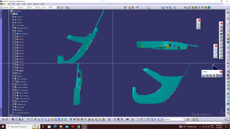
C)OUTER MAP POCKET:
GIVEN CLASS A SURFACE
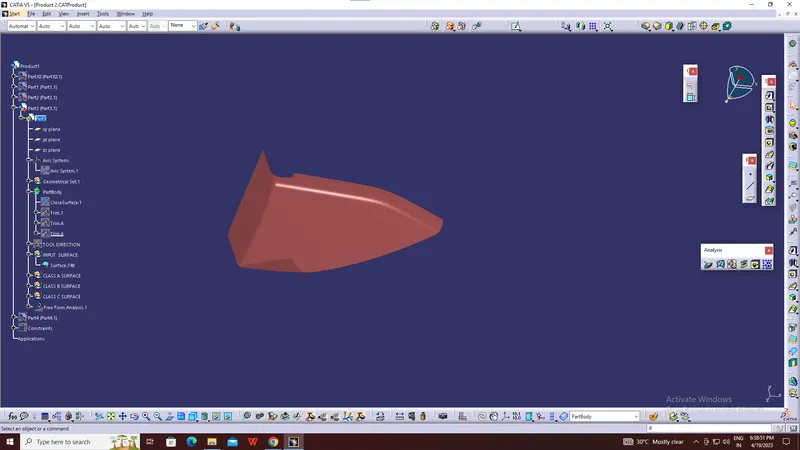
Tooling Axis :
Class-A surface is first analyzed to create the tooling axis. where the molds pull apart in injection molding. Tooling direction is essential for plastic product design as it decides the direction for mold separation.
To create the tooling axis first we have to check the best suitable direction for tooling by using the compass. the y direction is suitable for creating the tooling axis because in the y direction most of the surfaces are clearing while performing draft analysis. Generally tooling axis is created using bisecting line method but here A line normal to the surface is created in the y direction and considered the tooling axis.
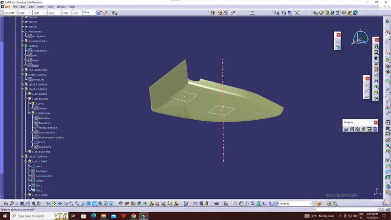
CREATION OF CLASS B SURFACE:
In this component Creation of the class B surface first, we have to offset the entire model by 2.5mm outward some of the surfaces give offset error and ask for offset without these subelements click okay and work on the incomplete surfaces by using the multi-section surface command, sweep and different commands used to complete the class B surface.
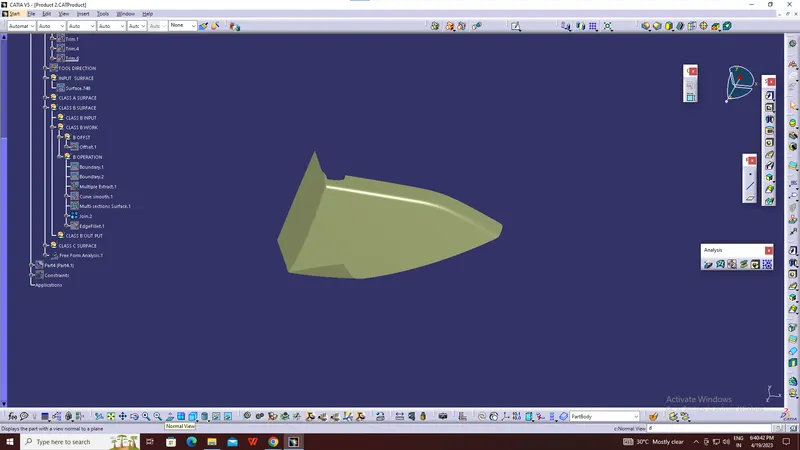
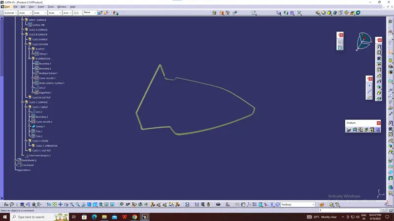
Class B OFFSET
CREATION OF CLASS C SURFACE:
We first extract the edges from the Class A surface with the help of the multi extract or boundary command which we create the path for a sweep for class C
like this, we have to create all separate sweeps and join them together. once all the sweeps are joined together we created a class c surface.
DRAFT ANALYSIS :
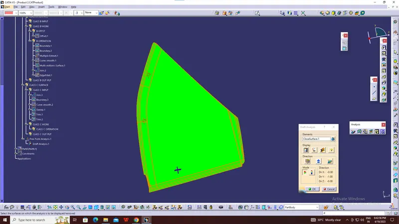
The Draft Analysis is a command that enables you to detect if the part you drafted will be easily removed. This type of analysis is performed based on colour ranges identifying zones on the analysed element where the deviation from the draft direction at any point, corresponds to specified values.
Draft analysis is done after determining the tooling axis, draft analysis is used to check whether the minimum draft (3 degrees) is maintained or not.
- Procedure for performing the draft analysis are as follows
- Change the view mode of the component to be in customized parameter mode and then select the shading mode as materials.
- Then open the featured draft analysis tool from the insert menu.
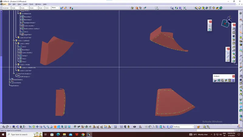
completed design in various orientations (Isometric, Front, Side, and Top View)
D)INNER MAP POCKET:
GIVEN CLASS A SURFACE
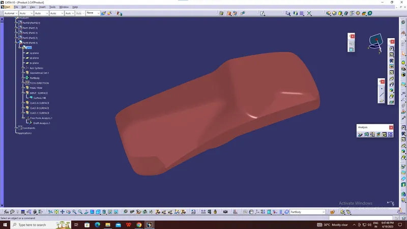
Tooling Axis :
Class-A surface is first analyzed to create the tooling axis. where the molds pull apart in injection molding. Tooling direction is essential for plastic product design as it decides the direction for mold separation.
To create the tooling axis first we have to check the best suitable direction for tooling by using the compass. the y direction is suitable for creating the tooling axis because in the y direction most of the surfaces are clearing while performing draft analysis. Generally tooling axis is created using bisecting line method but here A line normal to the surface is created in the y direction and considered the tooling axis.
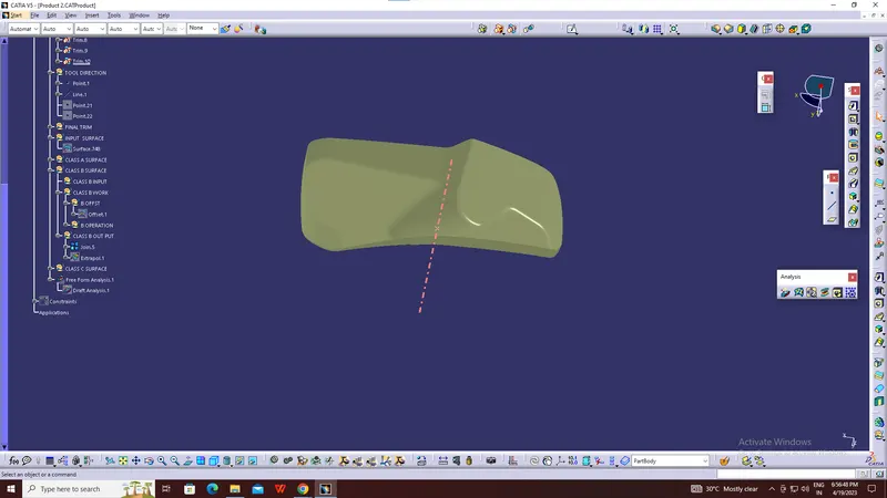
CREATION OF CLASS B SURFACE:
In this component Creation of the class B surface first, we have to offset the entire model by 2.5mm outward some of the surfaces give offset error and ask for offset without these subelements click okay and work on the incomplete surfaces by using the multi-section surface command, sweep and different commands used to complete the class B surface.
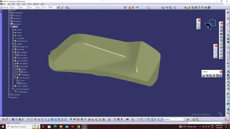
Class B OFFSET
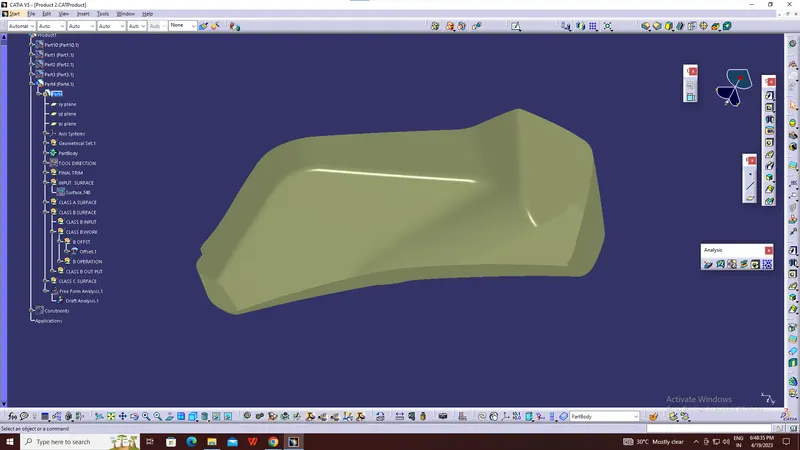
CREATION OF CLASS C SURFACE:
We first extract the edges from the Class A surface with the help of the multi extract or boundary command which we create the path for a sweep for class C
Solid component.
DRAFT ANALYSIS :
The Draft Analysis is a command that enables you to detect if the part you drafted will be easily removed. This type of analysis is performed based on colour ranges identifying zones on the analysed element where the deviation from the draft direction at any point, corresponds to specified values.
Draft analysis is done after determining the tooling axis, draft analysis is used to check whether the minimum draft (3 degrees) is maintained or not.
- Procedure for performing the draft analysis are as follows
- Change the view mode of the component to be in customized parameter mode and then select the shading mode as materials.
- Then open the featured draft analysis tool from the insert menu.
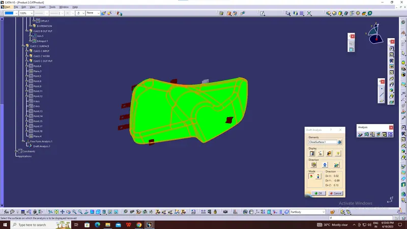
completed design in various orientations (Isometric, Front, Side, and Top View)
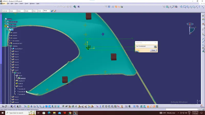
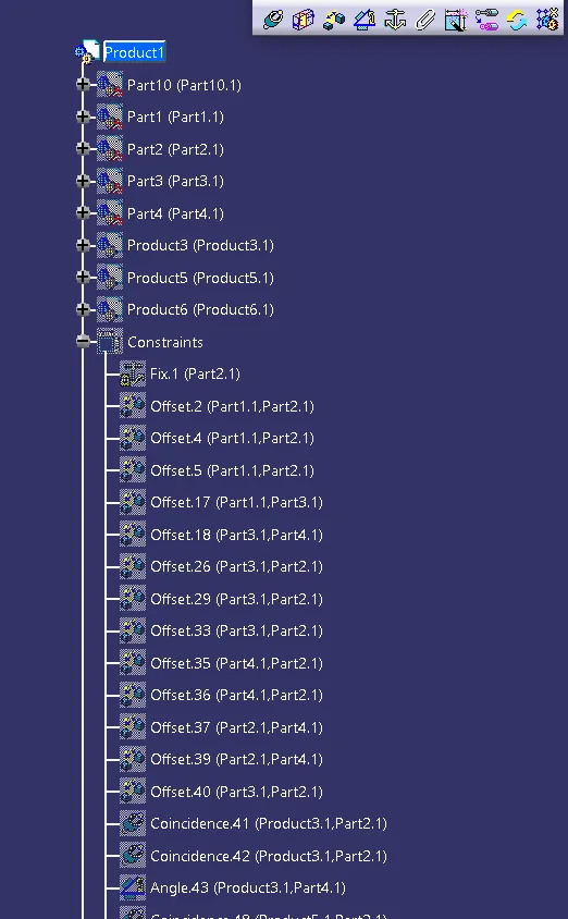
Iso-constrained
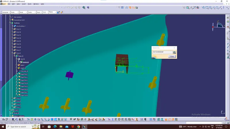
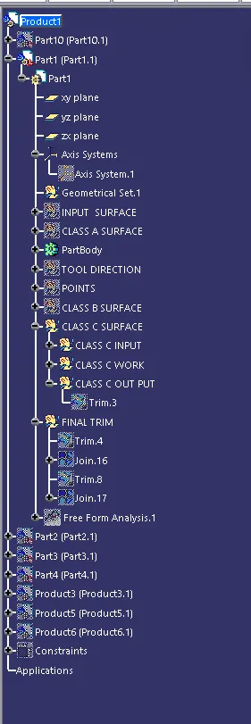
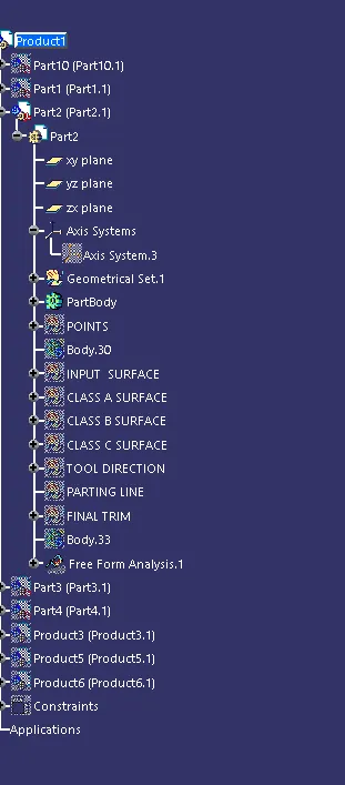
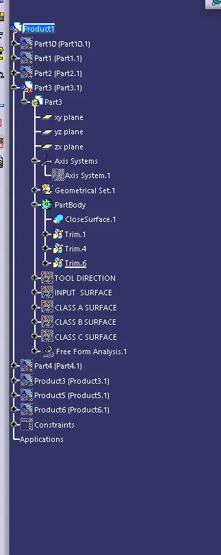
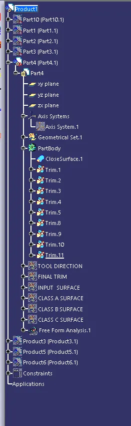
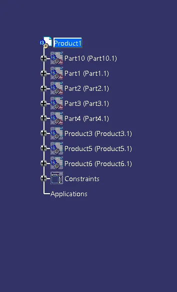
Tree structure
DOG HOUSE DESIGN:
Dog house: Dog house is an engineering feature used in the plastic trim design. Dog houses are used as supporting features. Sometimes other engineering features like snaps; locators, etc. are mounded on them to increase their strength. Dog house and other engineering Features are built on B-surface.
Design rules for Dog house creation
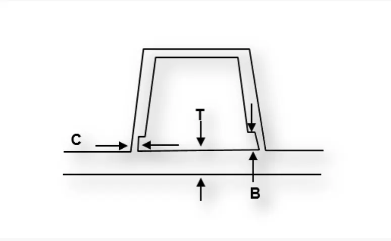
"C" is where the doghouse contacts the backside of the surface
Doghouse wall thickness at the intersection of the part wall ( C ) should be 40% or less than the main wall stock ( T ).
The height of ( B ) should be between 3.0 – 6.0 mm
Dog house design procedure by considering the design rules:
Extract the surface on which we want to create the dog house and create a sketch on a plane
LOCATORS
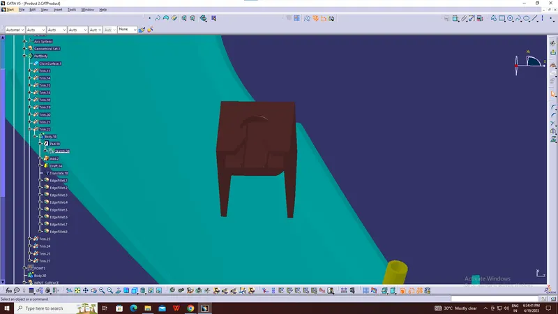
- Extract the surface that we going to create locator
- Use positiioned sketch and draw a locator sketch
- Use pad commands for the sketch to till we required
- Draft the locator for minimum of 0.5 degree
- Add fillet 0.5mm o all faces
- Assemble the locator to lower subtrate solid
- Maintain a 50mm minimum between two locator
- Translate the locator to wherever we need
- Trim the all heat stakes with lowersubstrate solid
- Maintian a height more than heat stake
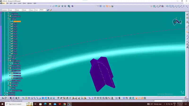
Sketch Plane is made in the tooling axis direction.
Height = 20 mm
Wall Thickness = 1.3 mm
Draft Angle = 0.5°
Chamfer = 3 mm, 45°
Fillet 0.3 mm & 3 mm
HEAT STAKES
Heatstakes is known as thermoplastic staking is the process of joining two dissimilar metals together
- Extract the surface that we going to create heat stake
- Use positiioned sketch and draw a heat stakes sketch
- Use pad commands for the sketch to till we required
- Draft the stakes minimum of 0.5 degree
- Add fillet 0.5mm o all faces
- Assemble the heat stake to lower subtrate solid
- Maintain a 50mm minimum between two heat stakes
- Translate the heatstakes to wherever we need
- Trim the all heat stakes with lowersubstrate solid
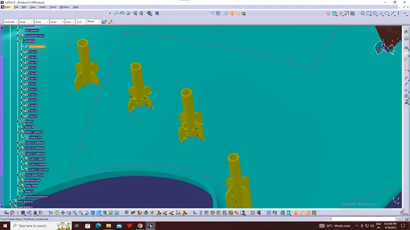
Sketch Plane is made in the tooling axis direction.
The length of heat stakes should be at least 5 mm lesser than locators, L = 15mm
Radius, ID = 5mm, OD = 7 mm
Draft Angle = 0.5°
FLANGE
Create a flange for attachment of heatstakes and locators at lower substrate.
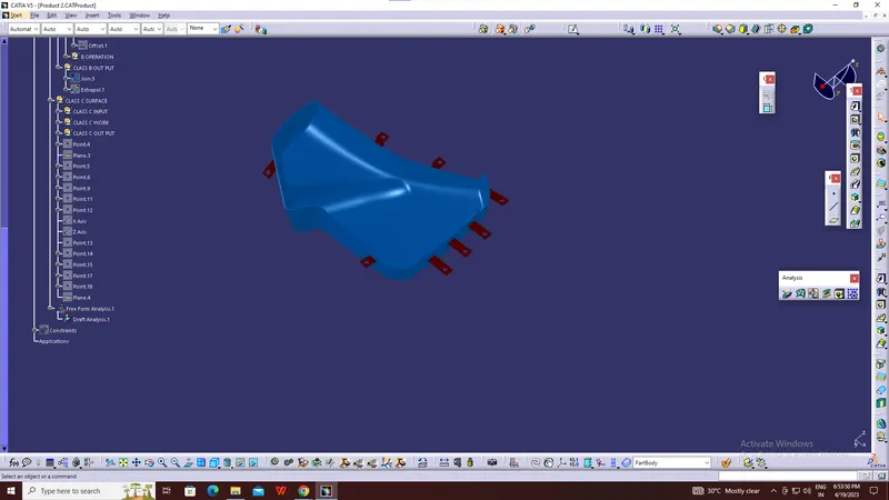
FINAL PART BODY
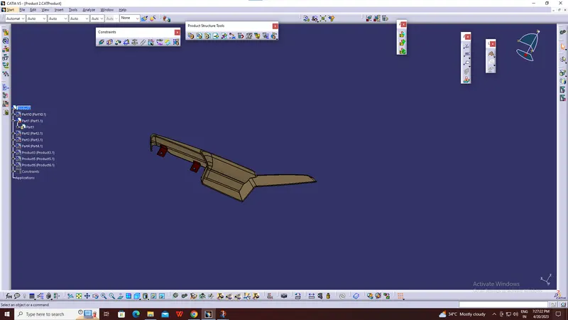
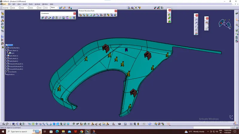
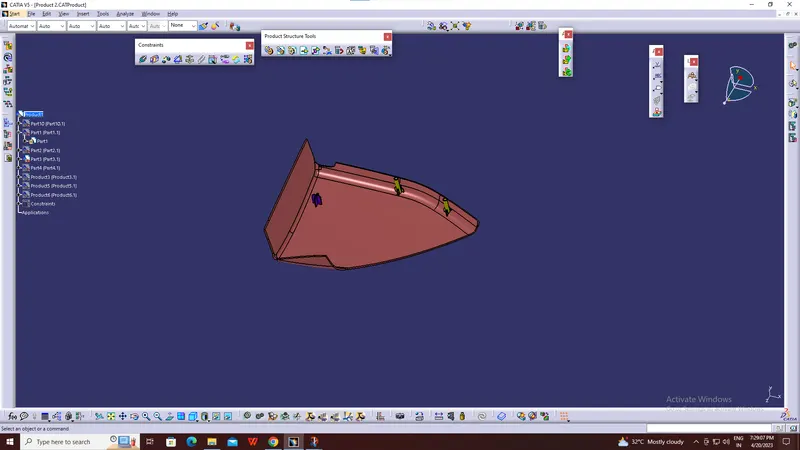
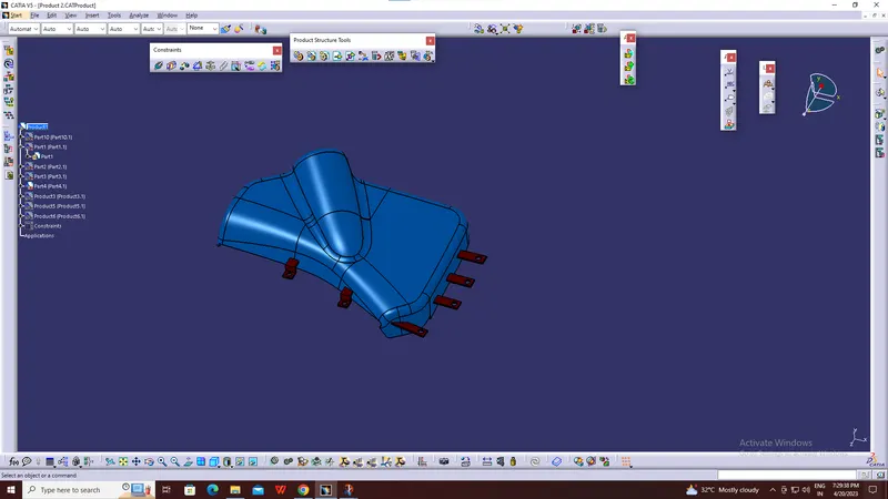
FINAL OUTPUT