Week 12- Final project
AIM:
To develop the Door Trim panel
OBJECTIVE:
- Creation of CAD model considering following inputs as like in OEM and tier1 companies
- a) Class A surface
- b) Nominal thickness : Refer master sections
- c) Attachment strategy :
- Find a attachment strategy for the door panel complete work.
- Use Push pin with Dog house for Lower substrate – Door panel attachment
- Use heat stakes for part to part attachment
Output required:
- Create thickened part using master section for reference
- Create the mounting features as per design guidelines in the industry and with master sections
- Apply material details :
- Draft analysis & Tooling analysis
- Creation of parting lines and check tooling feasibility
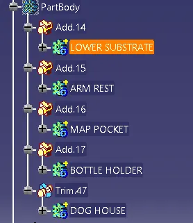
NEED TO CREATE SUB ASSEMBLY BODIES:
1.Lower substrate
2.Map pocket
3.Bottle holder
4.arm rest
1.LOWER SUBSTRATE:
A SURFACE DRAFT ANALAYSIS:
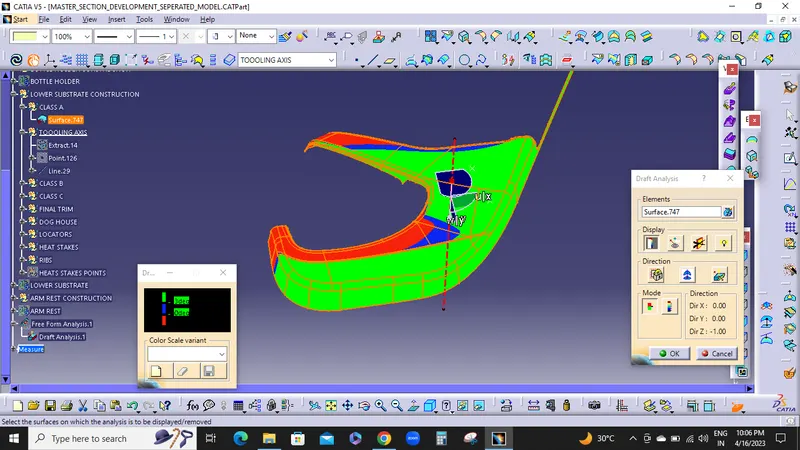
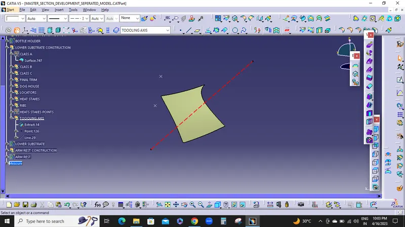
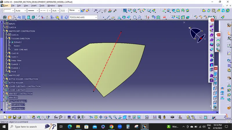
TOOLING AXIS:
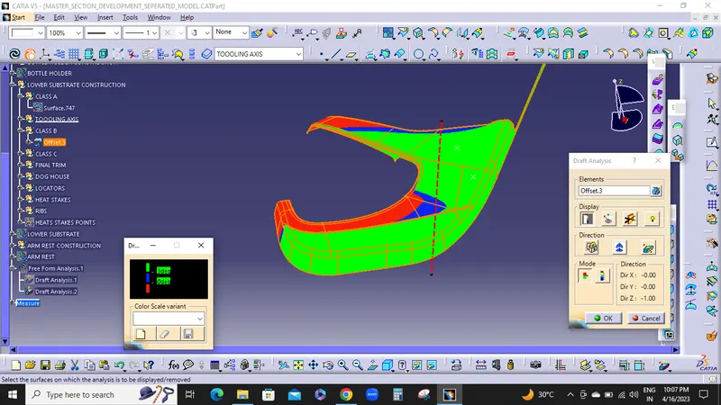
B SURFACE DARFT ANALYSIS:
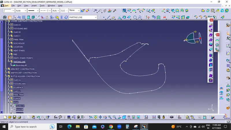
PARTING LINE:
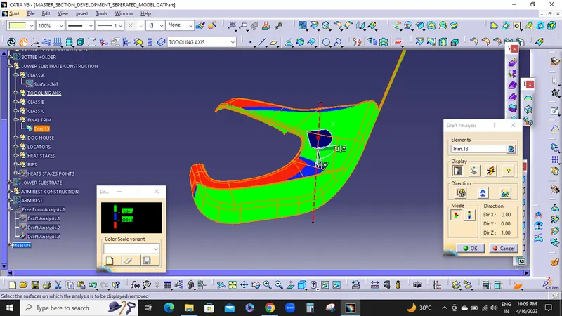
FINAL TRIM DRAFT ANALYSIS:
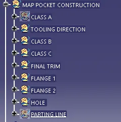
2.MAP POCKET
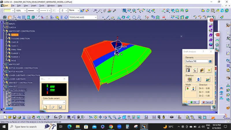
A SURFACE DRAFT ANALYSIS:
TOOLING AXIS:
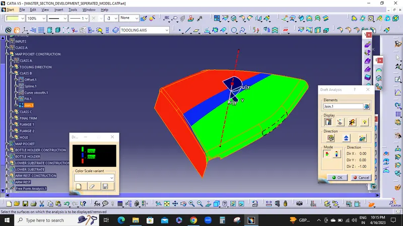
B SURFACE DRAFT ANALYSIS:
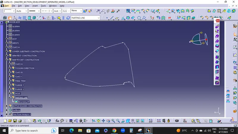
PARTING LINE:
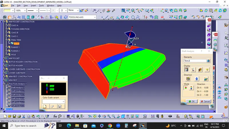
FINAL TRIM DRAFT ANALYSIS:
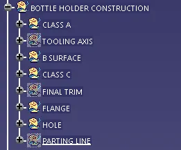
3.BOTTLE HOLDER:
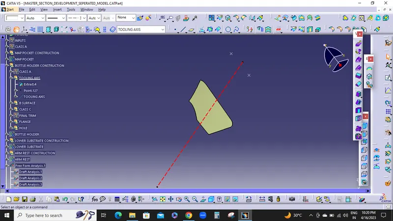
TOOLING AXIS;
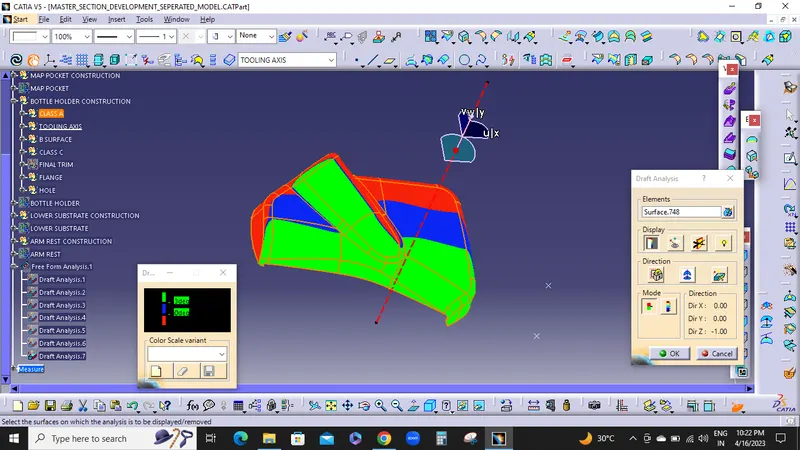
A SURFACE DRAFT ANALYSIS:
B SURFACE DRAFT ANALYSIS:
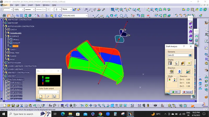
PARTING LINE:
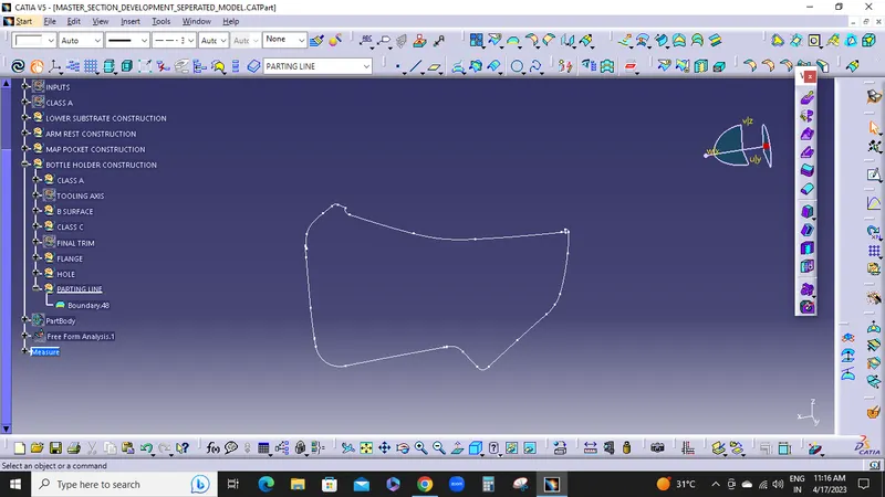
FINAL TRIM DRAFT ANALYSIS:
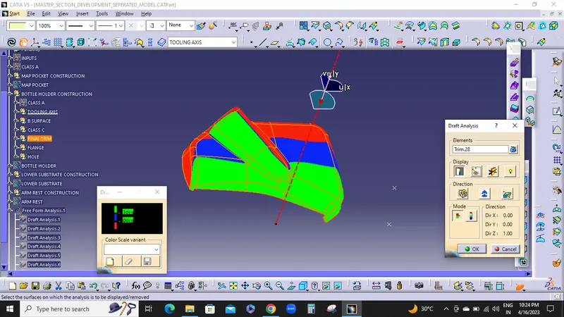
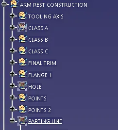
4,ARM REST:
TOOLING AXIS:
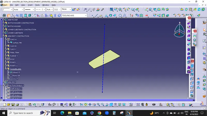
A SURFACE DRAFT ANALYSIS;
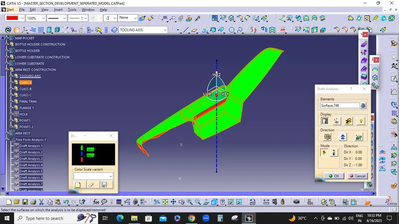
B SURFACE DRAFT ANALYSIS:
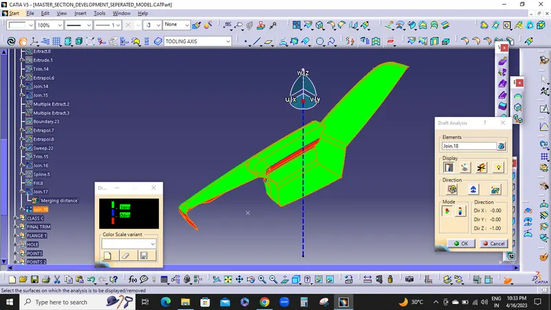
PARTING LINE:
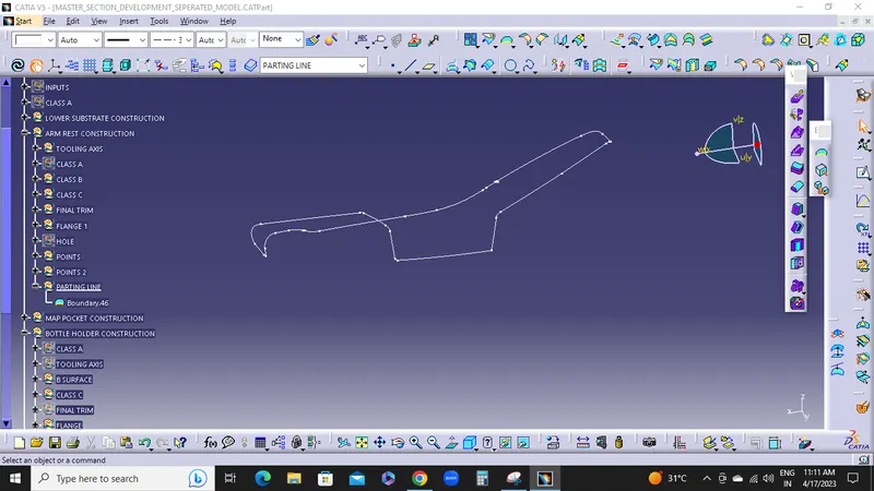
FINAL BODY DRAFT ANALYSIS:
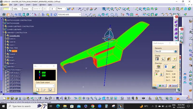
FLIP DIRECTION DRAFT ANALYSIS:
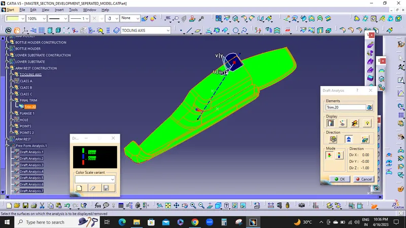
ATTACHEMENT FEATURES:
1.DOG HOUSES
2. HEAT STAKES
3.SUPPORTING RIBS
4.FOUR WAY LOCATORS
1.DOG HOUSE:
Dog house is an engineering feature used in plastic trim design. Dog houses are used as supporting feature. Sometimes other engineering features like snaps; locators etc. are mounded on them to increase their strength. Dog houses are subjected to draft analysis to prevent breakage of the component during ejection from mould cavity. Dog house and other engineering components are built on B-surface.
DRAFT ANGLE:
Tooling must be cleared for easy ejection of the component, from the core cavity. In order to clear tooling certain value of draft is given to the component. Minimum of 1.5 - 3deg is provides on all plastic components.
DRAFT ANALYSIS ON TOOLING AXIS:
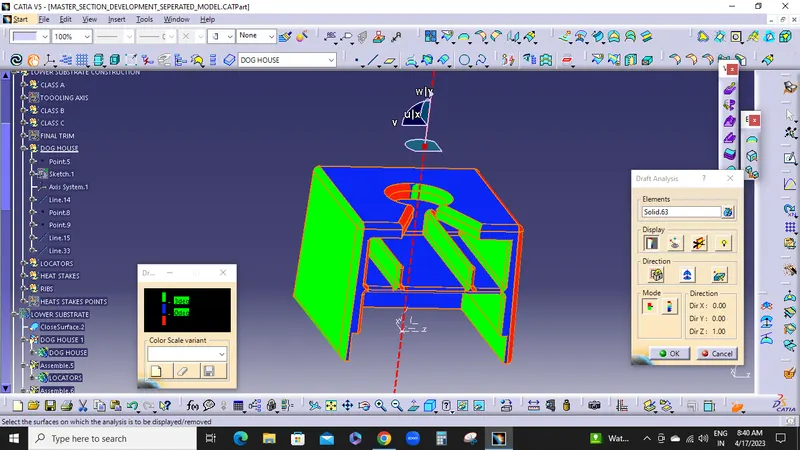
MAXIMUM DRAFT ANALYSIS - 3 degree
MINIMUM DRAFT ANALYSIS - 0 degree
SIDE CORE AXIS DRAFT ANALYSIS:
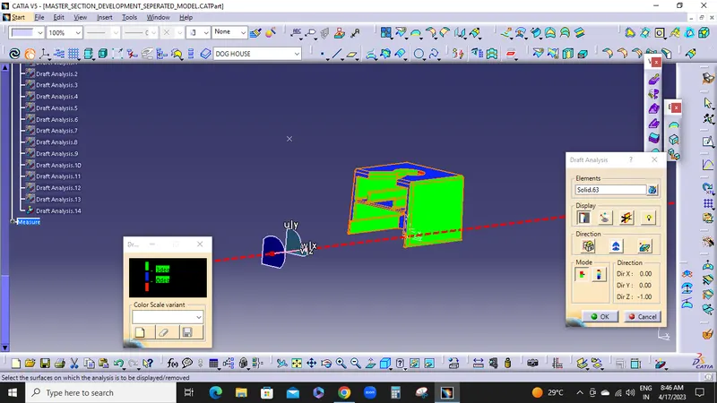
MAXIMUM DRAFT ANALYSIS - 3 degree
MINIMUM DRAFT ANALYSIS - 0 degree
FILLETS:
Fillet on the inner side = 0.25 * Thickness of the plastic material
Fillet on the outer side = 1.25 * Thickness of the plastic material
Fillet on the coring edges = 0.25 * Thickness of the plastic material
Coring thickness = 0.40 * Thickness of the plastic material
HEAT STAKES & SUPPROTING RIBS:
Heat staking is the process to attach two separate components together by melting the base plastic material into a shape that will hold the secondary component. It’s a permanent attachment method that does not require any additional material such as an adhesive or a solvent to make the permanent bond. The only addition is the heat applied to melt the plastic and a tool to shape the plastic to form the mechanical connection.
REASONS FOR HEAT STAKING:
1.Mutiple staking shapes for different benefits.
2.Excellent durability.
3.No extra materials are needed.
4.Increased efficiency.
5.Easy Maintenance.
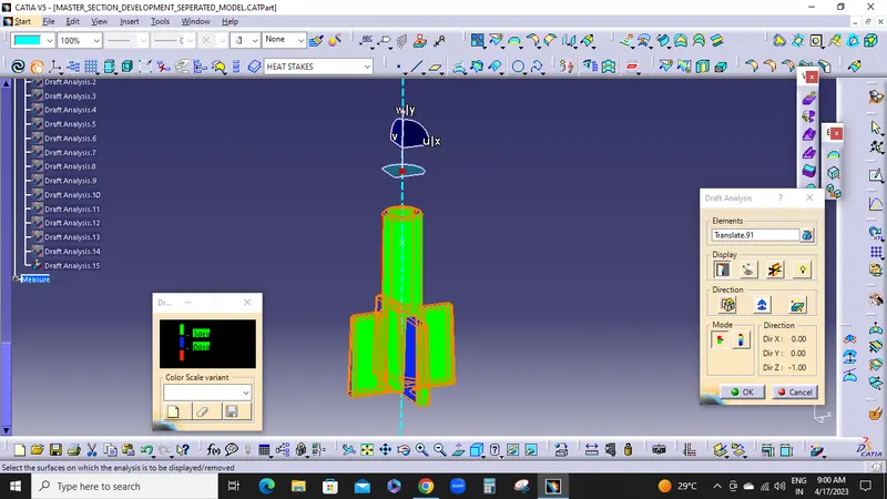
DRFAT ANALYSIS:
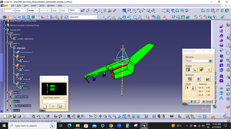
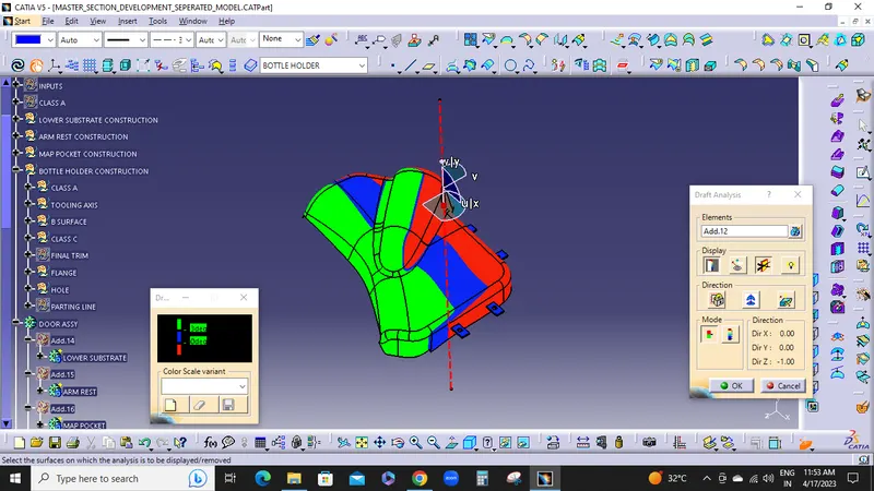
Draft on heat stakes - 0.5 degree
Draft on ribs - 0.5 degree
MAXIMUM DRAFT ANALYSIS - 3 degree
MINIMUM DRAFT ANALYSIS - 0 degree
FOUR WAY LOCATORS:
4-way mean you prevent movement at 2 axes (+X, -X, +Y and -Y) on the plane. Generally, you have cylindrical pin on the fixture and circular hole at workpiece part.
- 40% of mainbody thickness
- Draft angle 0.5 degree
- Chamfer value is 2mm & 45 degree
- Edge fillet value is 1mm or 3mm
DRAFT ANALYSIS ON FOUR WAY LOCATORS:
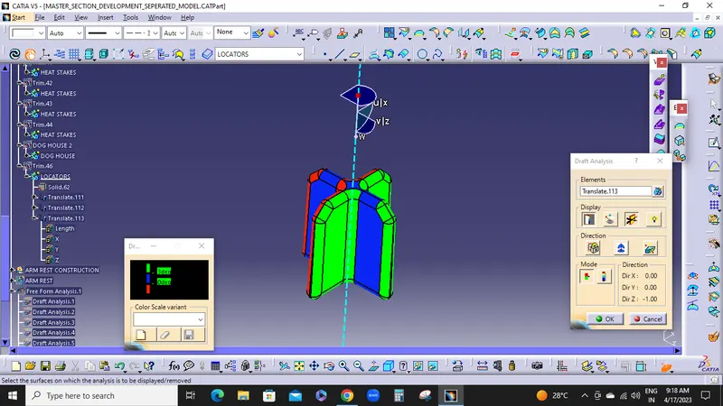
MAXIMUM DRAFT ANALYSIS - 3 degree
MINIMUM DRAFT ANALYSIS - 0 degree
FLANGE:
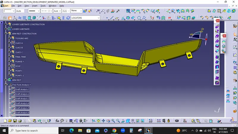
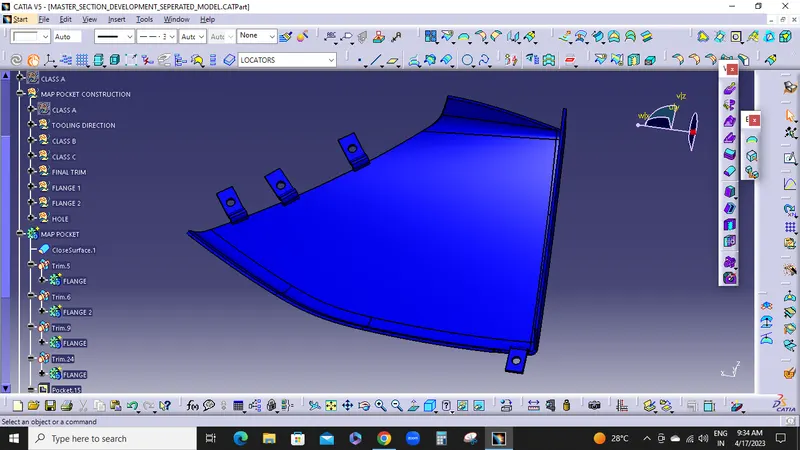
Procedure to create flanges and heat stakes for every part, from given master sections. Use multiple extract to obtain required guide curve and sweep profile for flange top surface. Use sweep option to create a surface from below and top obtained multiple extracts. Use extrapolate to extend the surface according to master section and close them to create a solid body in a new body. Create holes and flat surfaces for heat stake. This way all flanges have to create. In some areas if master secion is not given and flanges are required for those areas then create flanges without master section maintaining engineering standerds
ARM FLANGES:
DRAFT ANALYSIS:
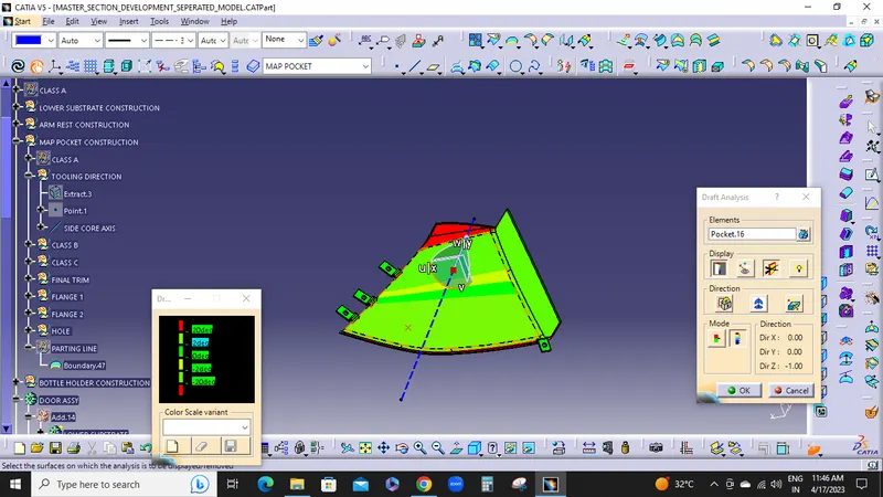
MAP POCKET FLANGES:
DRAFT ANALYSIS:
BOTTLE HOLDER FLANGES:
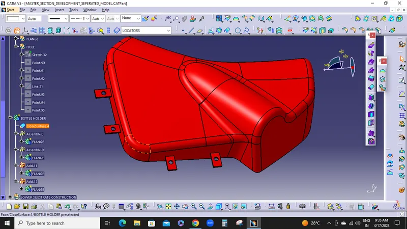
DRAFT ANALYSIS:
LOWER SUBSTRATE WITH ALL ATTACHEMENT FEATURES:
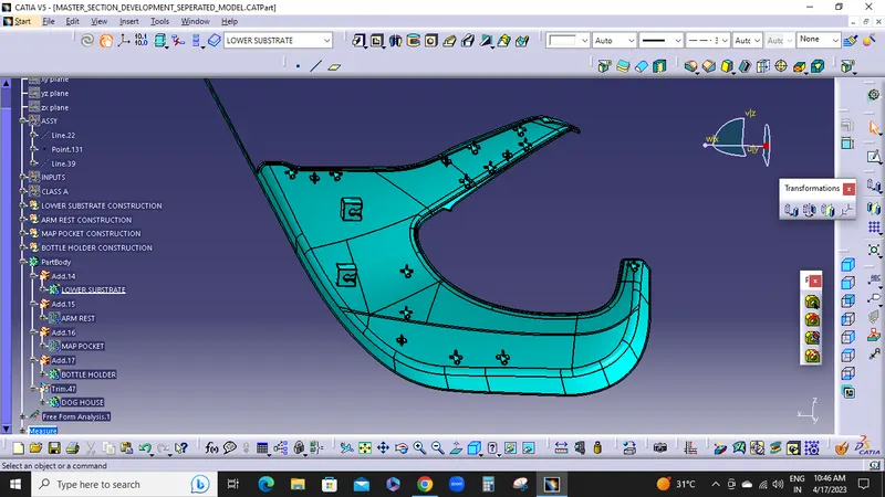
DRAFT ANALYSIS:
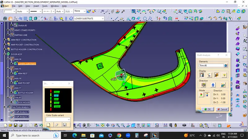
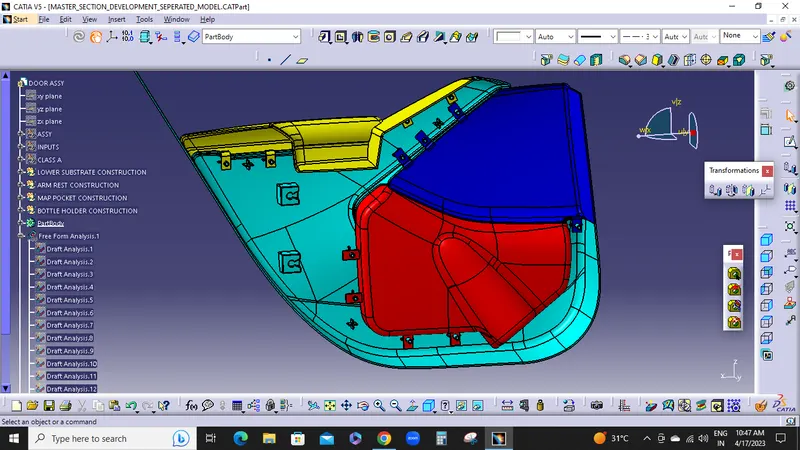
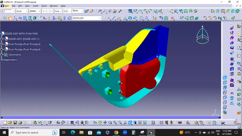
FINAL DOOR ASSY BODY:
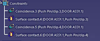
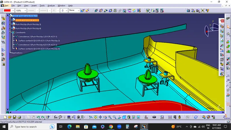
NOW,ASSEMBLE THE DOG HOUSE TO PUSH PINS:
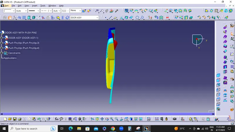
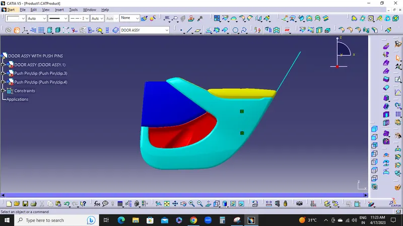
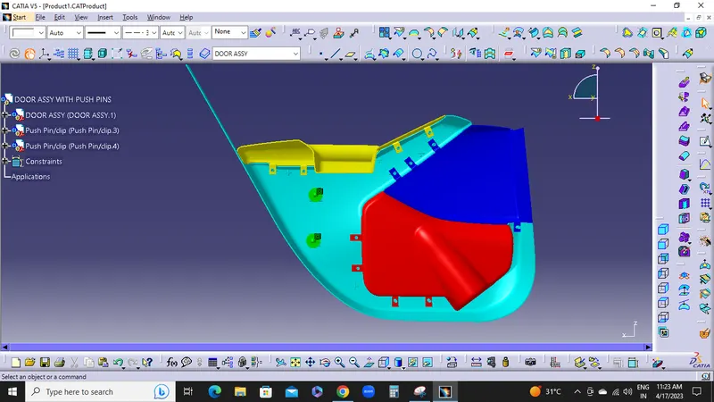
ALL VIEWS:
ISOMETRIC VIEW:
TOP VIEW:
LEFT SIDE VIEW:
RIGHT SIDE VIEW:
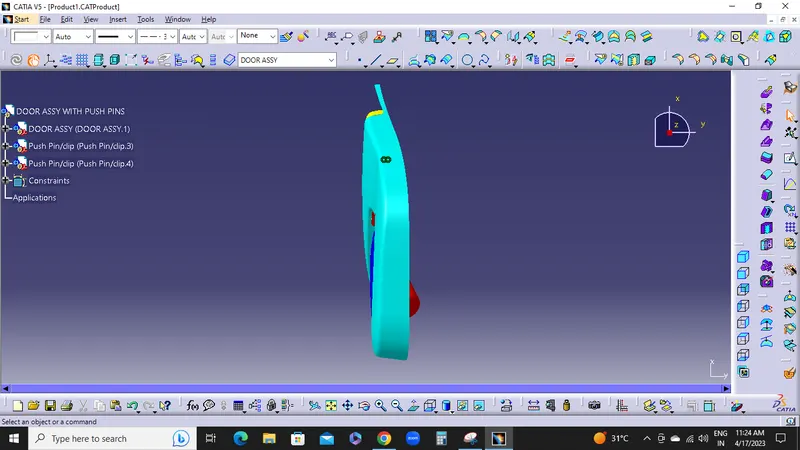
BOTTOM SIDE VIEW:
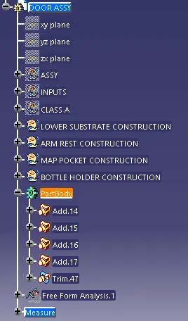
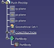
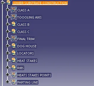
TREE STRUCTURES:
CONCLUSION:
NOW,FINALLY DEVELOPED THE DOOR TRIM PANEL