Week 12- Final project
WE ARE GIVEN THE CLASS A SURFACES FOR THE FOLLOWING COMPONENT:
A. LOWER SUBSTRATE
B. ARM REST
C. MAP POCKET
D. BOTTLE HOLDER
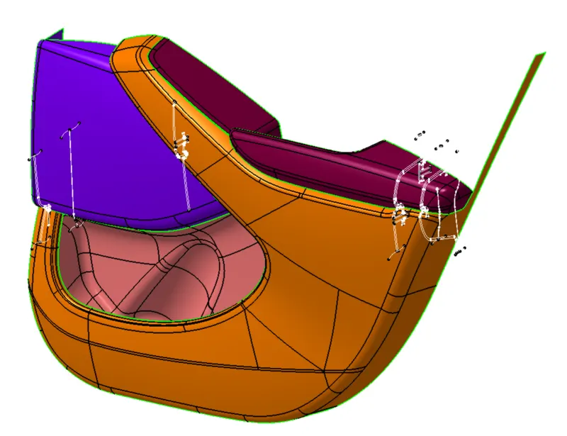
Fig: given input class A surfaces with the master sections:
TAKING THE CASE OF LOWER SUBSTRATE, THE CLASS B AND C SURFACES ARE DEFINED
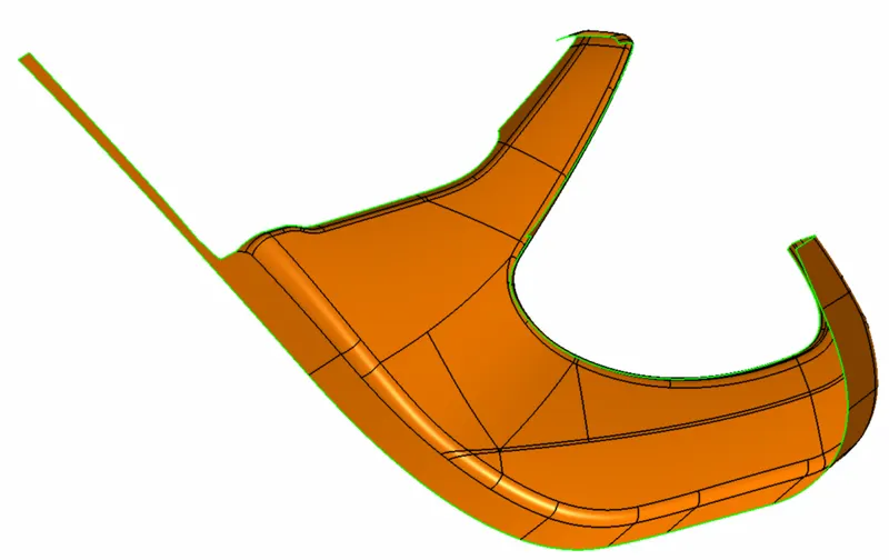
Fig 1 : Given Class A for lower substrate
- Depending on the given class A surfaces, we might need to fix the surface if there are some error patches. once this is done we can proceed for the draft analysis of it and proceed to class B and C surface creation
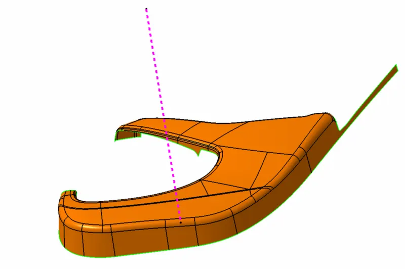
Fig 2: creation of the tooling axis based on the master section provided
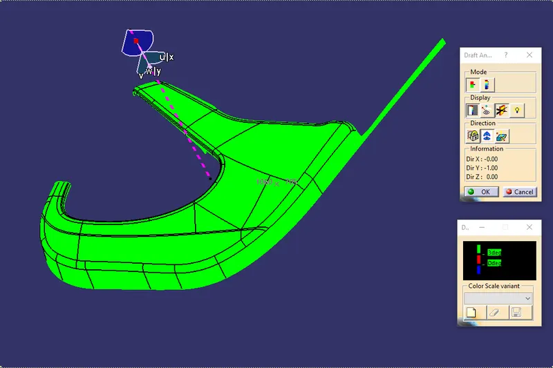
- Checking the feasibility of the tooling axis for the 3 degree draft. The surface is good to go with
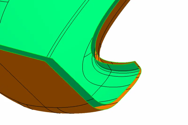
Fig: Class B surface is in green
- The class B surface is created by offsetting the class A surface for 2.5 mm as per the master section guidelines. Similarly, the error patches can be fixed using multi-section, fillet creation or sweep surface commands depending on the surfaces. It is upto the design engineer for which path they consider is the optimum one (there are a plethora of them).
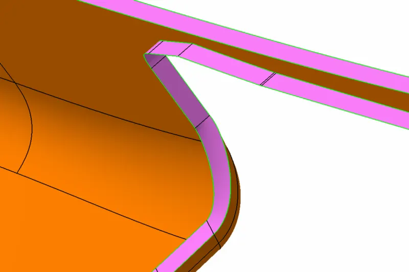
Fig: C surface creation using sweep command using the class A surface edge extracts.
These are divided into 2:
a. sweeps that are drafted along the tooling direction
b. sweeps that are perpendicular to the surface being sweeped from
- A given class A surface can have both these cases. In case of patches that cannot be sweeped, using multisection commands or a different subset of sweep command can prove to be useful.
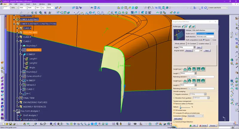
Fig: Sweep C surface under the draft direction subset
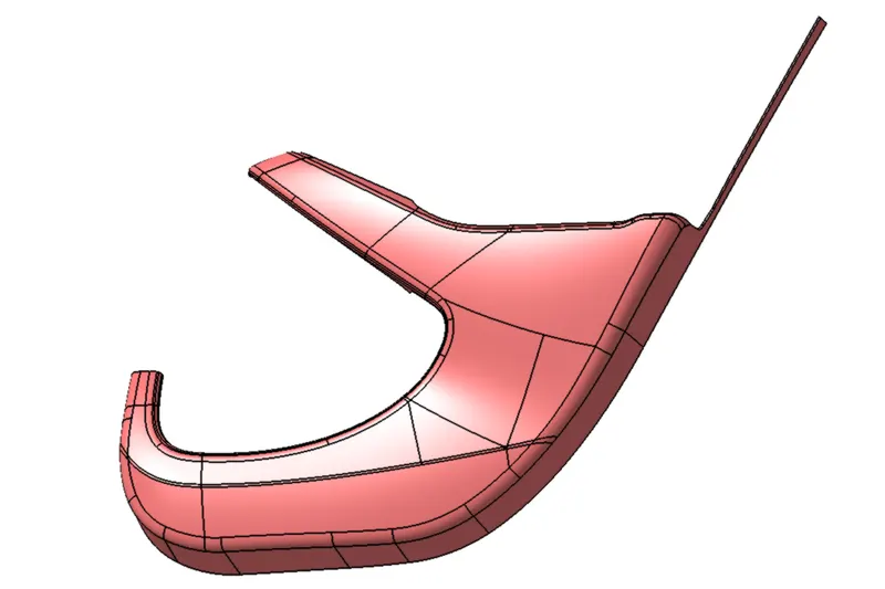
Fig: The creation of the part body using the closed surface command on the trim between the class B, C and A surfaces
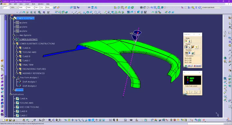
Fig: Draft analysis for the lower substrate (the given angle of 2.5 degree is taken due to the surface limitations)
HEAT STAKE/LOCATOR:
- The heat stake and locators are defined based on reference points
- Taking a multiple extract of the relevant surfaces, extract the entire corresponding edge
- Using parallel curve command, deine the reference points onto it
- Sketch both the locator and the heat stake at any two selected points
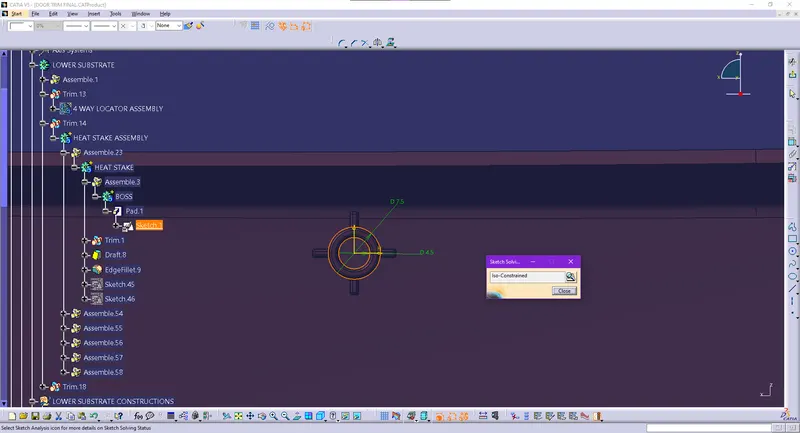
Fig: Heat stake sketch
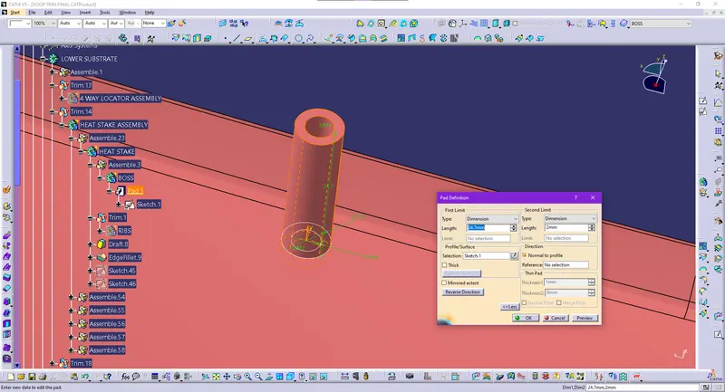
Fig: defining heat stake (boss subpart) using pad
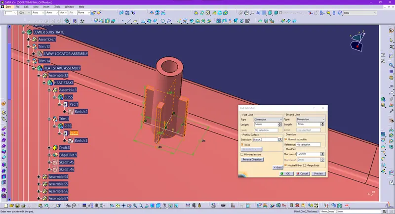
Fig: Defining rib subpart using pad
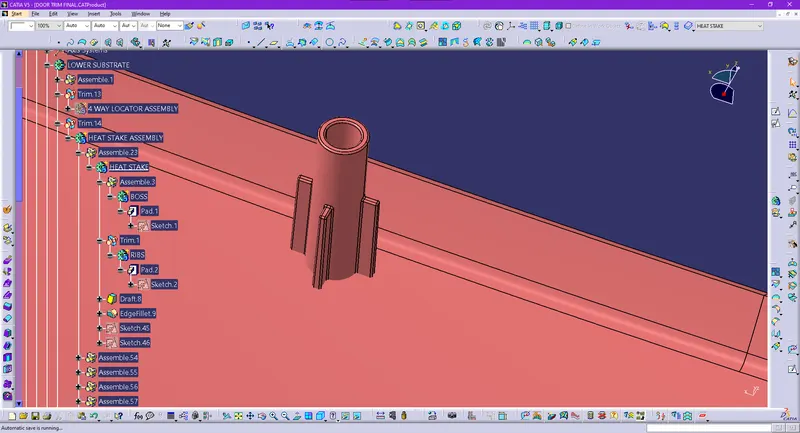
Fig: union trim of both subparts to define the heat stake
- the heat stake is then drafted for 0.5 deg for all the relevant faces and smoothen using edge-fillets.
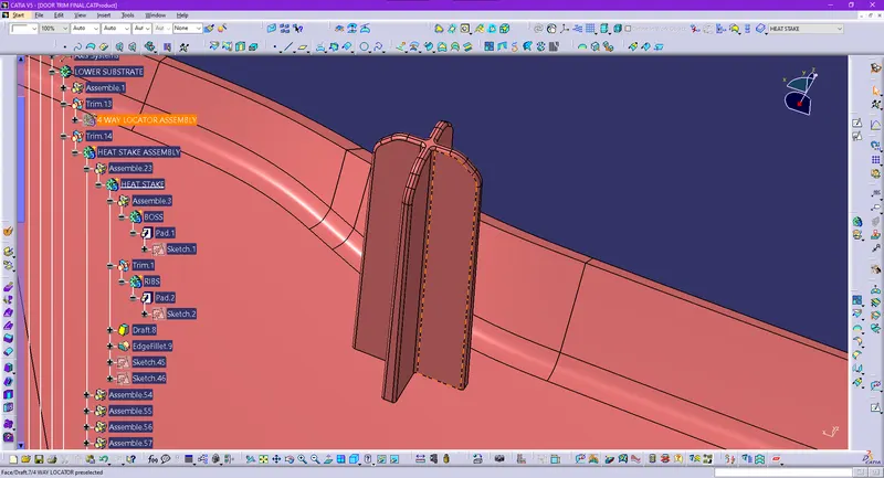
Fig: Locator using pad feature
- The locator as mentioned earlier is defined similar to how the heat stake is defined.
DOGHOUSE:
- The doghouse is created by first extruding the base sketch
- using a 20mm offset of a planar surface, trim bith these surfaces
- using the thick surface command in the PD workbench, thicken the component by 2.5mm
- make sure that there is excess to the surface than the dimensions before extrusion or, extrapolate the base extrude so that later to get a smooth face, the split command can be applied to get the design dimension.
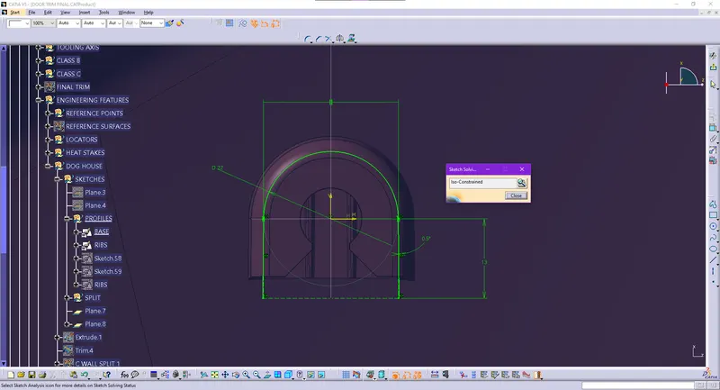
Fig: base sketch (the lines are extended by 3mm here)
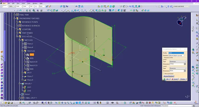
Fig: extruded base for the doghouse
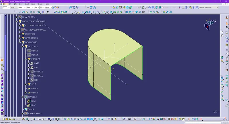
Fig: trim of the extruded base witht the planar offset surface
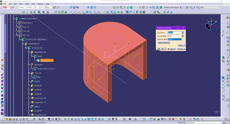
Fig: thickened part body (2.5mm thick)
- using the sketch for the ribs, pad the sketch using the thick option enabled (as the sketch contains open profiles)
- the pad should extend out the base part body so that it can be union-trimed
- split the front face with an offset plane for the design dimension and all the external faces can be drafted for the design draft of 1.5 deg along the main tooling axis
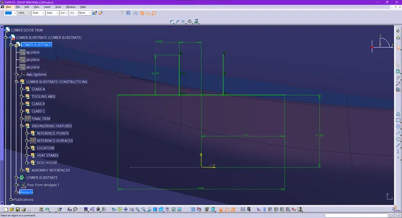
Fig: Rib sketch for the doghouse
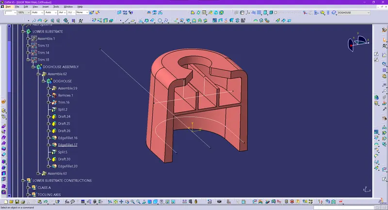
Fig: doghouse with all the faces drafted (external-1.5 deg/main tooling axis; internal-0.5 deg/side core tooling axis)
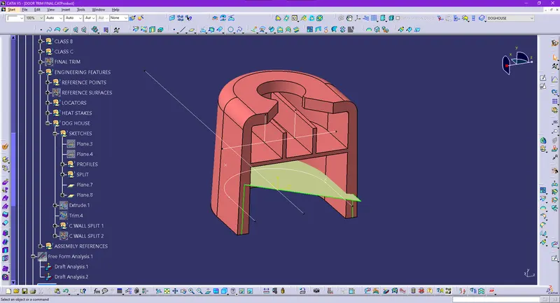
Fig: defining the teim surface for the undercut (with the c wall thickness of 40% of the nominla wall thickness---> 0.4 x 2.5 = 1.0mm)
- The undercut trim surface is defined by trimming the extract of the offset of the surface where the doghouse meets the main body (an offset of >= 3mm should be used) with the offset of the external surface extracts (1mm offset)
- this can be used to define the final trim for splitting to define the undercut
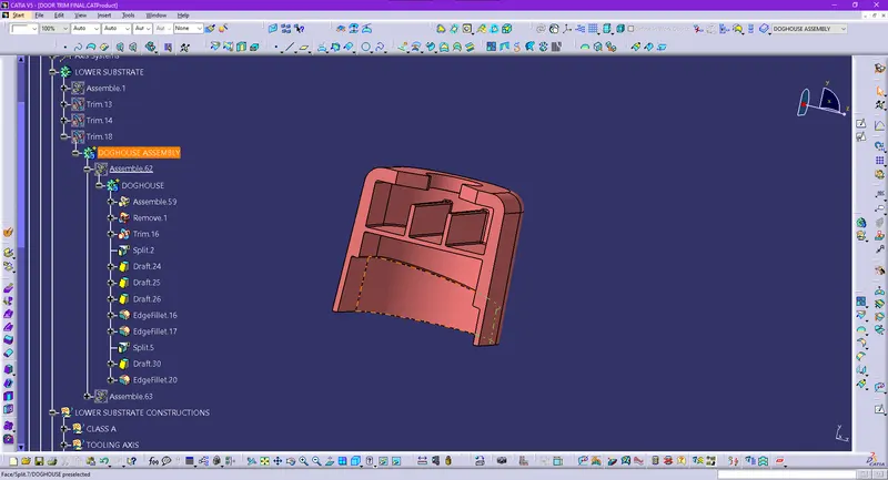
Fig: Doghouse with the undercut
- once the features are defined, using copy & paste commands and then translating them using point to point vector relations results in the placement of all the locators, heat stakes doghouses.
- the paste special method isn't used here to have more local control of the created features that can be levraged depending on the local requirements (for e.g. the rib subpart height for the heat stakes vary for each location due the curvilinear nature of the surfaces as well as the flanges)
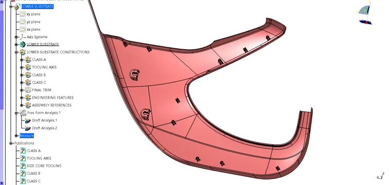
Fig: Lower subtrate with all the B-side features (doghouses, heat stakes and locators)
FLANGE:
The general method of flange creation involves:
- defining of the profile (referring the master-sections)
- defining the guide curves using the extract of the edges where the flanges are supposed to be defined
- sweeping the profile along the guide curve
- thickening the sweep for the given value from the master-sections
- splitting the thick part to define the design flanges
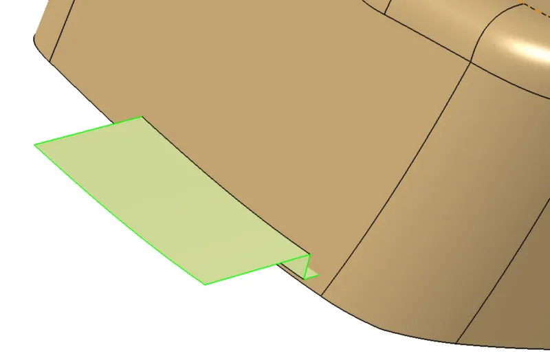
Fig: sweeping the profile along the guide curve
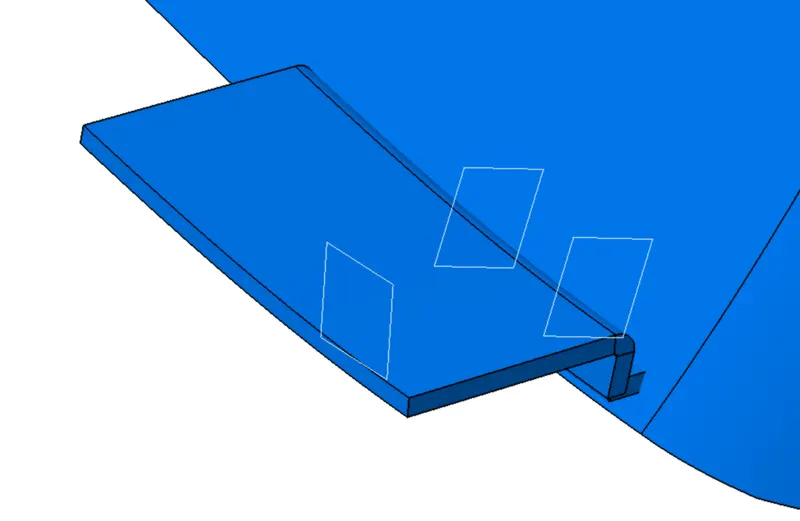
Fig: convert into a part body using thick surface command on PD workbench (2.5 mm thick)
The planes shown are used to slpit the flange to constraint the dimensions according to need
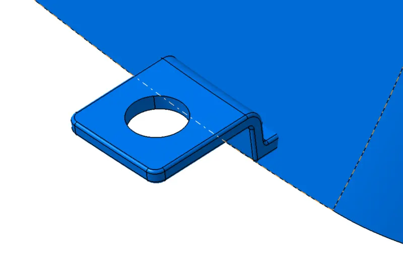
Fig: the split flange is then smoothened using edge fillets and a counterbore is created for each flange containing all the draft features as well as the dimensional variation depending on whether it is meant for the locator or the heat stake
DRAFT ANALYSIS:
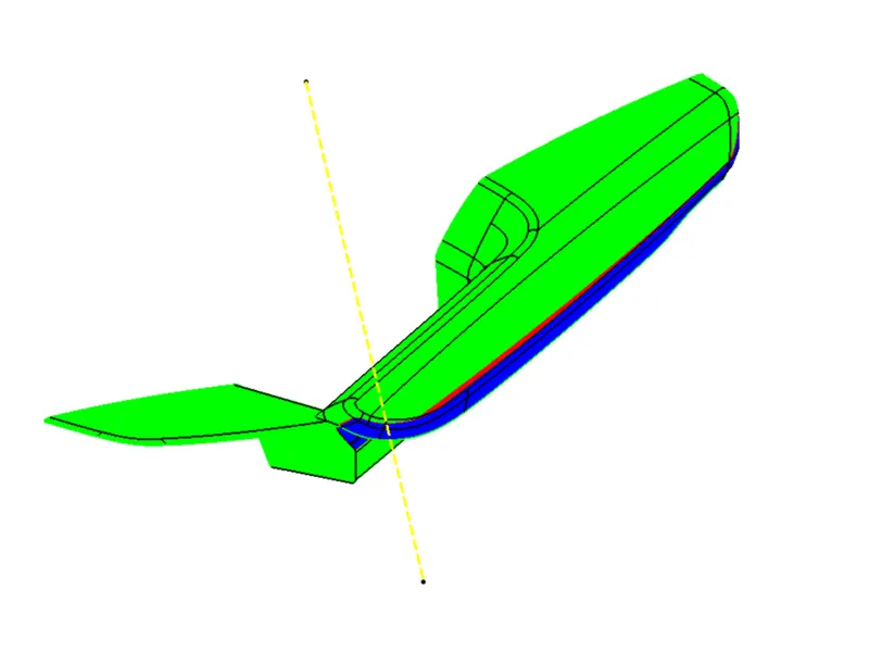
Fig: Class A arm rest (the nature of the surface renders the usage of more than one tooling direction)
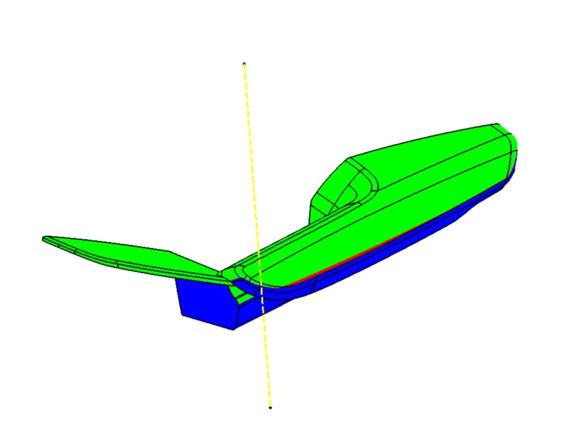
Fig: draft analysis for the arm rest component
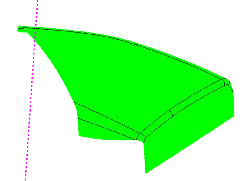
Fig: map pocket class A draft analysis - 3 deg
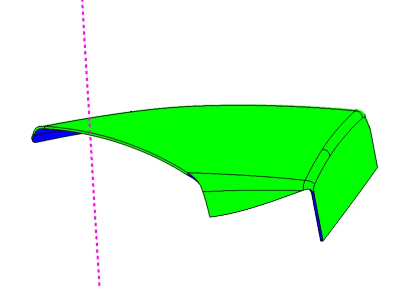
Fig: map pocket part draft analysis - 3 deg
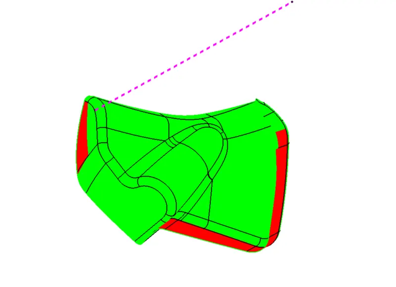
Fig: bottle holder class A draft analysis - 3 deg
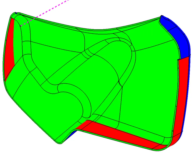
Fig: bottle holder part draft analysis - 3 deg
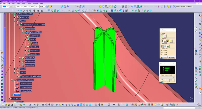
Fig: Locator draft analysis - 0.5 deg
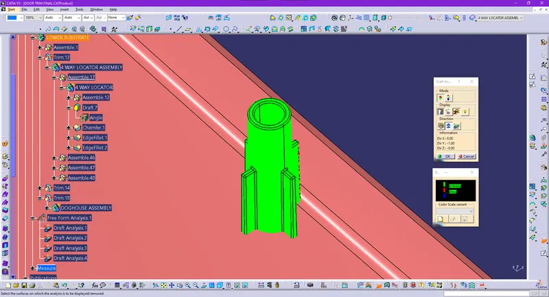
Fig: heat stake draft analysis - 0.5 deg
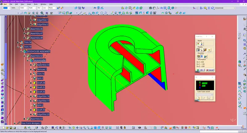
Fig: Doghouse draft analysis - 1.5 deg (main tooling axis)
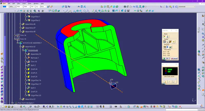
Fig: Doghouse draft analysis - 0.5 deg (side core tooling axis)
Once, all the parts are created with the b side features and flanges:
- Import all the parts into a .CATProduct document (assembly file)
- Using the published reference elemnents define the relevant contrains (fix, coincidence and offset in our case)
- Save the assembly file.
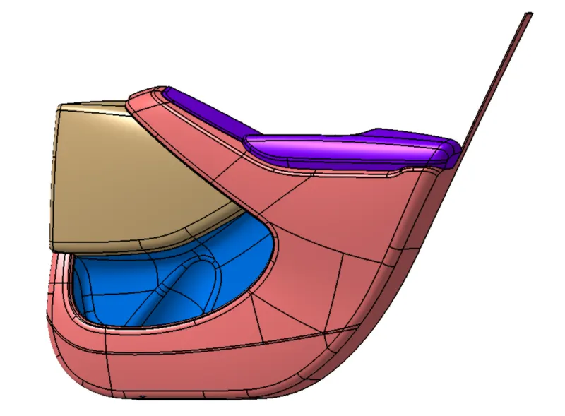
Fig: Door trim Lower Assembly (from the front)
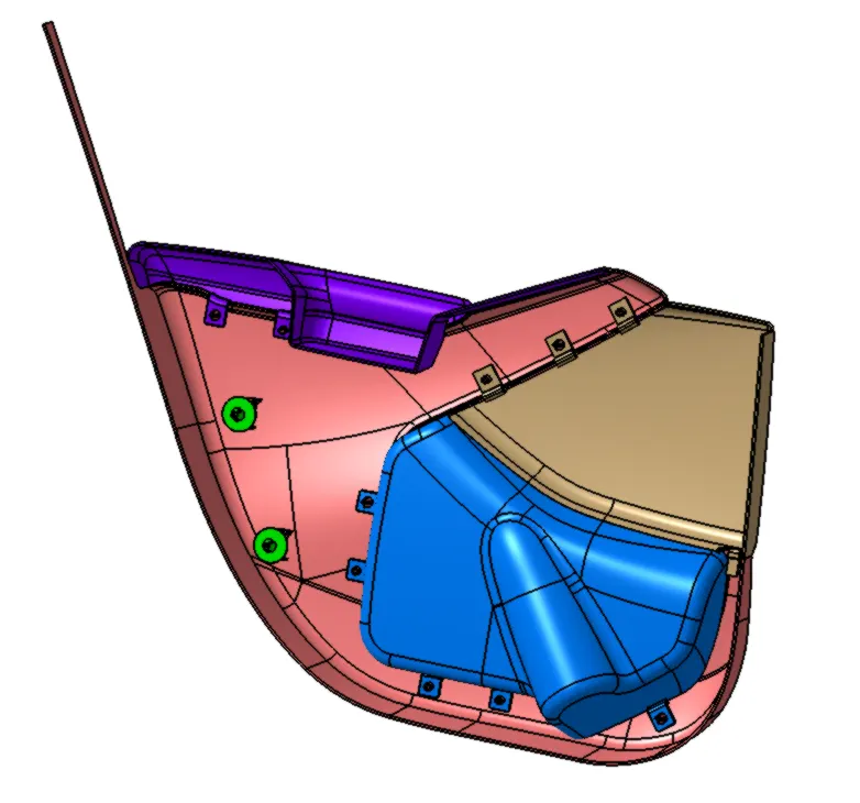
Fig: Door trim Lower Assembly (from the back)