Week 8 - Challenge 1 - Base Bracket Design
1a_Tooling axis report:
The process of selecting a tooling direction depends upon the path containing minimum drafting that is the tooling direction will consist of minimum drafting faces
With this assumption the plane that contains the maximum amount of projected area tentatively, has to be selected.
In the given scenario here are 3 cases along 3 orthogonal planes, based on the axis system that we have created
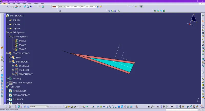
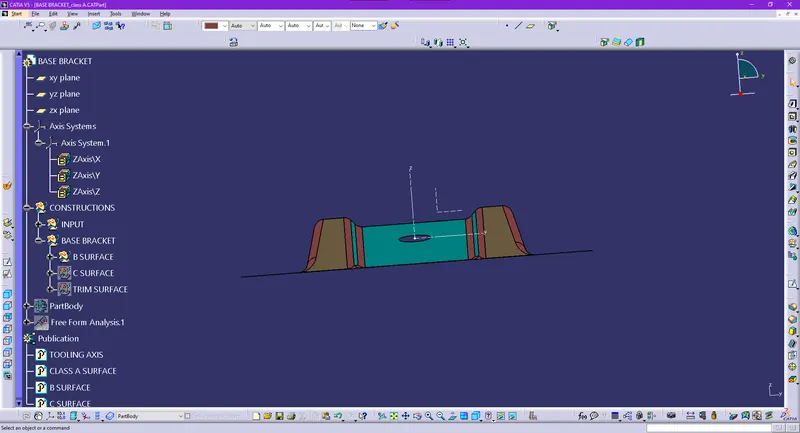
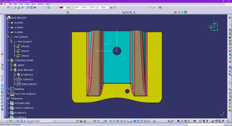
Of the three views,the third view has the maximum value of the projected area (largest area in yellow colour), hence we can conclude that tooling direction can tentatively be almost perpendicular to this plane
For reference purpose, we create a dummy tooling axis in the z direction
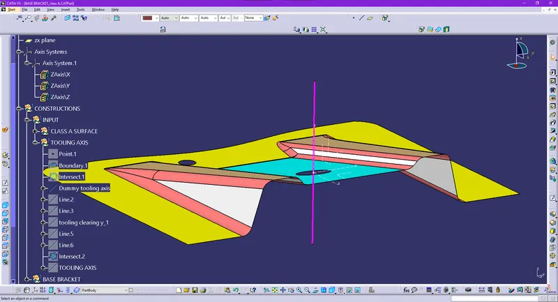
This enables us to analyze the 4 walls marked below to find out the tooling direction
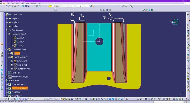
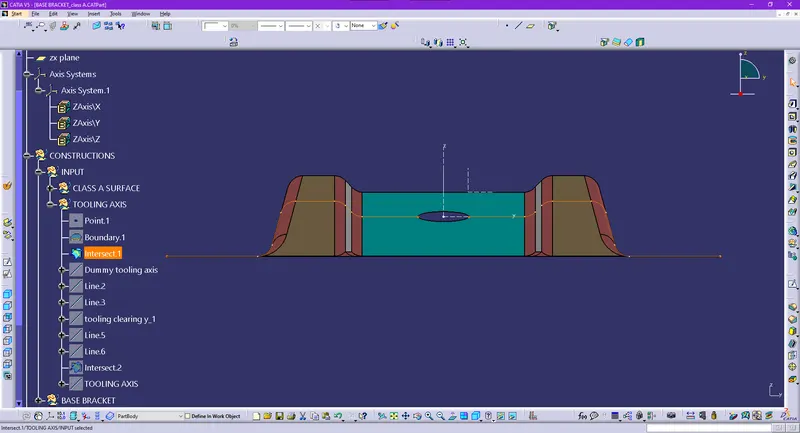
Using the intersects along the [zx] plane and bisecting the wall intersections will give us our tooling direction
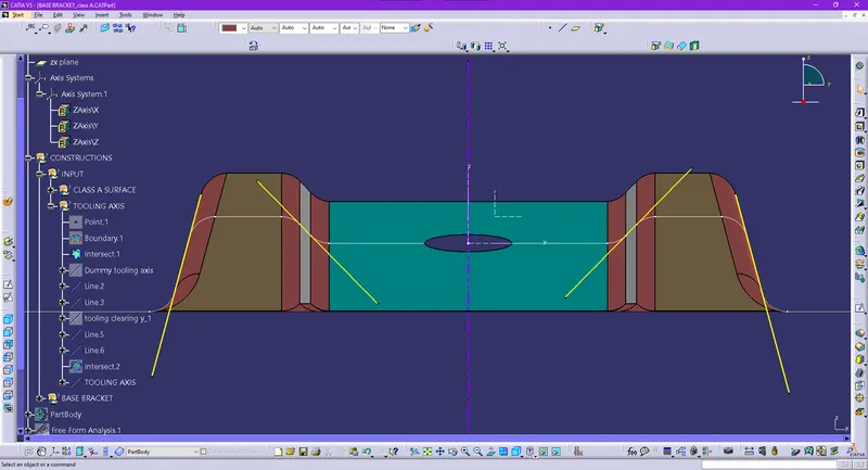
Here, the tooling axis is highlighted in purple and the wall intersection extensions in yellow.
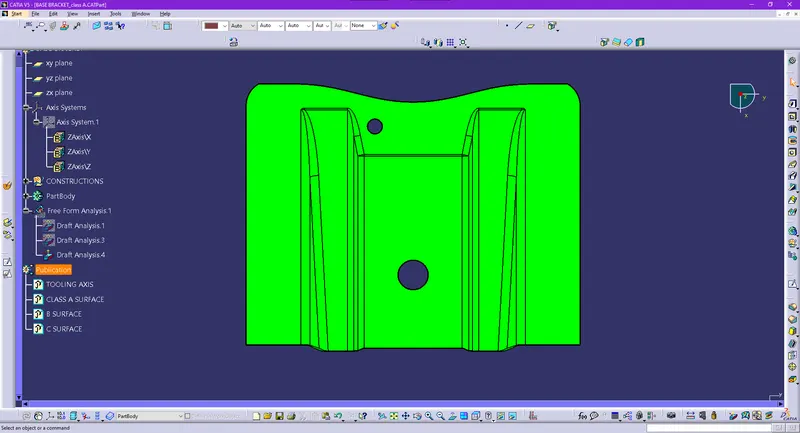
Now to check whether this tooling axis clears the surface for a minimum draft angle of 3 degrees, a feature draft analysis with respect to this new line for the given class A surface is conducted with that minimum drafting angle
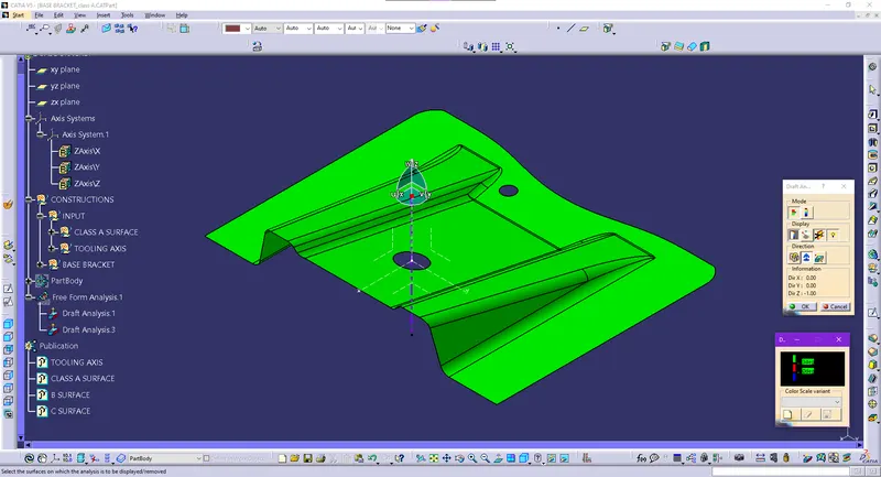
The output in green means that the class A surface is clearing the tooling axis with the given draft angle hence, the tooling axis can be used for Class C surface creation.
1b_Draft analysis of the final plastic component:
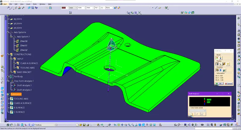
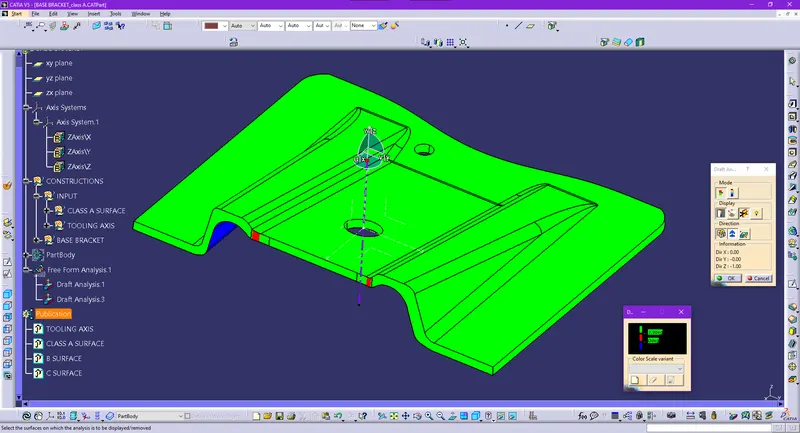
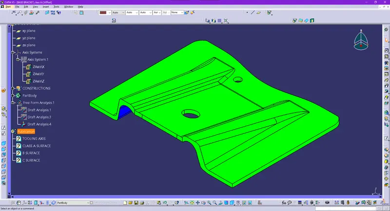
The draft analysis above is conducted for a minimum draft angle of 2.7 degrees. This can be attributed to the computation methods employes within the software capabilities wherein although a sweep was created with draft direction reference for a minimum of 3 degree angle, some surfaces produced went below 3 but not lower than 2.7 degrees.
This is the draft analysis output for 2.9 degrees (the red areas have a minimum clearence of 2.7 degrees)
2
ISOMETRIC
FRONT
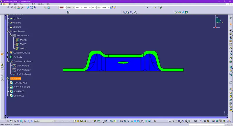
SIDE
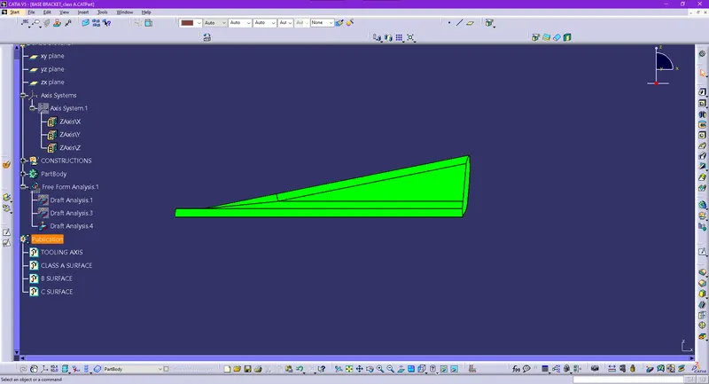
TOP