Week 12 Challenge
AIM
Is to create a proper ejection system with ejector pins and plates, runner and gate system, air vents and cooling channels for the mold.
PROCEDURE FOR EJECTOR SYSTEM
- For creating Ejector Pin first create a Plane using Reference Geomentry option and use circle profile to create circles and cut it using Extruded Cut option.
- Using the same circle sketch and use Extruded Boss/Base option to extrude the circle for creating Ejector Pins.
- For Relief create a circle using circle profile option and cut it using Cut Extruded option.
- For creating a D-Pin Head create a circle and line sketch using circle profile and line and Use Trim option to remove some areas and extrude using Extruded Boss/Base option.
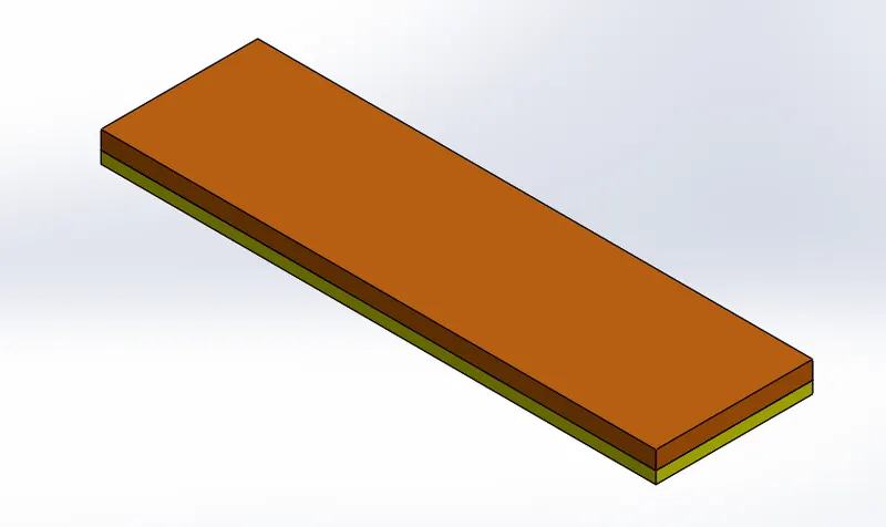
- For creating Ejector Plate create a rectangle sketch using rectangle profile option and extrude using Extruded Boss/Base option.
- For creating Ejector Back Plate create a rectangle sketch using rectangle profile option and extrude using Extruded Boss/Base option.
IMAGE OF EJECTOR PIN
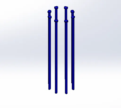
IMAGE OF EJECTOR PLATE AND BACK PLATE
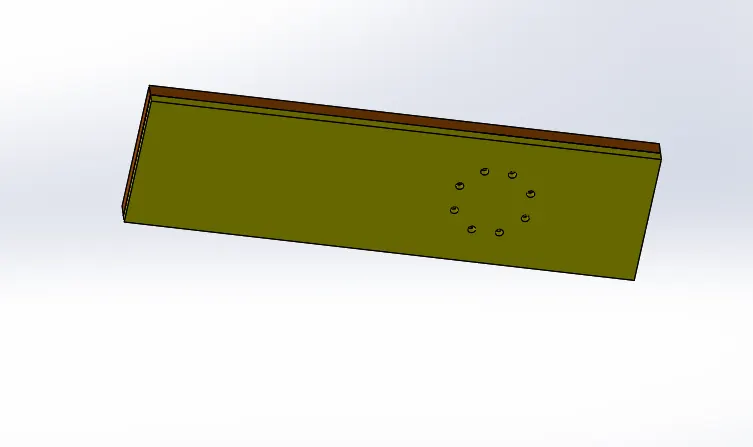
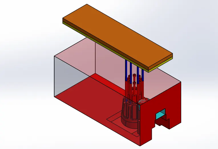
OVERALL DESIGN
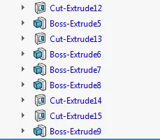
FEATURE TREE FOR EJECTION SYSTEM
PROCEDURE FOR RUNNER AND GATE
- First create a circle using circle profile option and cut it using Cut Extruded option.
- Again create a circle using circle profile option and cut it using Cut Extruded option and give some draft.
- In core near the spure create a circle using circle profile option and cut it using Cut Extruded option.
- For creating a Runner create a line sketch and extrude using Extruded Boss/Base option and in that use thickness option and give draft by using Draft option and give some fillets using Fillet option.
- For creating a Gate create a line sketch and extrude using Extruded Boss/Base option and give draft by using Draft option give some fillets using Fillet option.
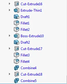
- Finally join the Runner and Gate using Combine option in that use add option and Sub it using Combine option.
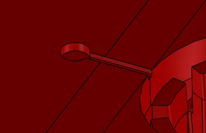
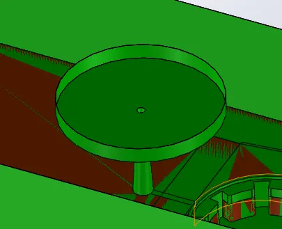
IMAGE OF SPURE, RUNNER AND GATE
FEATURE TREE
PROCEDURE FOR AIR VENT
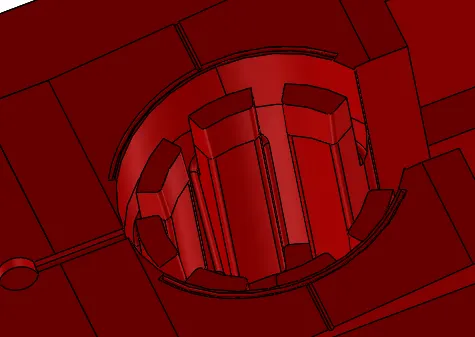
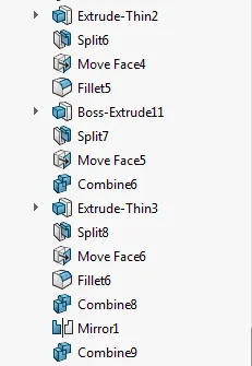
- Create a circle sketch using Offset Entities and extrude using Extruded Boss/Base option after that use Split option.
- Use Move option to extend the body and give some fillets to the edges using Fillet option.
- Do the same process of another offset sketch and join it using Combine option
- After that create a line sketch at the end of the body and do the same process as pevious done.
- And add the two bodies using Combine option.
- For other side use Mirror option and Sub it using Combine option.
IMAGE OF AIR VENT
FEATURE TREE
PROCEDURE FOR COOLING CHANNEL
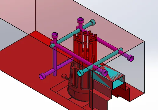
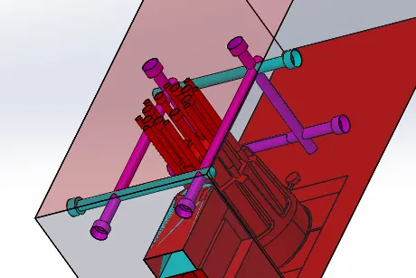
- For creating Cooling Channels use Hole Wizard option as per the given data in the front plane
- Do the same process for the right plane and top plane.
IMAGES OF COOLING CHANNEL
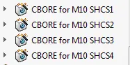
FEATURE TREE
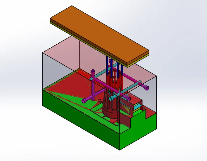
FINAL MOLD DESIGN
FEATURE TREE