Week 11 - Project - A pillar Design with Master Section
Project - A pillar Design with Master Section.
Part Tree.
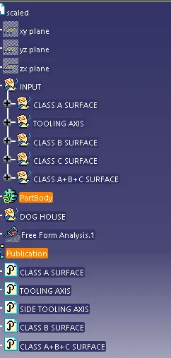
Tooling Axis.
Tooling axis is the direction in which a core or cavity of mold opens. This Axis is very important to determine the orientation of the component in mold, core and cavity design as well as to run the draft analysis of the component.
Side Core Axis.
Class B Surface.
The thickness of the component as 2.5mm. Now we need to create a B surface which will be similar to the A surface at an offset value of 2.5mm. there are some discontinuities happened while offsetting the CLASS A surface so I repaired it to form a closed boundary by using the multiple extract, extrapolate, trim and fill surface commands and tools.
Class C Surface.
C surface is created with help of A-Surface by using the Sweep(with reference surface) and Boundary command separately, finally joined together to get the final C surface.
Joining of Class A & C surface.
Joined the class A & C surface together with join command. after that small gap formed, solved that changing the join deviation from 0.001mm to 0.003mm.
Joining Class B with (A+C) Surface.
after that I trim out the joined A and C surface to class B surface to get the final object.
Final Plastic.
Dog House.
Dog house is an engineering feature used in plastic design. Dog houses are used as support feature. Sometimes other engineering features like snaps, locators, screw bosses are mounted on them to increase their strength.
Dog houses are subjected to draft analysis to prevent breakage of the component during ejection from the mould cavity. Dog house and other engineering components are built on the B-surface
- Dog houses are designed to avoid SINK MARK created on the CLASS-A surface by screw bosses and to solve the length issues when giving screw bosses which need to be assembled to other components.
- It is also useful when perpendicular screw bosses are required on the part to the tooling direction.
- Make a rectangle to enclose the screw boss in it but make sure it is open from one side.
- Sweep it with tooling axis as the pulling direction inwards.
- Close the top face by using multi section surface.
- Thicken it by 2.5 mm to the outward direction.
Ribs.
Upper Cutout.
Final Doghouse.
Final Solid.
Isometric View.
Front View.
Side View.
Top View.
DRAFT ANALYSIS.
- The part created has to be changed to material mode in display frame.
- Compass is enabled and align it along with the tooling direction.
- Lock command is then classified and Draft angle is applied.
- Color codes are classified and Draft angle is applied.
- Running point analysis is used to display permissible draft angle.