Week 11 - Project - A pillar Design with Master Section
Aim A pillar design with master section.
Requirement
- Picture of the sketches with sketch solving status geometry.
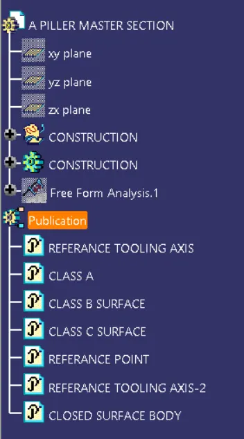
- Picture of the Detailed tree structure.
- Picture of the 3D CAD.
- Create closed body.
- Create a tooling axis and follow design rules.
- Follow the Master section to create a flange.
- Follow the master section for thickness and to create the Closed volume.
- Follow the master section to create Attachment features.
- The thickness of the Plastic to be 2.5 mm.
Tooling Axis
Its the direction at which the core and cavity opens is the tooling axis. Its predefined the feasibility of component very easily. for the tooling axis the following points to be consider
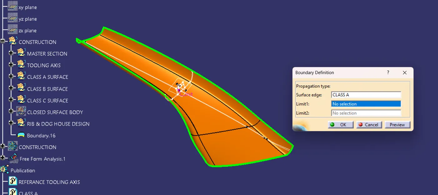
- First ensure the class-A surface is properly joined and has no discontinuity on it. For this we can use boundary command or join command.
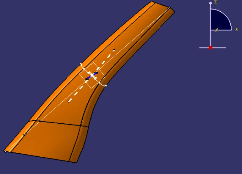
- Analyze the model manually or visually to see which direction is most suitable for tooling axis.
- As in 3D view we can see profile & flat surface, we can directly take the tooling axis perpendicular to that. But to be sure,let us analaze from all the views. The below images of the front side and top views shows the areas that we have to keep in mind while choosing tooling axis. As from X we cannot see complete profile so we cannot take axis along this. In Y we can see profile and flat surface so we can take tooling axis. In Z can not consider because the same profile and flat surface are not visible.
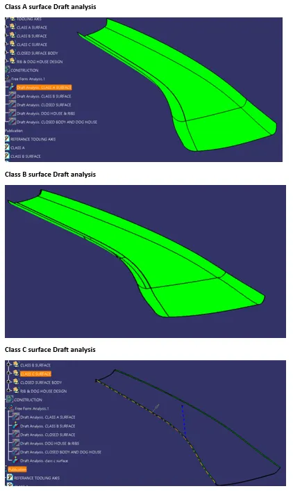
Class A surface
Its the primary surface which is given from styling team, to check surface is precise or free from patches for that check surface is joined properly via boundry command if any issues found get back to the styling team.
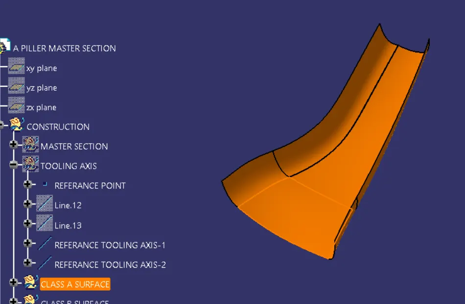
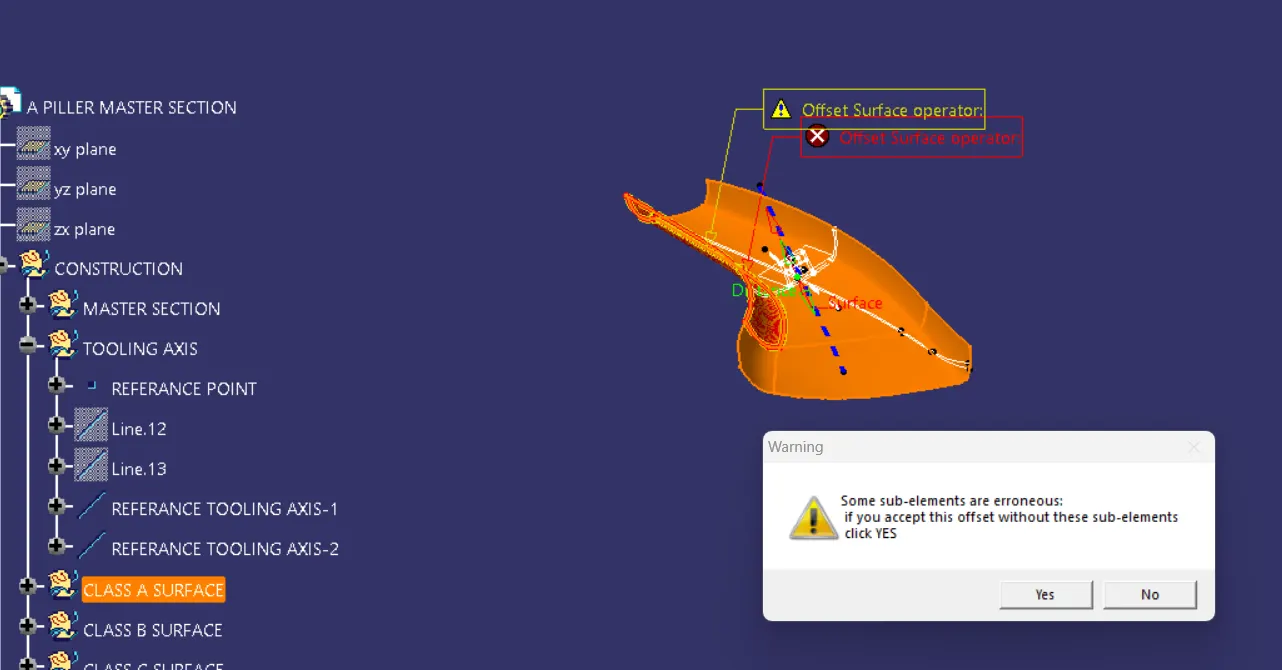
Example- Here we can found the same issue in A piller class A surface for creating class B surface we have to ensure about given thickness of the component is 2.5 mm but surface is not selected cpomplitely more refeance see the given below class A surface picture's.
Class B surface
Its the offset values of class A surface and its given 2.5 mm whay we are creating class b surface beacuse we have to create closed body using surface design.
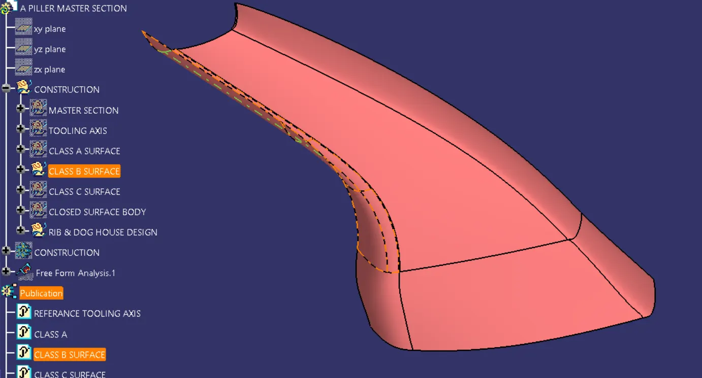
Class C surface
Its the outer edge boundry project along the way of tooling axis called c surface.
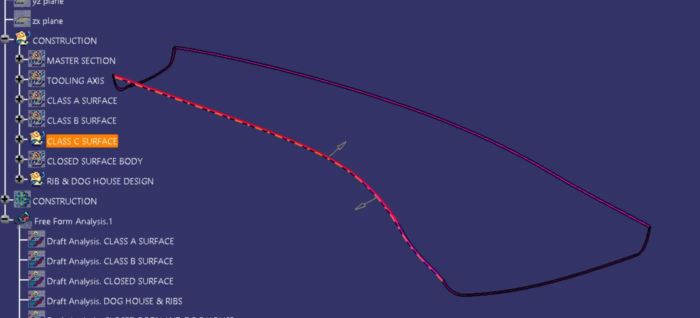
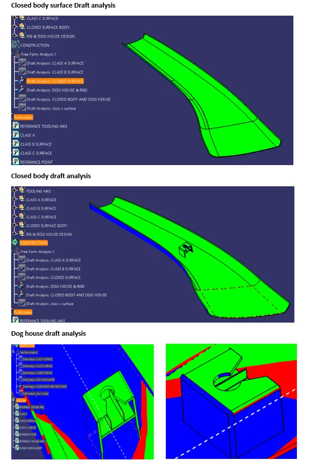
Closed body surface
When three surface class A, Class B & Class c surface are joined togetherly called c Surface body.
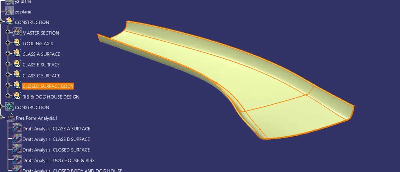
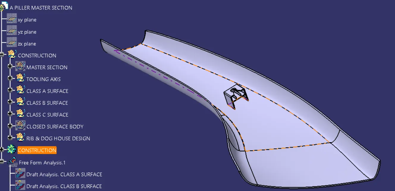
Draft Analysis
Draft:- The draft is the amount of taper molded or cast part perpendicular to the parting line draft angle are a design consideration that makes it much easier for a part to release cleanly from a mould A draft angle is calculated as a degree measurment (less often, ann inch or milimeter mesurment) from vertical axis or of a mould & it helps account of thermoplastic shrinkage. a partical reality of the injection moulding process for most materials.
Draft angles are generally a requirement of injection moulding design (though there are select few soft material, like nylon that can get away with angle of zero) The draft should be a part of the design manufacture and all stakeholders & contributors should be aware of its need at the out side of the design process. This includes product designers, design engineers etc & this allows considerations for desing requirement to be taken into account. Any draft is better then no draft.
Importance of draft
By accounting for thermoplastic shrinkage during the cooling process, draft angles significantly reduce friction between the finished, cooled part and the side of the mould, Not only does this create a much easier release process, but it also offers several other benefits, depending on the design of the part which is as follows:
Reduces the chance of damage to the part due to friction during the release.
Reduces wear and tear and chances of damage to the mould.
Ensures a uniform, smooth, unscratched finish when required.
Ensures the integrity and uniformity of other surface finishes and textures.
Reduces overall cooling time by lessening or eliminating the need for unconventional ejection setups.
Most, if not all, of these benefits, offer either direct or indirect overall production cost reductions.
Dog House Design
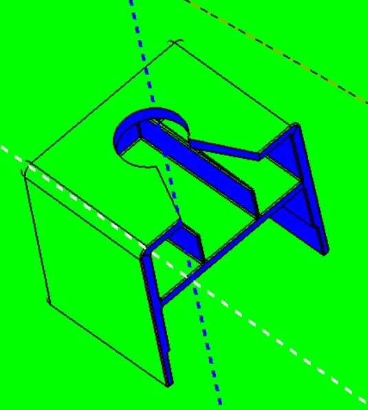
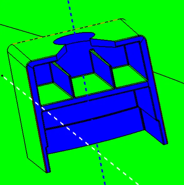
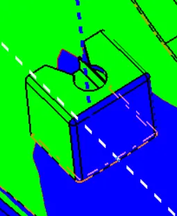
Dog house are designed to avoide sink mark created on a class A surface by screw vossed and to solve the length issues when giving screw bossed which need to be assembled to another components Its also useful when perpendicular screw bosses are required on the part to the tooling direction
C thickness should be 40% of the main wall thickness T.
Minimum width of the dog house is 12 mm.
Height of B should be 3 to 6 mm
Minimum Draft for the dog house 5 degrees to draw die.
- Procedure for creating Dog House Design
Minimum draft for the dog house 5 degrees to draw die.
To create dog house with reference of class A surface.
To create side core axis.
Side core axis-02 in normal to the tooling axis-01 so chosen tooling axis-01 for side core axis creation.
Create the dog house by creating a positioned sketch on the zx plane. using extrude or sweep method create outer walls.
Closed top wall by using multi section solid commed, offest by using class a surface but have to consider the given height.
Then se thicken command in the part workbench, to create dog house soild.
Give proper draft analysis by usign vertical & side axis.
Give draft analysis and fillets by considering the design rule.
Using boolean operation, union trim the dog house.
3D Part model in various orientations (Isometric, Front, Side, and Top View)
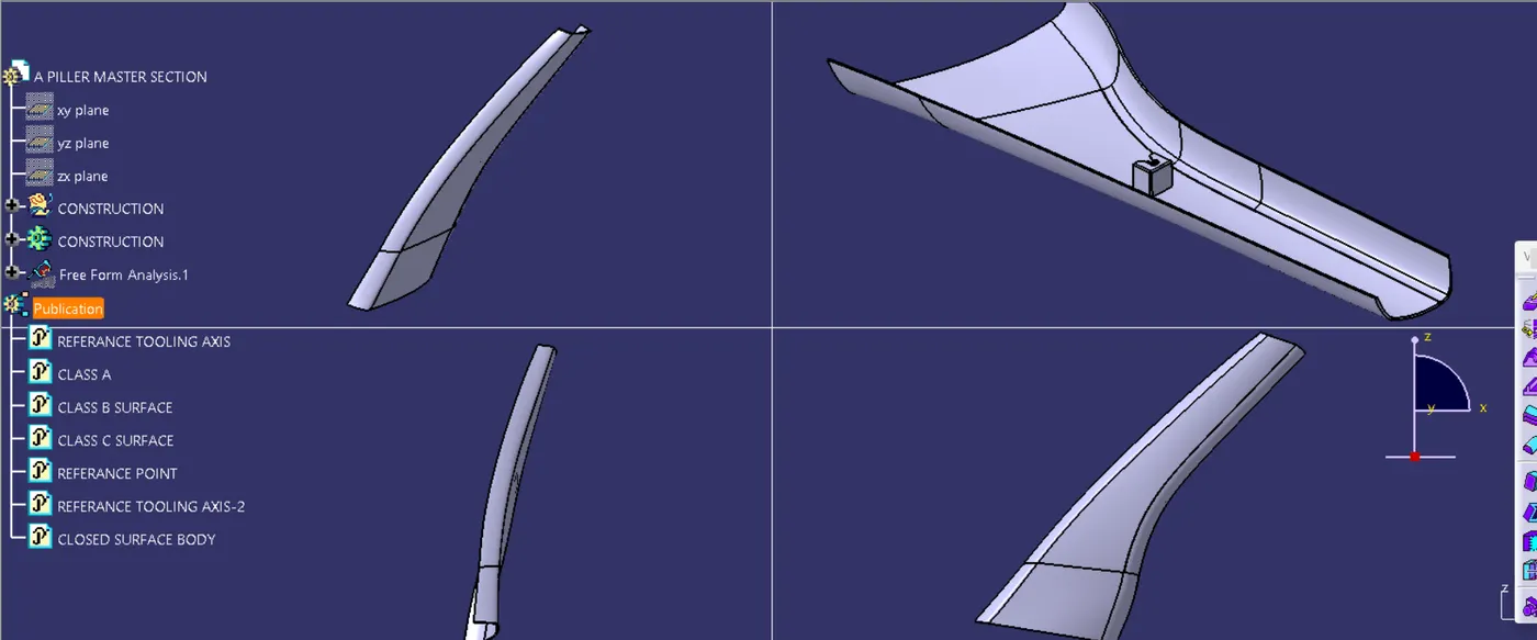

Tree diagram
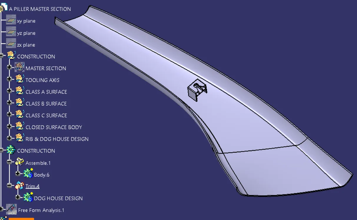
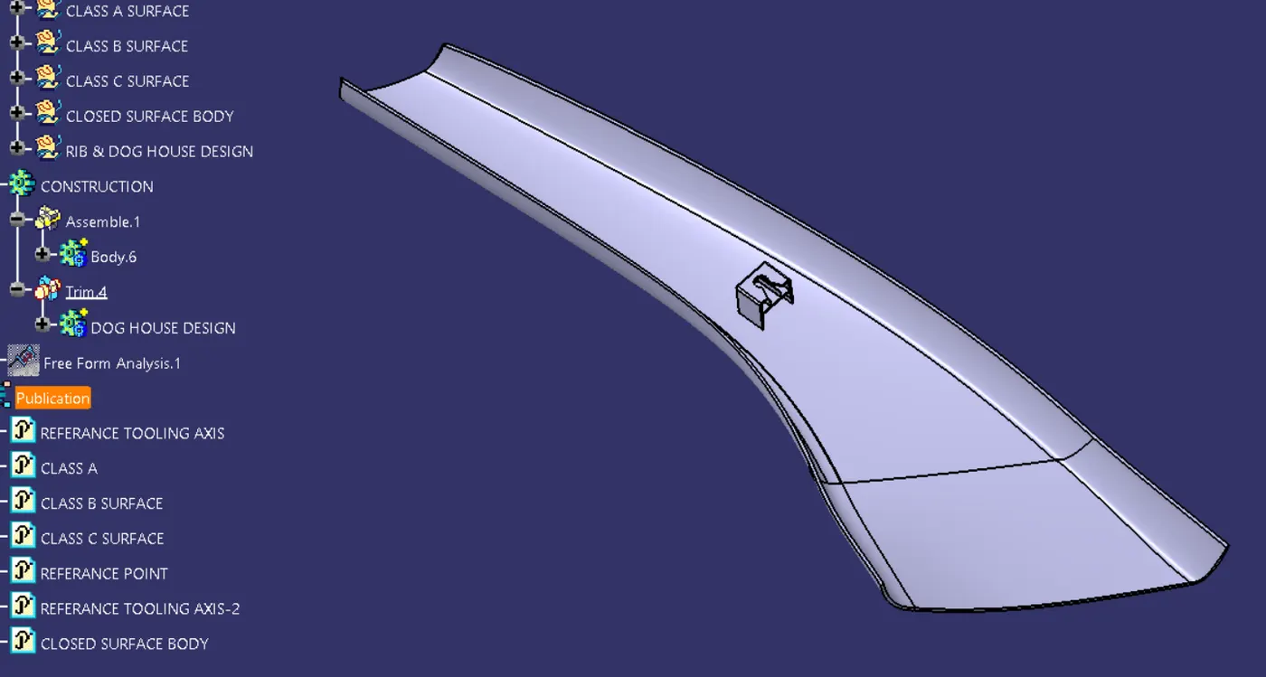
Conclusion In this way we have succussfully complited the A piller challenge.