Week 11 - Project - A pillar Design with Master Section
A-PILLAR DESIGN USING A MASTER SECTION AND DRAFT ANALYSIS
- OBJECTIVE:
- To do Draft analysis and Design A-Pillar with the engineering features with the help of the master section, Class-A, Class-B, Class-C, and Tooling axis.
- TOOLING AXIS
- Firstly, we have to create a tooling axis which is essential for designing the component and also for draft analysis.
- To create the tooling axis, I'm choosing bisecting method.
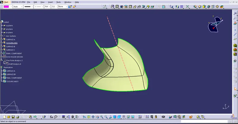
- With the help of the direct method, I had to create a tooling axis that probably clears all the surface of class A.
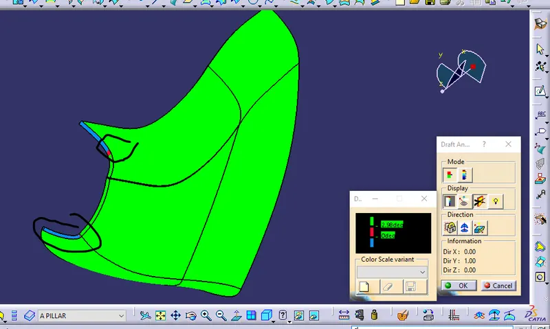
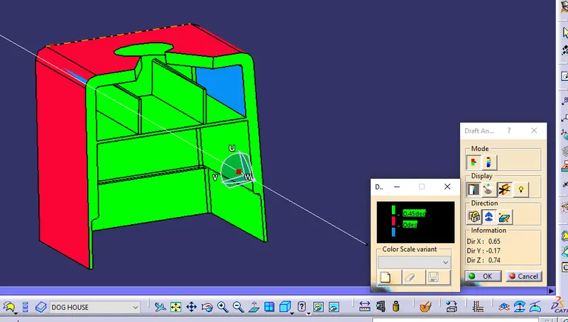
- Now, let's check the draft analysis of class A and the component Door Trim with dog house (refer to the below-given pic).
- DRAFT ANALYSIS OF CLASS A SURFACE:
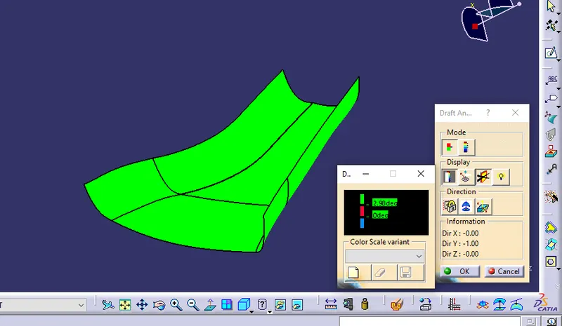
- Results: At 2.98 draft angle, the Class A surface clears well. (Refer to the below-given pic).
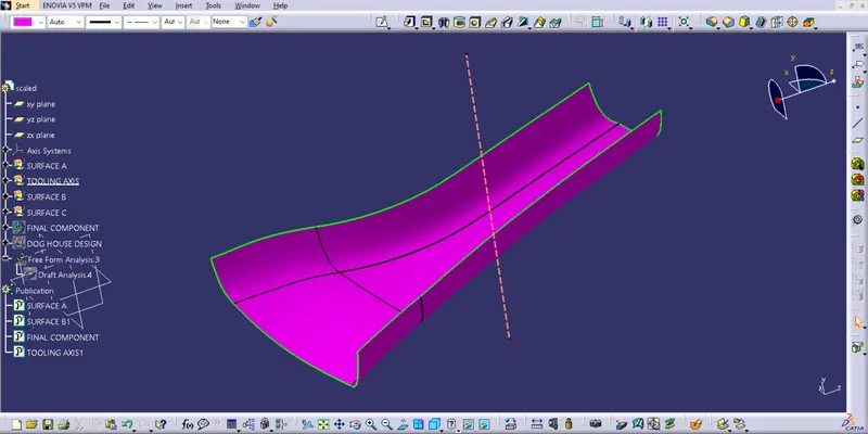
CLASS B SURFACE CREATIATION :-
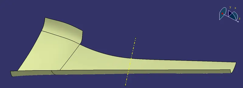
To create the class B surface initially, I measured the thickness of the master section (2.5mm). I offset the class A surface 2.5mm to the inside direction. The styling fillets on the class A surface are not offset properly, it created the patch on the offset surface. I used the sweep command to close the patch on the offset surface.
Offset patch:
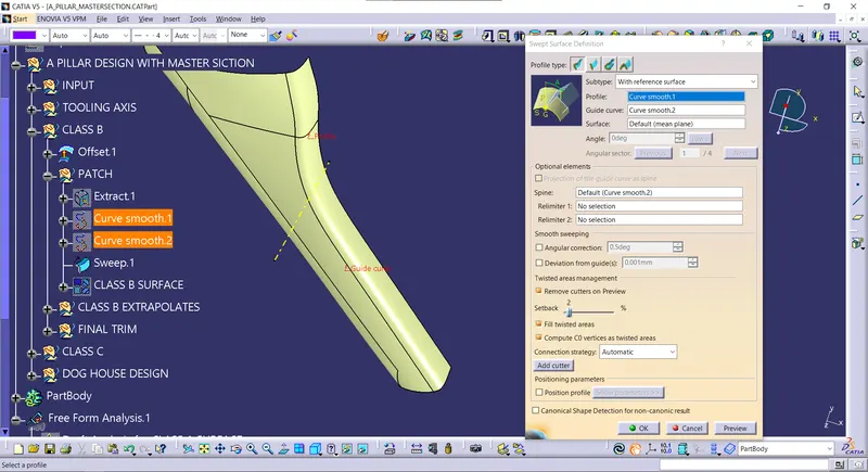
I extracted the edges of the patches, to give as a sweep command's guide curves to close the patch.
Class B surface:
CLASS C SURFACE CREATIATION :-
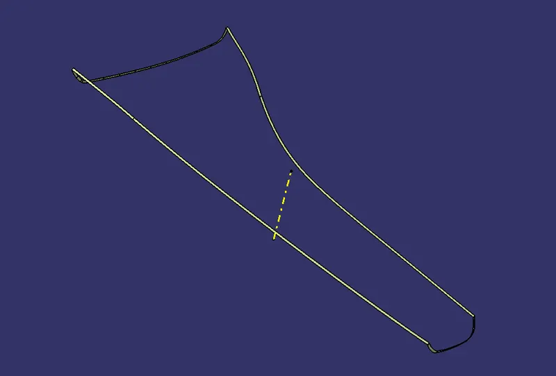
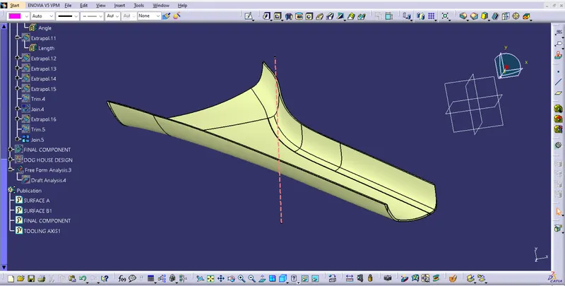
To order to create the class C surface, I used the sweep command. I sweep the class A surface edges along with referencing the surface for 4mm inside with 90deg. After the creation of the class C surface, the surface edges are needed to be extrapolated to intersect properly from all 4 sides. I trim the surfaces which extrapolated, to get the closed class C surface. I joined the class A surface and Class C surface to get a single surface of class A+C surfaces. I trim the Class B surface with class A+C surface join, to get the closed surface to create the solid body.
class C surface:
CLASS A+C JOINT ( FINAL SURFACE):-
Solid part body creation:
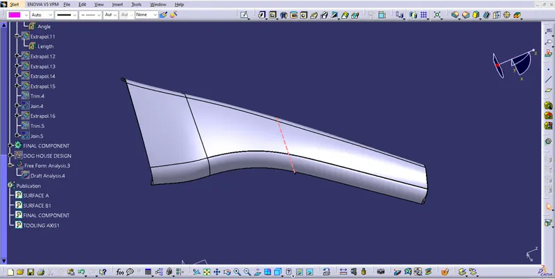
To create the solid part body, I used closed surface command in the part-workbench. I gave the closed surface as an input in the closed surface command.
solid body:
DOG HOUSE DESIGN :-
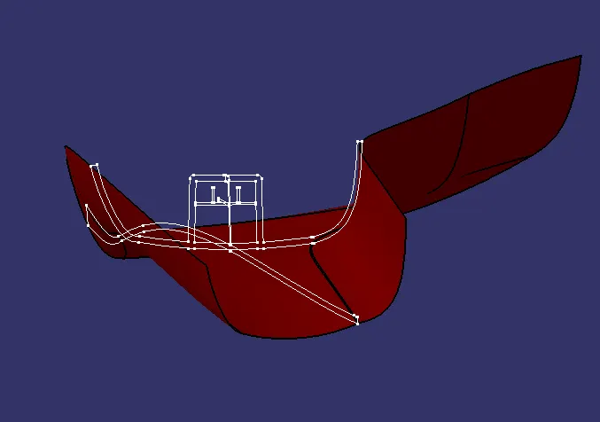
- To create the dog house on the B-side, I extracted the lines on the master section and I create a plane to extract the lines concerning the master section.
- I extracted the faces which are required to create the shell for the dog house, and I trim the surfaces with each other as per the master section dimensions.
Dog house outer shell:
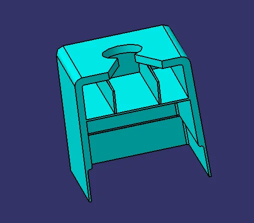
- Referring to the given master and designing the Dog house.
-
Create the Dog House for the Door Trim considering the design rules mentioned in the video.
-
Consider the thickness of the part to be 2.5 mm.
"C" is where the doghouse contacts the backside of the surface.
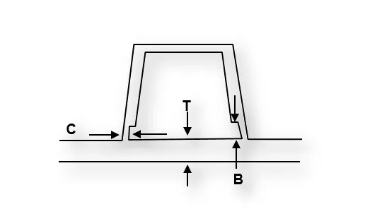
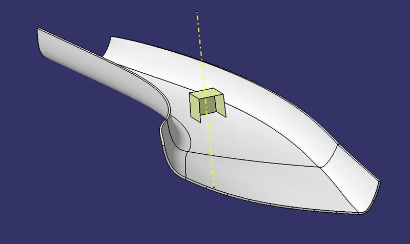
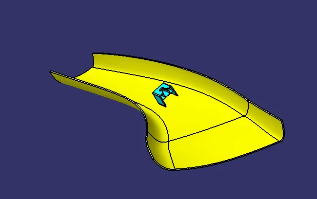
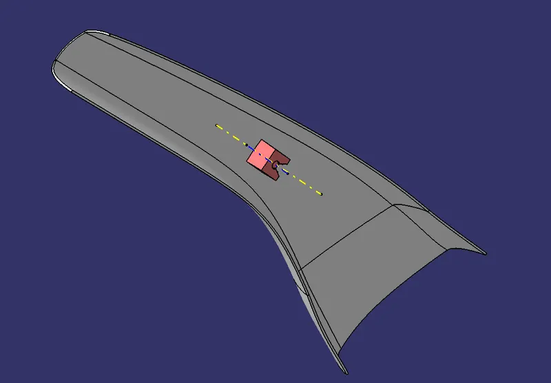
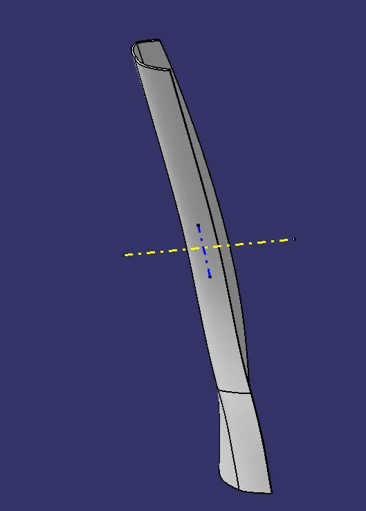
- I created the side core access, by creating a line at the centre of the back surface by creating the point.
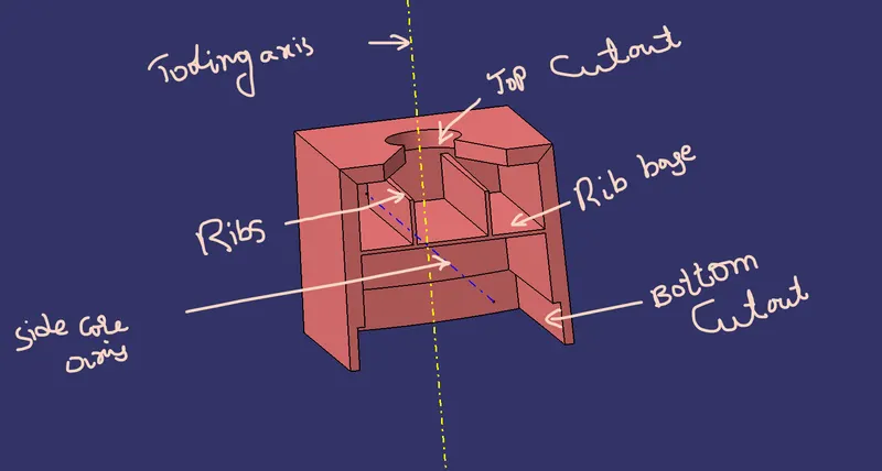
- I thicken the shell for mm to inside. After thickening the surface, I gave deg draft to inner surfaces of the dog house.
- Now we need to give the bottom cutout for the dog house. To give the bottom cutout, I extracted the surface and offset it to 1mm outside (the bottom cutout should be 40% of the thickness of the dog house). I extract the upper surface of the dog house and offset it to 17mm bottom direction, to trim with the offset of the inner surface.
- After trimming the bottom cutout surface, I split the surface from the solid shell of the dog house. I gave a 0.5deg draft angle to the bottom area concerning to the side core axis.
- I created the rib base and ribs concerning the master section dimensions, and I gave a 0.5deg draft angle to the rib base and ribs. After drafting the rib base, I added the rib base and ribs to the dog house shell to make a single body.
- I created a sketch for the top cutout on the dog house, and I pad the sketch to the downside and removed it from the dog house part body.
Dog house top cutout sketch:
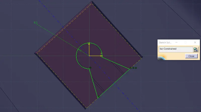
DOG HOUSE DESIGN :-
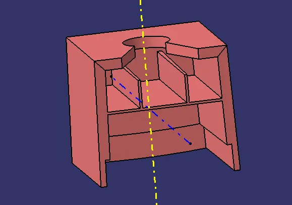
- I added the dog house to the main part body of A pillar solid.
Solid part body of A pillar with Dog house:
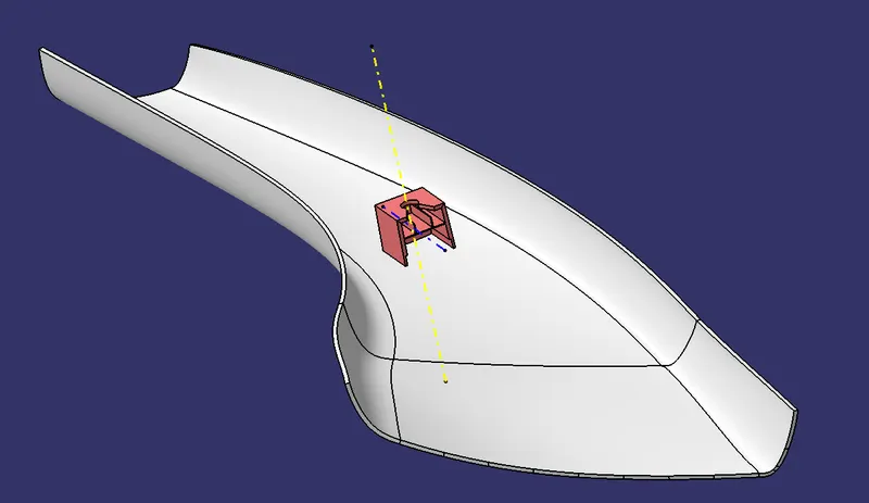
Draft analysis for the solid part body:
The draft analysis is used to check the surface draft angel and to know whether all the surfaces are drafted properly or not.
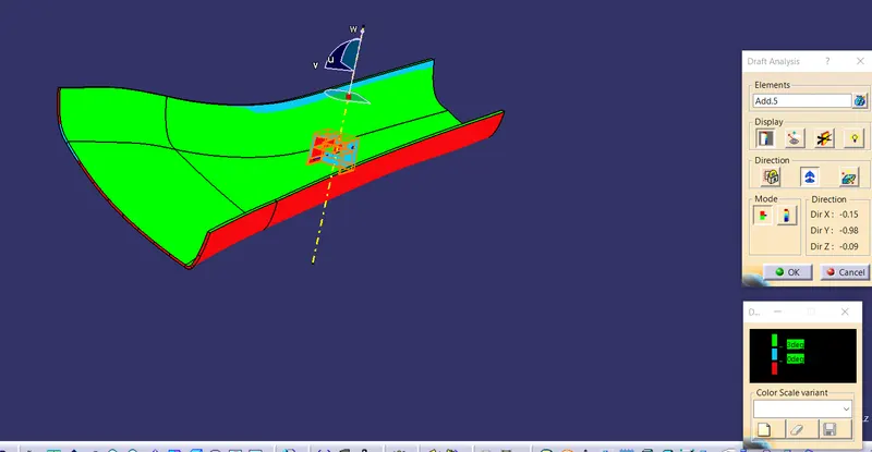
- The draft angle for the solid body of A pillar is 3deg, some surfaces are not cleared properly with a 3deg draft angle. Previously I mentioned in the class A draft analysis report with a 1.9deg draft angle all the surfaces are cleared properly.
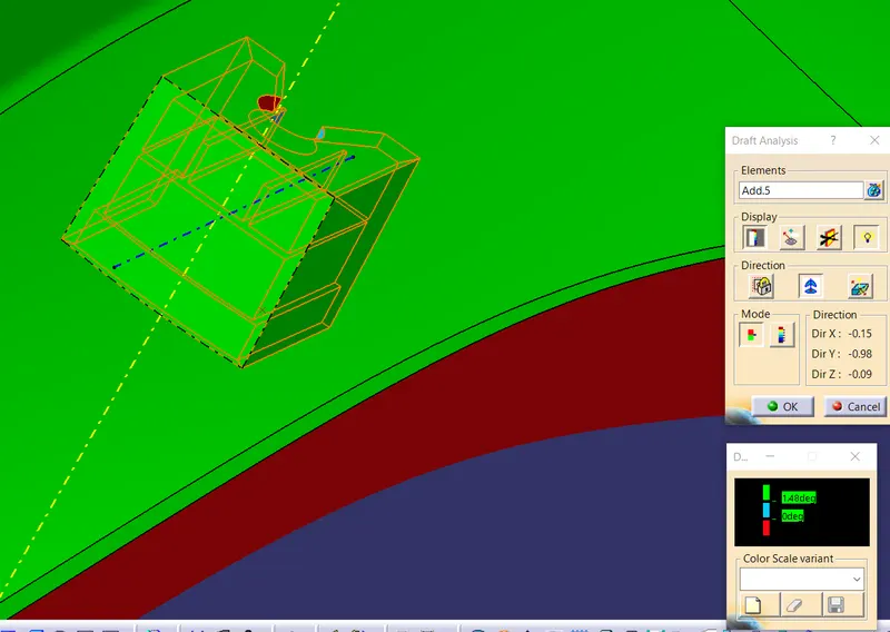
- The draft angle for the outer surface of the dog house is 1.5deg.
- The draft angle for the inner surface of the dog house is 0.5deg.
Draft analysis for A-pillar:
3deg draft angle:
1.9deg draft angle:
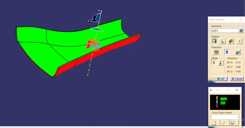
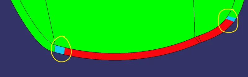
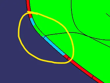
- Because of class A surface curvatures and deviations, some areas on the class C surface are not highlighted in green colour.
The below-given surfaces are not cleared properly:
Draft analysis for dog house outer surface:
4. Final Operation to get A-Pillar:
- Firstly, Select the join operation and join the class A and class C surfaces.
- Trim those joined with the class B surface.
- After that, I got the final A-Pillar.
- As the surface is hollow from the inside, for this go to the part workbench and select the close surface.
- After that analyze the output surface with draft analysis.
- So, in this way, we got our final design as A-Pillar (Referring to the pic below).
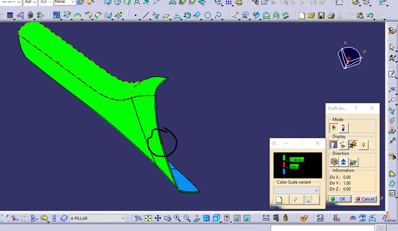
- DRAFT ANALYSIS OF A-Pillar:
- Results: At 2.98 draft angle the surface of the A-pillar cleared well but some portions were not cleared. (Refer to the given pic below).
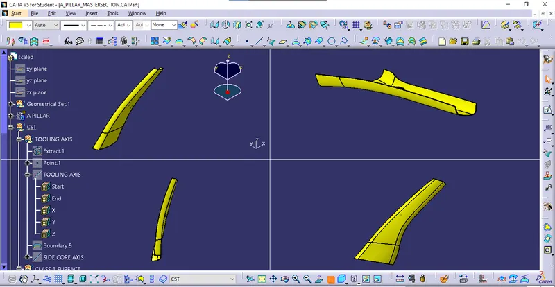
Different views:
Isometric view:
Front view:
Back view:
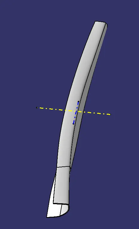
left side view:
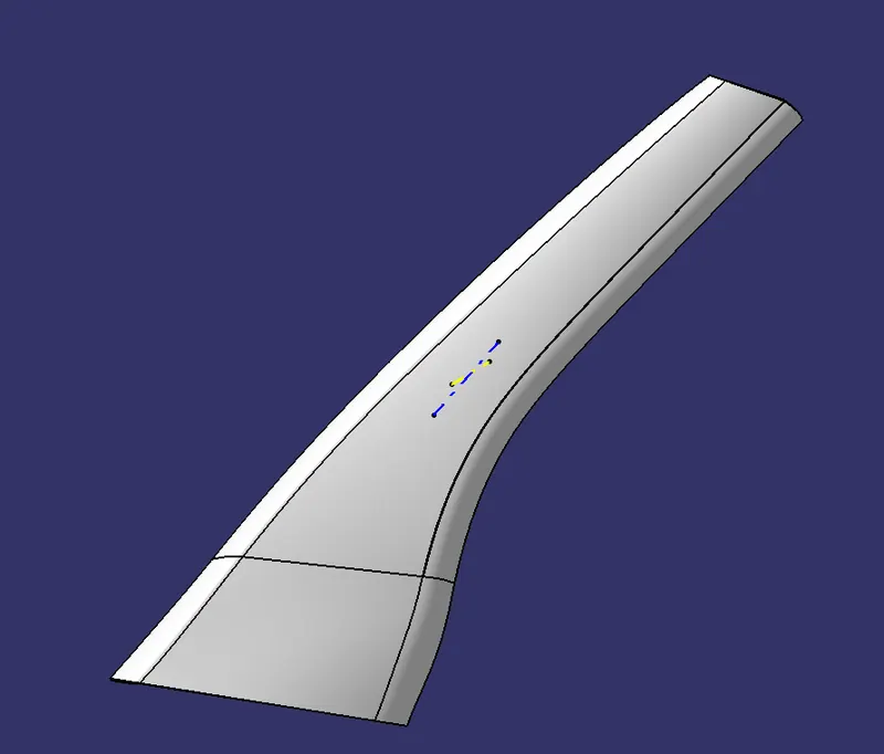
Right side view:
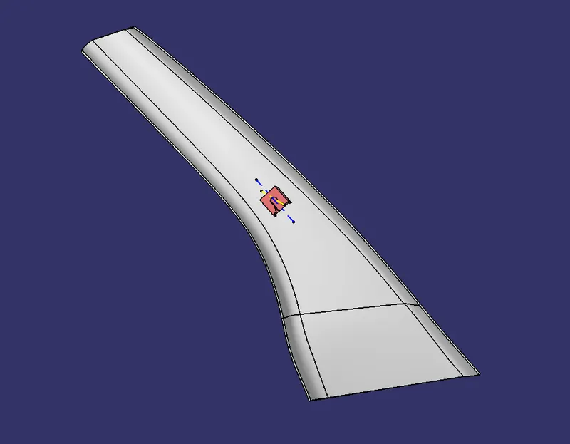
Top view:
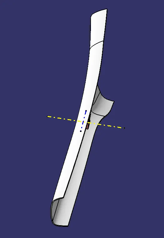
Bottom view:
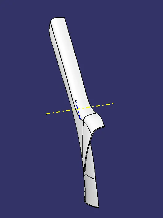
Tree Structure:
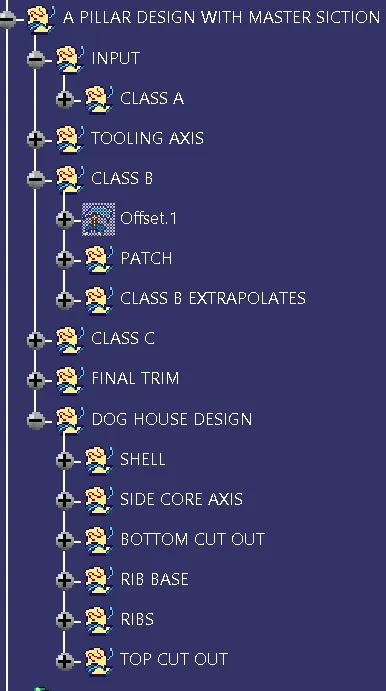
Geometrical sets:
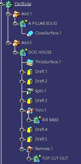
Part Body:
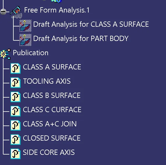
Free Form Analysis (Draft analysis) & Publications:
Leave a comment