Week 11 - Project - A pillar Design with Master Section
Week 11 - Project - A pillar Design with Master Section
AIM:
To create the A Pillar Design with the master section given as the intersection sketch with the Class A surface and create the tooling axis and perform the Draft analysis for the final solid part.
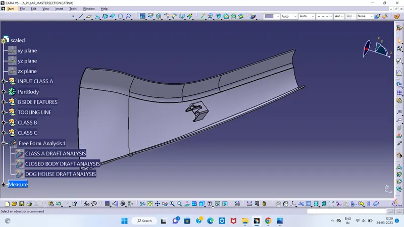
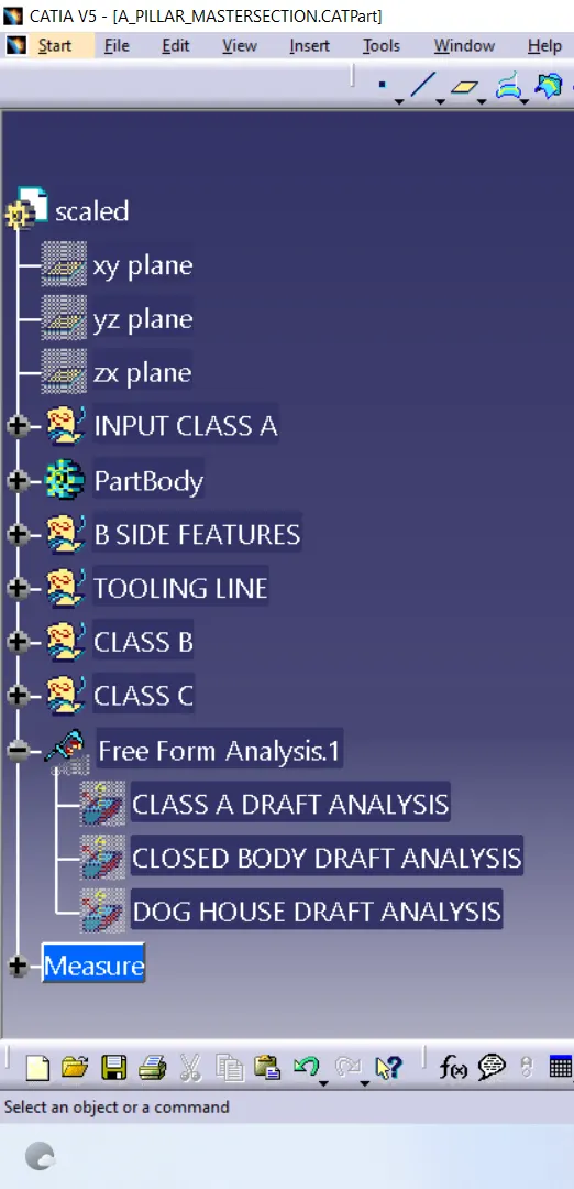
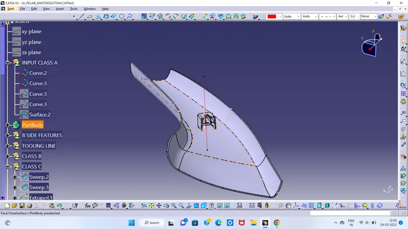
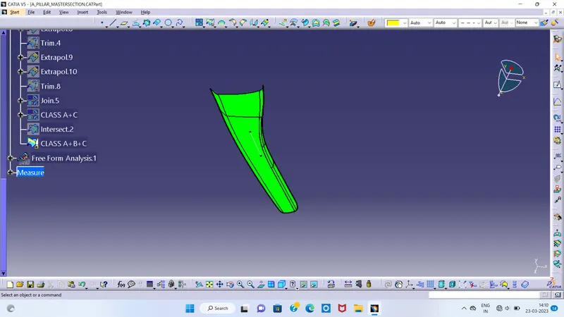
MY DRAWING TREE STRUCTURE
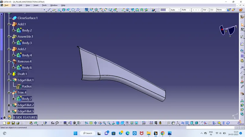
A PILLER IMAGE
Objective :
- Create the required Tooling axis by using master section and bisecting methode.
- Design the Class-B and Class-C surfaces and close all three surfaces.
- Design the Dog house and its internal parts as given Drafts and mater section sketch.
- Draft analysis for the final solid part and side core Draft analysis.
MASTER SECTION:
Master sections development takes place during feasibility check and concept validation stages of the product life cycle. These are typically the guides for design requirements and which decides the component packaging after the development of the concept design, i.e class A surfaces.
Master section helps us to decide the feasibility of the concept design, the clearances, the packaging and the fixation strategy of a component before converting the concept design into a solid 3D engineering design.
During the period of vehicle concept design the evaluation of the master section performance depends mainly on the reference vehicle data and experience of structure design engineer.
CLASS A SURFACE:
It is surface which is made by the designer. It is aesthetic surface and usable outside futures are on this surface.
CLASS B SURFACE:
It is bottom side surface of class A surface. It is made by class A surface. It is formed with thickness distance from class A surface.
CLASS C SURFACE:
It joins the both class A and class B surfaces. This surface is equal to the thickness of the component.
Theory :
Tooling Axis :
Class-A surface is first analyzed to create the tooling axis or tooling direction that molds pull apart in injection molding. Tooling direction is important for plastic product design as it decides direction for mold seperation.
Step followed for creation of tooling axis :
- Reference point is first created on extracted surface.
- New axis system is deployed to plot clearance lines.
- The X-direction and Y-direction along the class-A were used to create tooling axis.
- Graphic properties of tooling axis were change before publishing.
Draft Analysis :
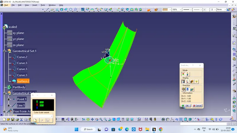
The Draft angle is the amount of taper for molded or cast parts perpendicular to the parting line. It can be measured in degrees. A functional part for injection molding has to have Drafts facing both cavity and core sides to reduce the risk of damage to the parts and ensure ejection. And also important is to overcome the vaccume forces by letting air in between the metal to the plastic for the part to relaese properly. Adding maintaining a decent cosmetic finish.
Nominal values for Draft angle :
- 3 Degrees is the nominal Draft angle.
- 7 Degrees for textured surface.
- At the minimum of 0.5 Degrees can be manufactured by special tools. But it will increase the manufacturing cost.
Draft analysis for Class-A surface :
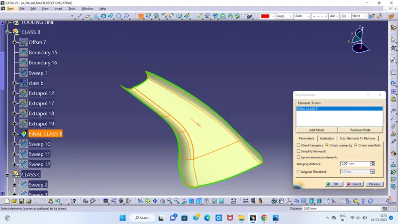
CLASS B SURFACE
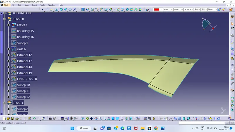
Create B surface offset form the class A surface as per master section.
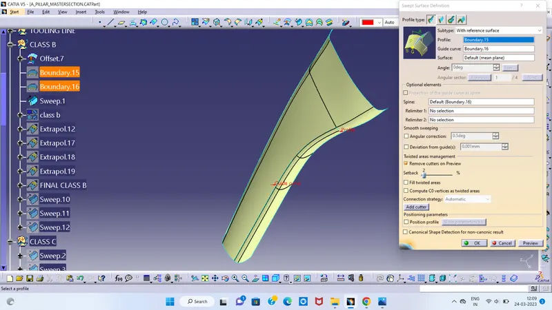
missing surfaces create with swept surface.
let's join the surfaces & create the class B surface.
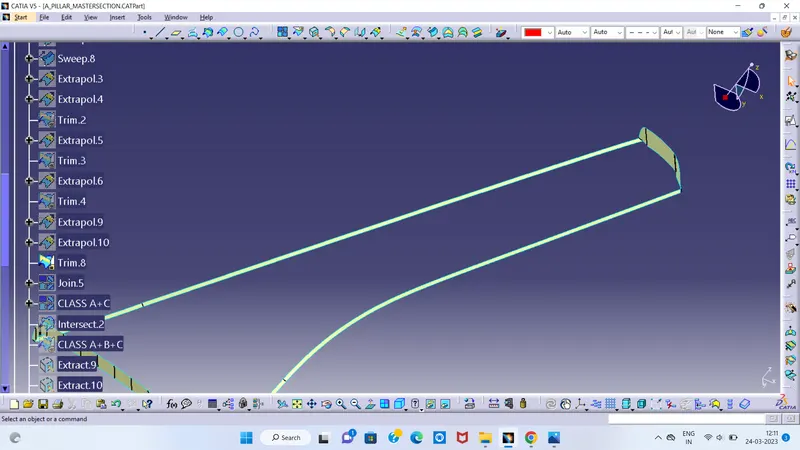
CLASS C SURFACE
create the surface with swept & multi section surfaces.
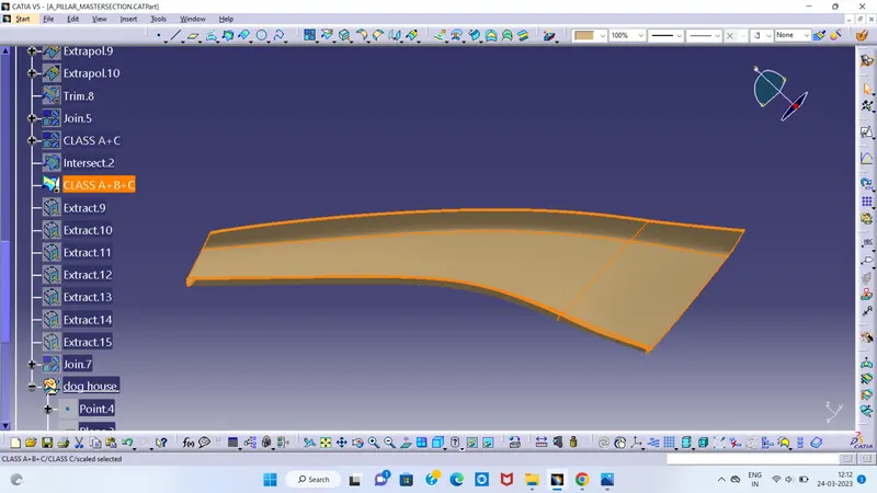
FINAL SURFACE
Join the surfaces without any boundary.
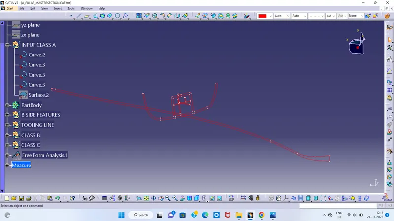
Given Master section Sketch 1 :
Given 3D view of Dog house :
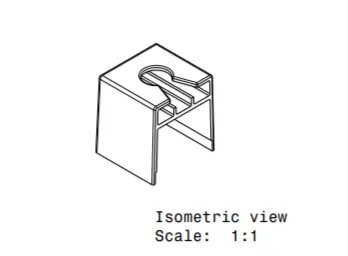
Creation of Dog House :
Sketch for Dog house :
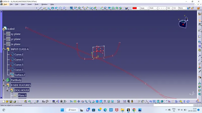
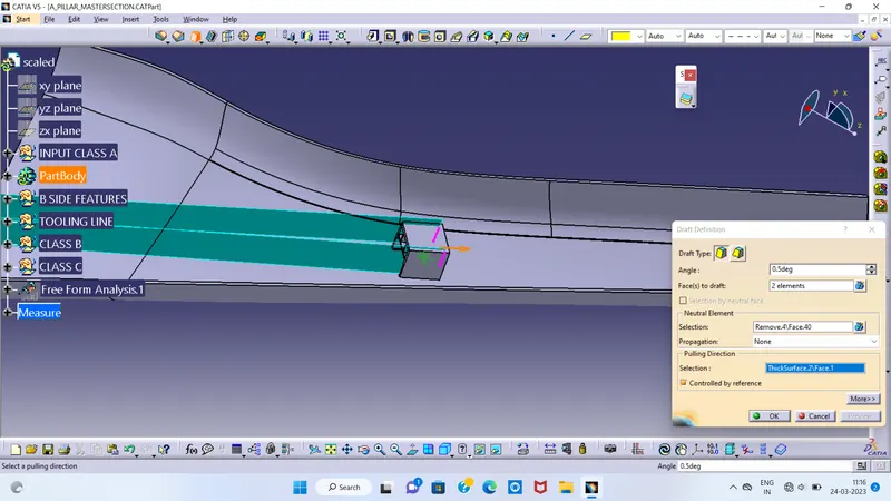
Sketch for Cutting Element :
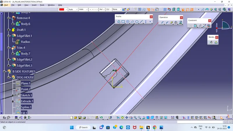
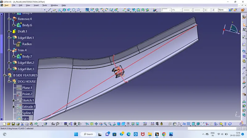
Final Dog house :
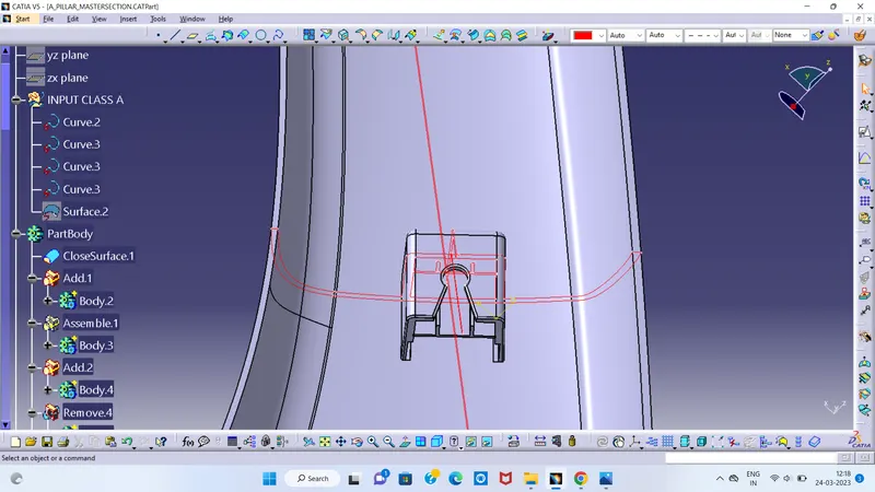
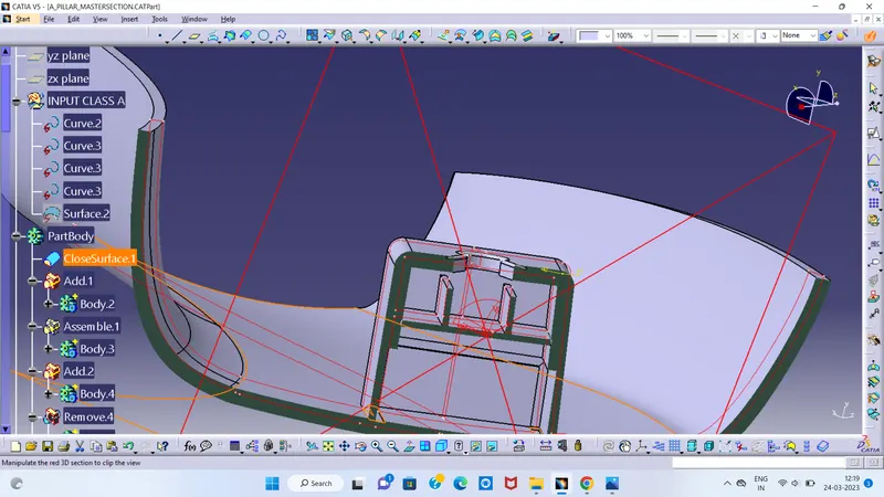
CHECKING FOR DRAFT ANALYSIS BOTH PARTS
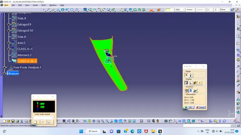
CHECKING DOG HOUSE DRAFT ANALYSIS
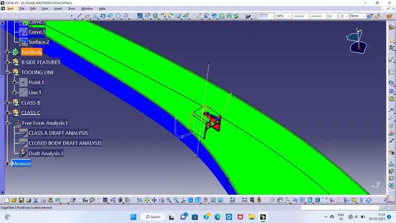
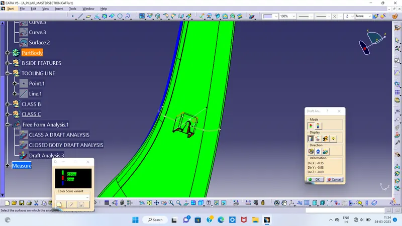
DIFFERENT VIEWS