Week 11 - Project - A pillar Design with Master Section
OBJECTIVE: To create the A-Pillar's Plastic component from the given Class A Surface using the Master Section that is provided while following all the design rules.
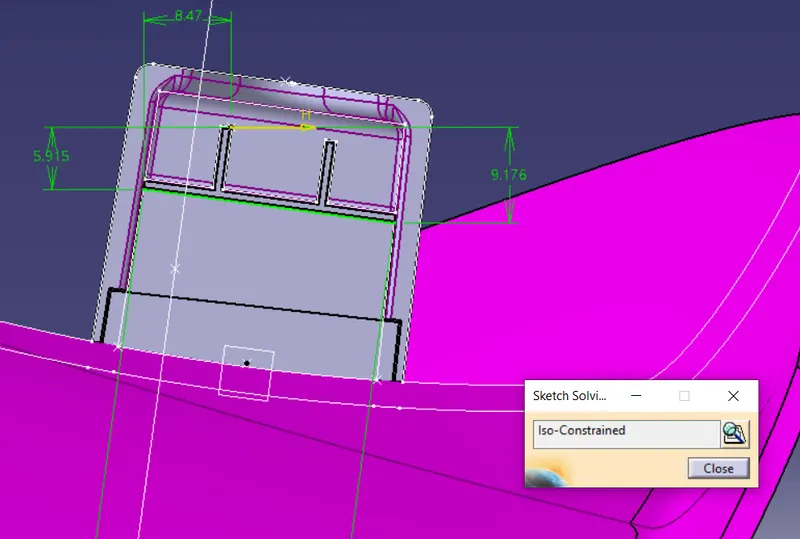
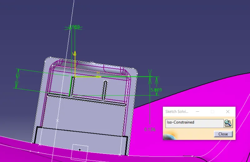
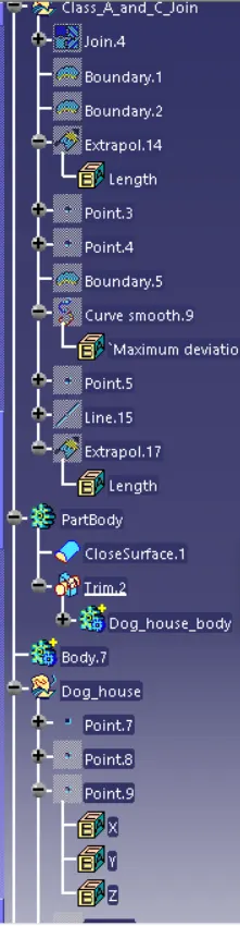
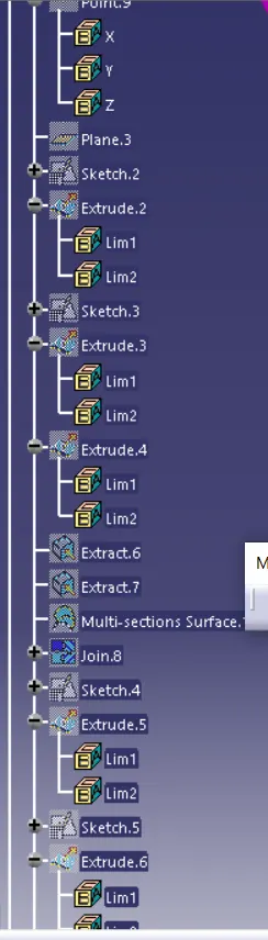
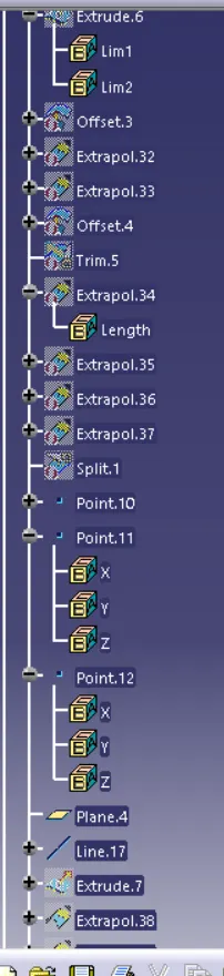
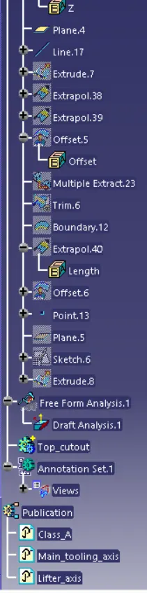
PROCEDURE TO CREATE THE MAIN TOOLING AXIS:
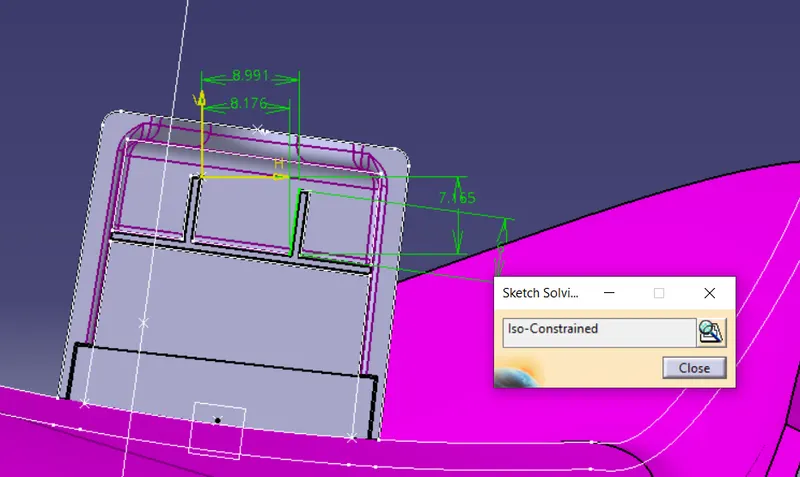
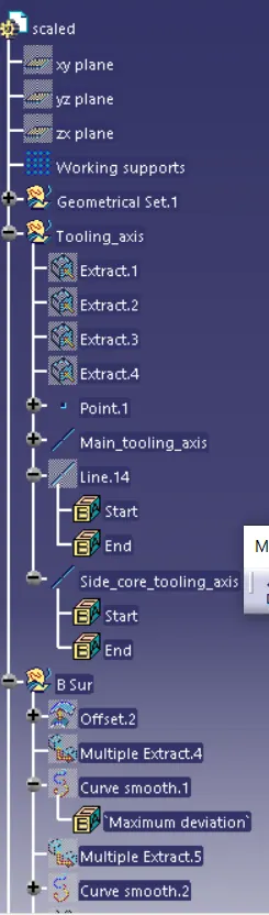
Since we have a Master Section provided to us using which we have to create the desired A-Pillar Plastic Component, We'll use that Master Section by extracting the lines as shown below and create a Bisecting Line with respect to those extracted lines to create our Main Tooling Axis.
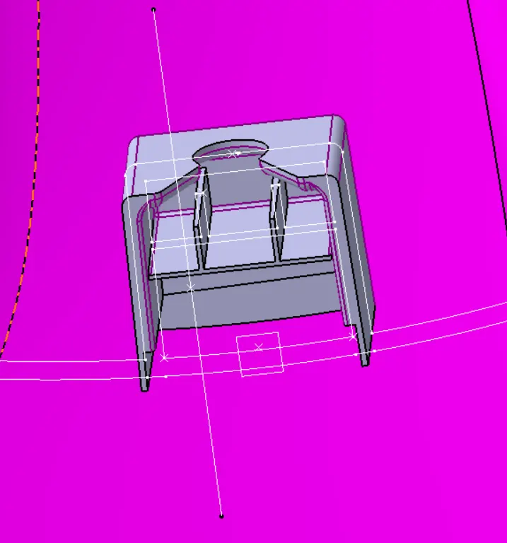
DRAFT ANALYSIS ON THE CLASS A SURFACE:
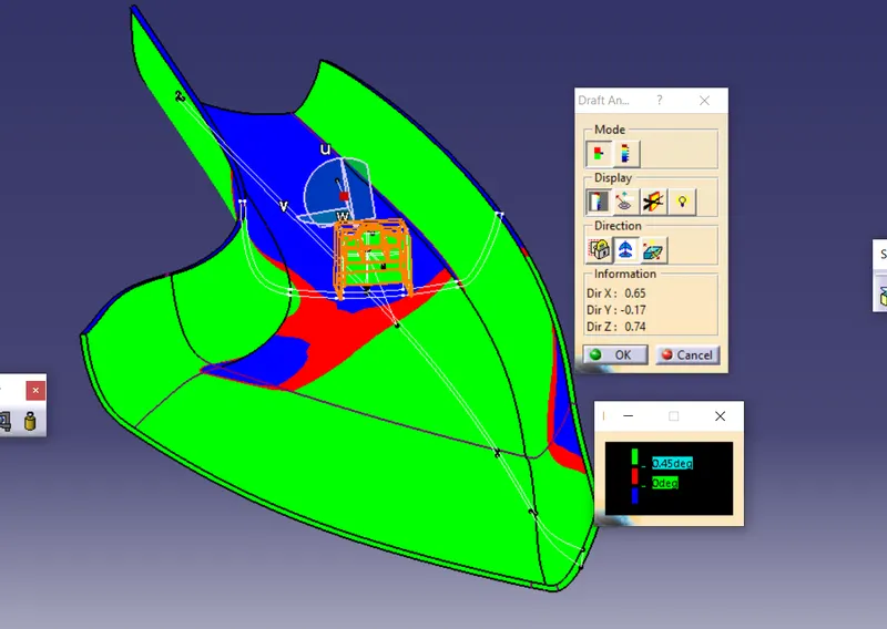
Next, We will perform a Draft Analysis on the Class A Surface itself:
Before starting with a Draft Analysis Operation, we will go to the 'Customize View Parameters' option under the 'View Toolbar'. Then we will enter the 'Customize View Mode' where we will go under the 'Mesh' option and select 'Material' and press 'OK'.
To start the Draft Analysis in the 'Generative Surface Design Workbench', we will go to 'Insert' and then look for the option called 'Analysis'. Once found, we will go under that and click on 'Feature Draft Analysis. This will open the 'Draft Analysis' Dialogue box. There, we will ensure that under 'Mode' we have selected 'Quick Analysis', under 'Display' we will select 'Show or Hide the Color Scale' and then select '3 Degrees' as the permissible draft angle. Then, under 'Direction' we will choose the icon with the symbol of the compass on it which stands for 'Use the Compass to define the new current draft direction'.
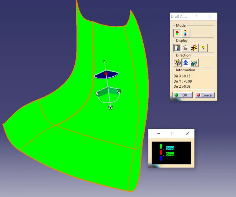
It is evident from the above image that the Draft-Analysis on our Class A Surface was successful and the component is feasible to manufacture.
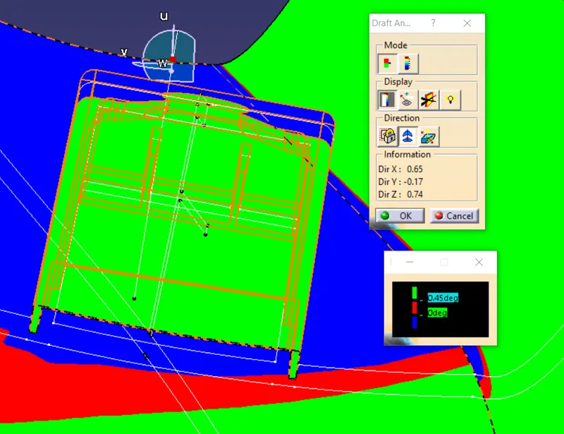
At the region shown below the draft angle is lower than 3 degrees but only by a small amount.
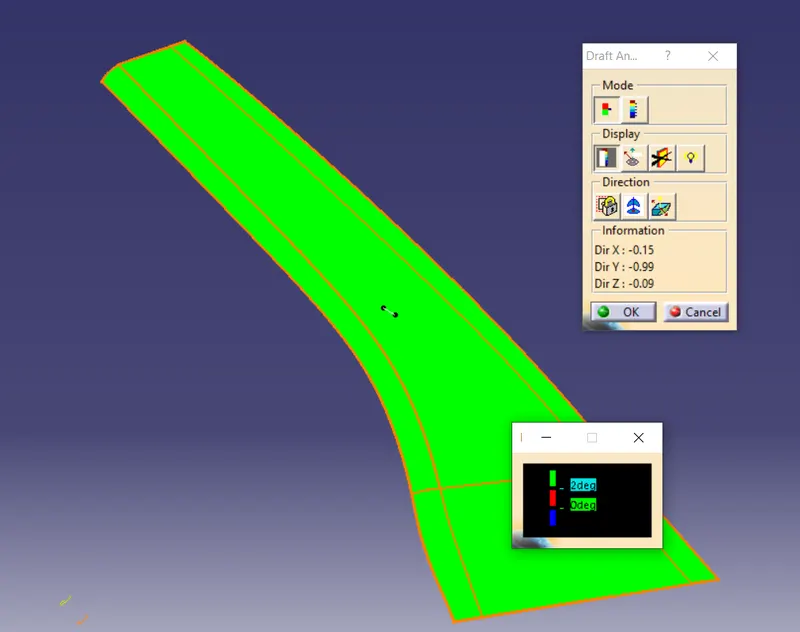
We can communicate this development with the Class A Surface Designer and request them to recreate this region so that it'll clear properly with the Main Tooling Axis but for now we're going to continue with this Class A Surface.
PROCEDURE TO CREATE THE CLASS B SURFACE:
We'll offset the Class A Surface by 2.5mm as shown below:
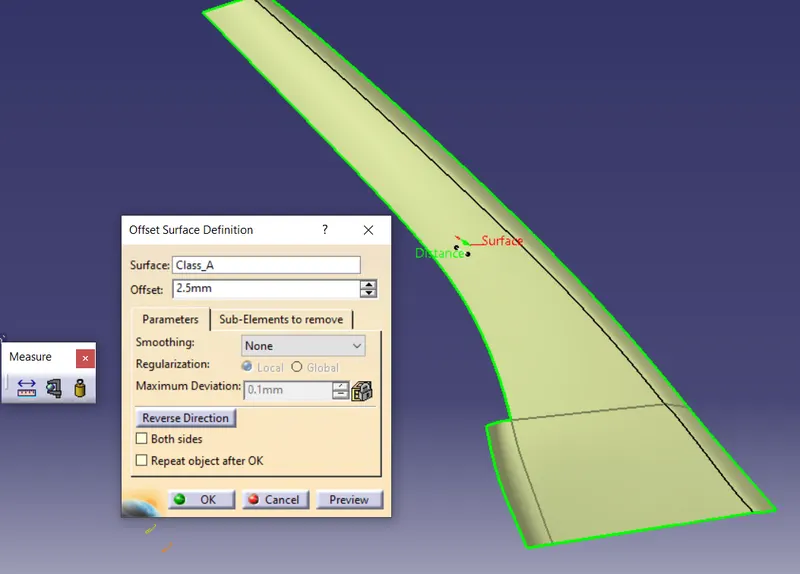
It is not offsetting properly due to the complexity of the curvature of the Class A Surface and hence we have to recreate that missing patch using tools such as Sweep Command as shown below.
We'll create two boundaries as shown below so that we can use the sweep command on it:
We'll create it using Reference Surface in the Sweep Command's Dialogue Box as shown below:
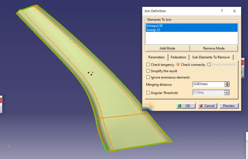
Then, we'll join the newly created surface with the main offset obtained from the Class A Surface.
Hence, our Class B Surface is created.
PROCEDURE TO CREATE THE CLASS C SURFACE:
To create the Class C surface firstly we have to unhide the Class A Surface and extract it's boundaries as shown below:
We're going to smoothen these extracted boundaries using 'Curve Smooth'. Then we're going to use the 'Sweep' command with 'Reference Surface' & 'With Draft Direction' to create the Class C Surface as shown below:
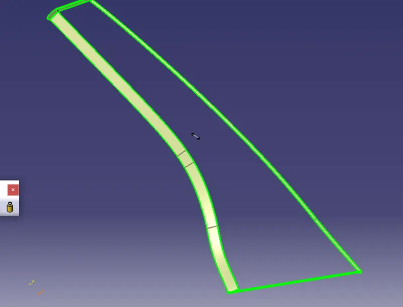
Now, we're going to join the Class A and Class C surfaces with each other.
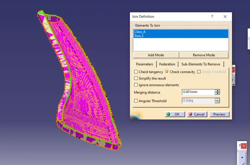
Then, we going to trim it with the Class B surface. To ensure that it will be feasible to trim the Class B surface with the joint surface of Class A & C, we're going to extrapolate the Class B surface by a small amount to obtain the closed body as shown below:
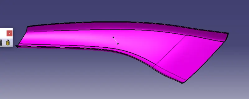
Draft analysis for dog house (side core axis)
This side core axis was only applicable for the dog house. The same o.5 degree minimum draft angle was followed. This are well drafted surfaces looks so drafty.