Week 11: Project 2 - Emission characterization on a CAT3410 engine
Emission characteristic Analysis On Diesel Engine with open-w and Omega shape piston
Introduction
Diesel engines are more efficient than gasoline engines for two reasons: (i) higher cylinder pressure and corresponding higher temperatures lead to improved thermal efficiency for the diesel engine; (ii) the air throttling required to control the gasoline engine power output reduces engine efficiency and is not used on diesel engines. Truck drivers and farmers are very aware of the reduced fuel costs associated with running a diesel engine as compared to a gasoline engine. The trucks and tractors include an extended range of gear ratios so the diesel engine operates at nearly optimum RPM (Rounds Per Minute) as the load changes.
The thermal efficiency of an engine is computed as the ratio the working engine delivers divided by the thermal energy available from the fuel.
Working
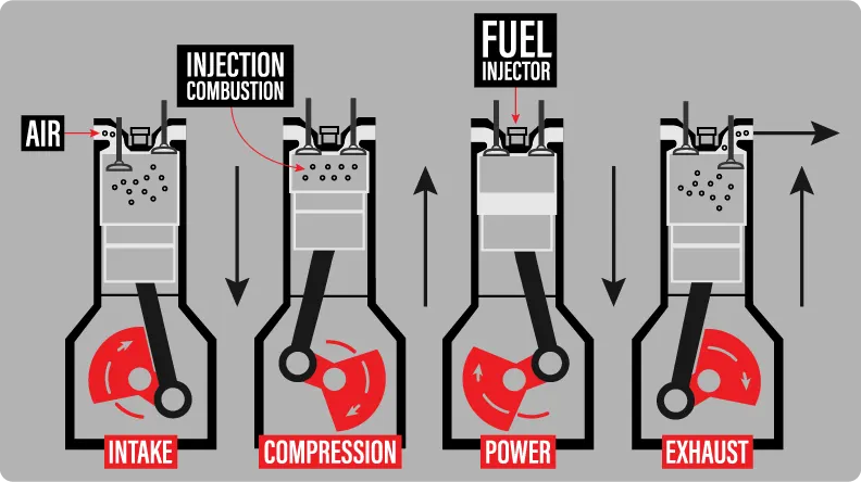
Step 1 INTAKE (DOWN) STROKE 1
The piston moves down drawing air into the cylinder
Step 2 COMPRESSION (UP) STROKE 1
- The piston moves up compressing the newly drawn air in the cylinder
- Before the piston reaches top-dead-center (TDC), diesel fuel is injected directly into the cylinder
- This result is the combustion of diesel fuel
STEP 3 INTAKE STROKE (DOWN) 2
The piston draws down but the intake and exhaust valves are not open
STEP 4 COMPRESSION STOKE (UP) 2
The piston moves up forcing the combusted diesel fuel out of the cylinder in the form of exhaust
A diesel engine offers an efficient method to produce power. It relies on compression for combustion, which results in increased fuel efficiency compared to other types of engines
In the direct injection engine, the air movement takes the form of a swirl about the cylinder axis, which is generated during the induction stroke by a suitable design of the inlet port. The rate of swirl increases during the later part of the compression stroke as the rotating mass of air above the piston moves into the smaller diameter cavity. The principle of conservation of angular momentum suggests that the swirl rate will increase in proportion to the square of the ratio of the two diameters although, as will be, there are a number of complicating factors. At the end of the compression stroke, the airflow pattern is also strongly influenced by a radial movement, known as squish. At TDC the gap between the cylinder head and the piston crown (the “bumping clearance”) is very small. As the piston rises, the air trapped above its surface is forced inwards into the cavity; this squish interacts with the swirl to produce considerable turbulence. In order to increase the swirl, the piston cavity is deeper and of a smaller diameter than that of a quiescent chamber engine.
Emission
Diesel emissions include also pollutants that can have adverse health and/or environmental effects. Most of these pollutants originate from various non-ideal processes during combustion, such as incomplete combustion of fuel, reactions between mixture components under high temperature and pressure, combustion of engine lubricating oil and oil additives as well as combustion of non-hydrocarbon components of diesel fuel, such as sulfur compounds and fuel additives. Common pollutants include unburned hydrocarbons (HC), carbon monoxide (CO), nitrogen oxides (NOx) or particulate matter (PM).
From the government restriction according to BS standard and EURO standard which is an update norm to reduce the pollutant. Engineers and scientists are working on various methods after combustion like the catalytic converter, changing the injection methods, Design changes etc to find the best solution for pollution reduction
Design Analysis
Our analysis is done on open-w and omega profiles to find the performance and emission characteristics in converging CFD
For system, power Demand it is better to analyze section view of the cylinder from the entire 360 models because mathematically it solves radially.
Geometry
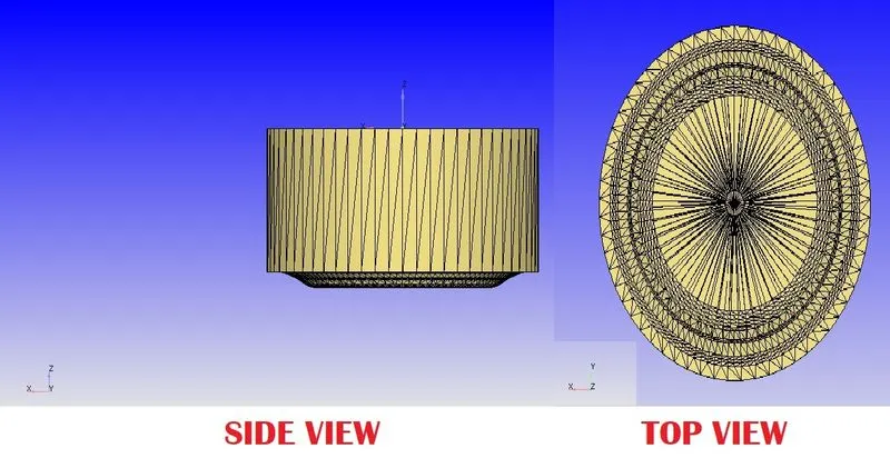
Model Creation using profiles
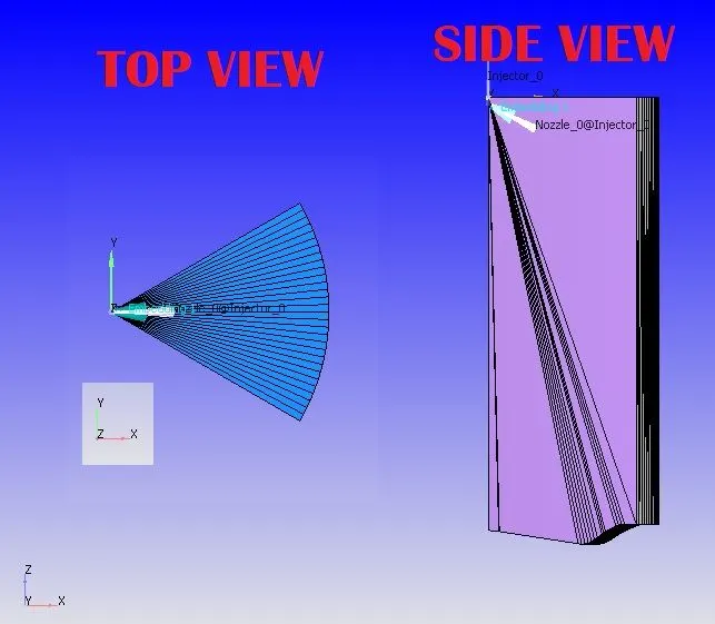
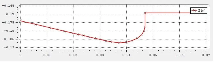
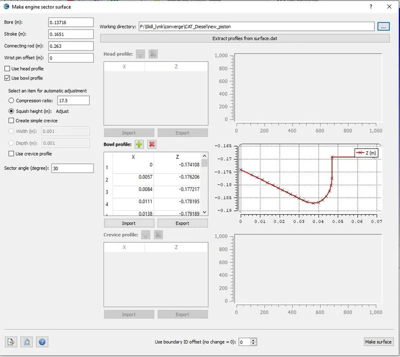
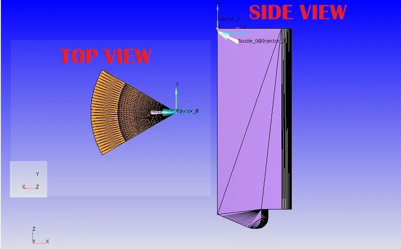
Tools-Make engine sector surface by giving details Bore=0.13716 m, store= 0.1651 m, connection rod= 0.263 m, compression ratio= 17.5 we can extract the section surface for analysis, 45 degree of model extraction by section angle option
Open-w
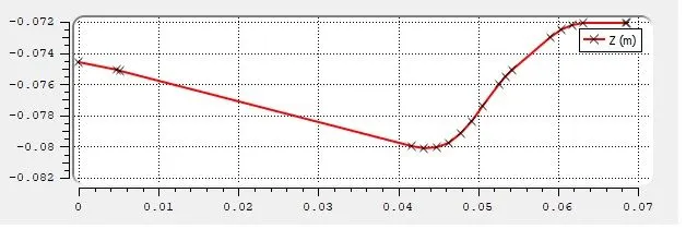
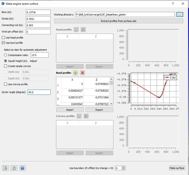
Extraction Part Geometry
Omega
Extraction Part Geometry
Boundary Condition
| Application type | crank angle-based IC Engine | |||
| Physical Parameter | ||||
| cylinder bore | 0.13716 | m | ||
| stroke (2*crank radius) | 0.1651 | m | ||
| crank speed | 1600 | RPM | ||
| Reference | ||||
| piston surface ID | Piston | |||
| Liner ID | cylinder wall | |||
| Head ID | cylinder head | |||
| Materials | ||||
| Gas Simulation | ||||
| import therm.dat | ||||
| Parcel simulation | ||||
| Predefined liquids from that select DIESEL2 | ||||
| Reaction Mechanism | ||||
| Select mech.data file and check the property loaded | ||||
| species | ||||
| parcel | Query available list to select Diesel 2 | |||
| Simulation Parameters | ||||
| Run parameters | ||||
| solver | Transient | |||
| temporal type | crank angle-based Engie simulation | |||
| simulation mode | full hydrodynamic | |||
| Gas flow solver | compressible | |||
| Liquid flow simulation | Incompressible | |||
| Simulation parameter | ||||
| start time | -147 | degree | ||
| End time | 135 | degree | ||
| initial time-step | 5.00E-07 | s | ||
| Minimum time-step | 1.00E-08 | s | ||
| Maximum time step | 2.50E-05 | s | ||
| Solver parameter | ||||
| Navier-strokes solver scheme | PISO | |||
Boundary Conditions
Piston
Boundary Type- wall
wall motion type- translating
Surface movement- moving- Law of wall- piston motion
Temperature- law of wall- 553 k
Front_face
Boundary Type- Periodic
Periodic Type- stationary
Periodic shape- Rotational
Angle- 45
Back_face
Boundary Type- Periodic
Cylinder_wall
Boundary Type- Wall
wall motion type- stationary
surface movement- Fixed- law of wall
Temperature- law of wall- 433 k
Cylinder_head
wall motion type- stationary
surface movement- Fixed- law of wall
Temperature- law of wall- 523 k
Initial Conditions and Events
From stoichiometric balance
`C_xH_y+a(O_2+3.76N_2)rarr xCO_2+(y/2)H_2O+3.76aN_2`
`a=x+y/4`
from this extraction product
`C_7H_16+11(O_2+3.76N_2)rarr7CO_2+8H_2O+41.36N_2`
convert molar fraction to input data
Region name- In_cylinder_region
| Region | ||
| In cylinder region | ||
| Temperature | 355 | k |
| Pressure | 197000 | pa |
| Species | ||
| CO2 | 0.0014304 | |
| H2O | 0.0006296 | |
| N2 | 0.76765 | |
| O2 | 0.23029 | |
| Total | 1 | |
| Passive | ||
| Hiroy soot | 0 | |
| Nox | 0 | |
Physical Model
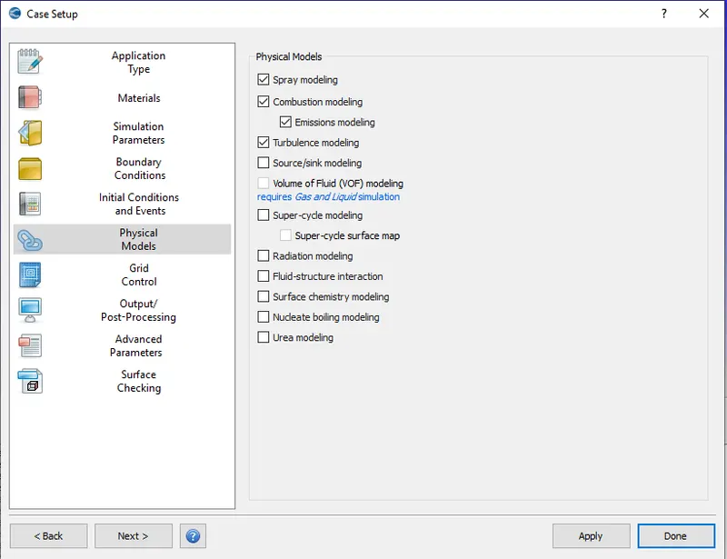
switch on spray modeling, combustion modeling emissions modeling, Turbulent
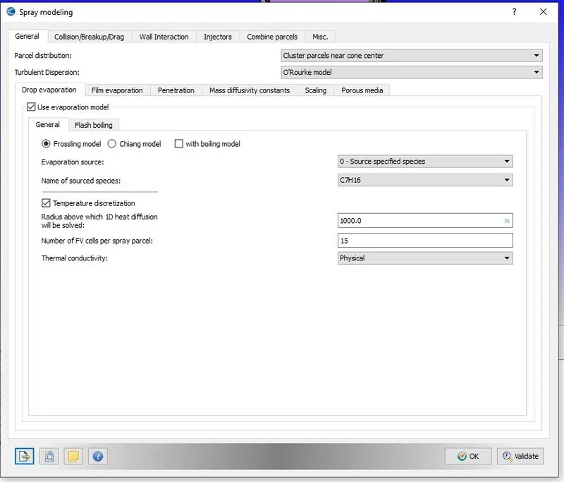
Spray modeling
General
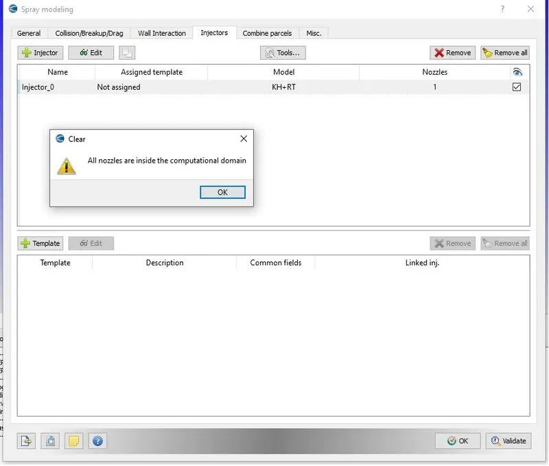
Injectors
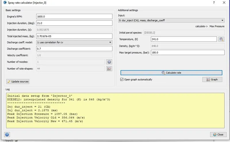
Initial data setup from 'Injector_0'
DIESEL2: interpolated density for 341 (K) is 848 (kg/m^3)
Sources updating: No changes detected. Skipped.
********************************
Inj dur_inject = 21 (CA)
Inj dur_inject = 2.1875 (ms)
Peak Injection Pressure = 1097.05 (bar)
Peak Injection Velocity Old = 356.064 (m/s)
Peak Injection Velocity New = 471.45 (m/s)
Spray Rate output graph
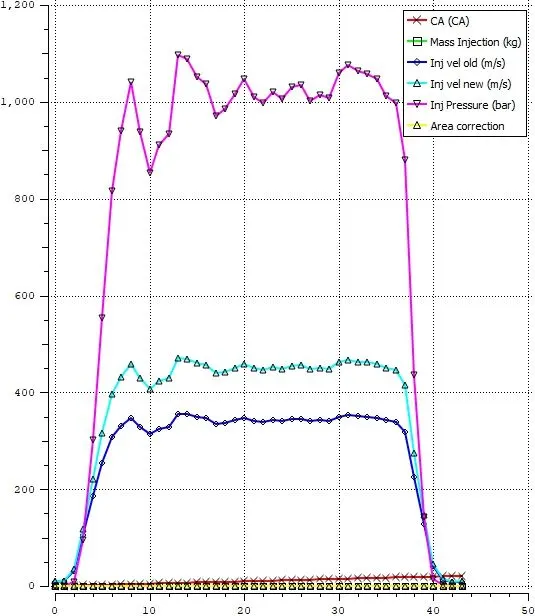
Injector configuration
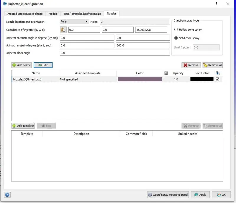
Nozzle position
Nozzle diameter-0.000259
spray cone angle-9 degree
circular injection radius-0.0001295
spray
Injection Rate shape
Profile rate shape plot
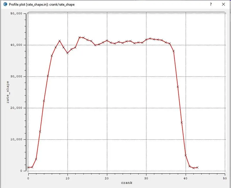
injection profile important
Time/Temp/Mass
| Fuel Calculation | |
| RPM | 1600 |
| Fuel mass per cycle | 2.70E-05 |
| RPS | 26.6666667 |
| DPS | 9600 |
| Time per Degree | 1.04E-04 |
| Time per 720 Degree | 7.50E-02 |
| Fuel flow rate | 3.60E-04 |
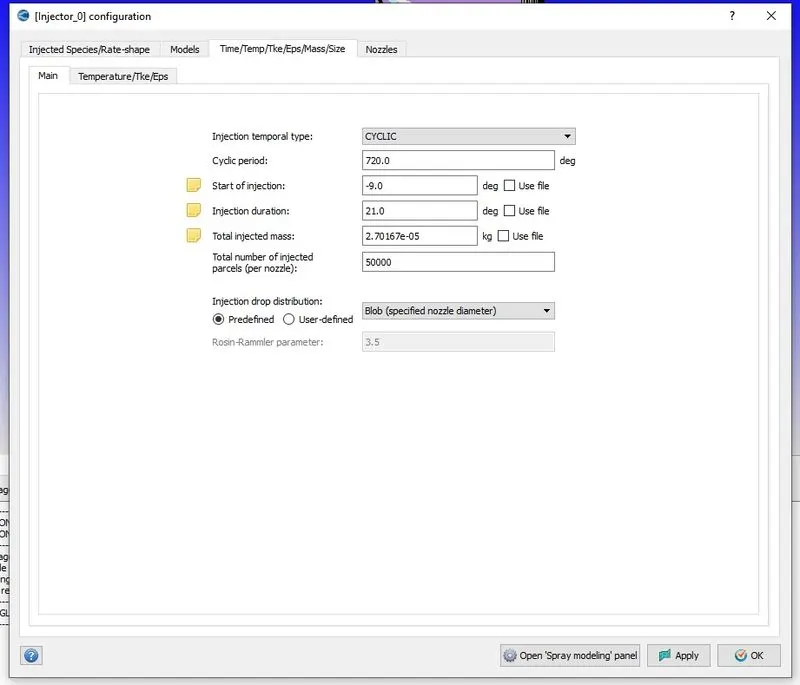
Combustion
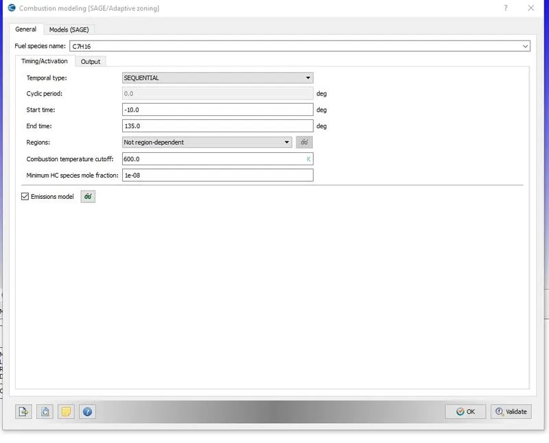
Timing starting time=-10 deg, end time=135 deg
Combustion- Models
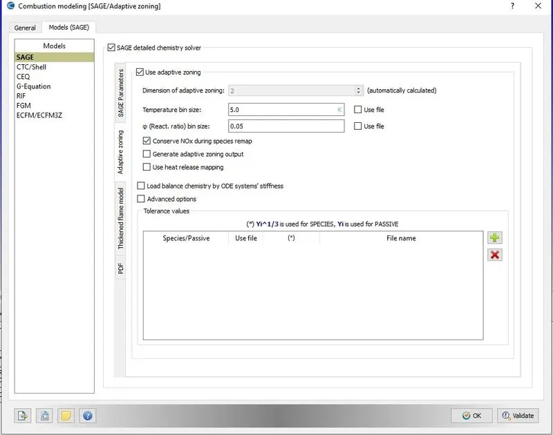
Combustion- Models-emission
on-Nox model-Thermal Nox model (Extended Zeldovich)
on-Hiroyasu-NSC soot model
Turbulence
RANS-RNG-`k-epsi`
Grid Controls
Base grid
dx,dy,dz-0.004 m
AMG
velocity & Temperature for an accurate result by finer mesh in setup output data
maximum cells:2000000
Releasing Frequency:25
Velocity
Embedded type; SGS
max embedded level- 2
sub-grid criteria - 2 m/s
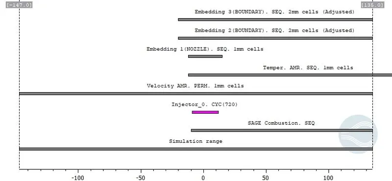
checking Time scale Data
timing control - permanent
use AMR when parcel count exceed-50
Temperature
Embedded type; SGS
max embedded level- 2
sub-grid criteria - 5 k
timing control - Sequential
start=-12 degree
end=180 degree
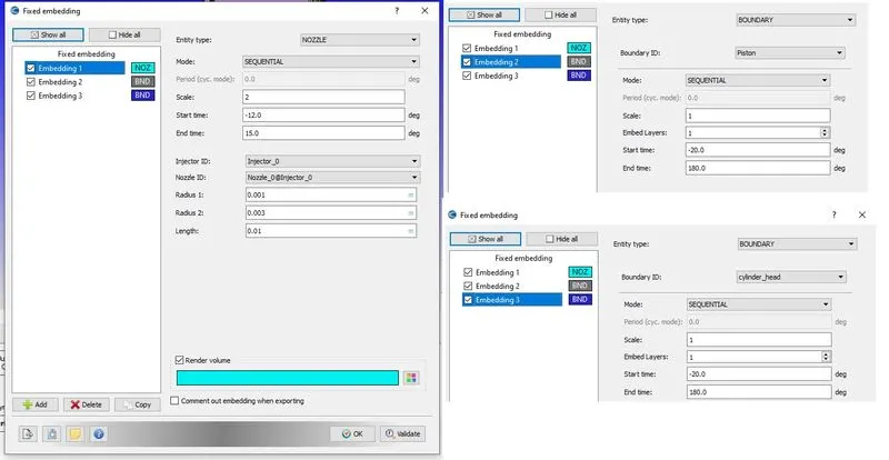
Fixed Embedding
Embedding1
for nozzle
mode-sequential
scale=2
start time=-12 degree
End time=15 degree
Radius1=0.001
Radius2=0.003
Legth=0.01
Embedding2
piston
mode-sequential
scale=1
embedded layer=1
start time=-20 degree
End time=180 degree
Embedding3
cylinder head
mode-sequential
scale=1
embedded layer=1
start time=-20 degree
End time=180 degree
checking Time mapping
Simulation Output
openw
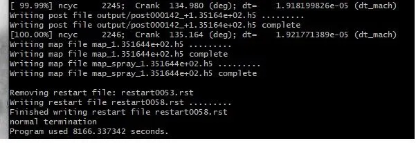
Omega
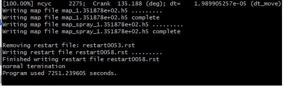
openw took 8166.34 sec to complete the analysis is power-consuming compared to omega.
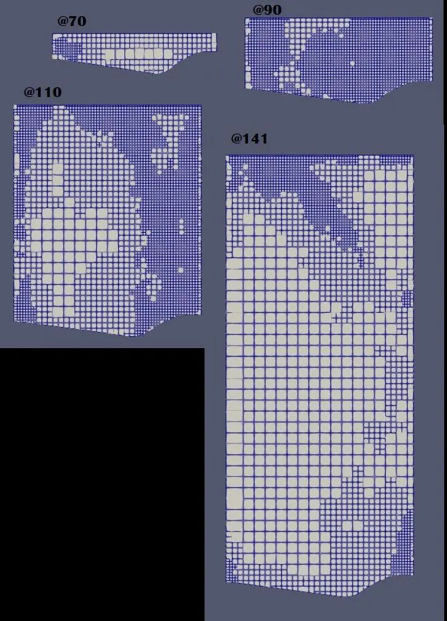
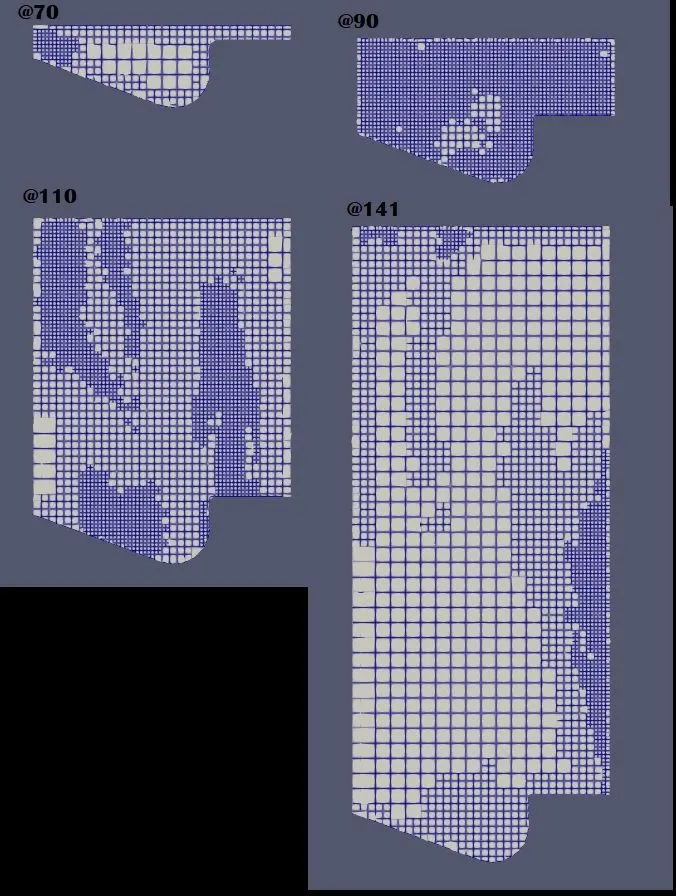
Mesh
at time step 70 combustion starts where properties are changes -9 degree onwards
variable time step
openw
omega
Contours
openw
Fuel
H2O
Pressure
Temperature
velocity
Emission
CO
Co2
NOx
omega
fuel
H2O
Pressure
Emission
Co
Co2
Nox
Graphs
a comparison study on both openw and omega Design for all functional properties with respect to crank angle
Fuel vs Crank angle
Suction -150 to -50 degree
combustion start -50 degree to 15 degree
power -9 to 29
exhaust stroke 40 to 120 degree
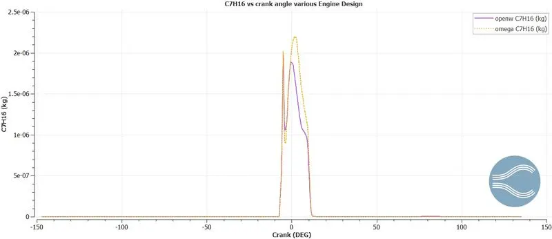
fuel start injecting -9 to 21 degree where due to design peak fuel (C7H16) which is 2.2e-6 kg penetrated in omega profile piston
Temperature Vs Crank angle
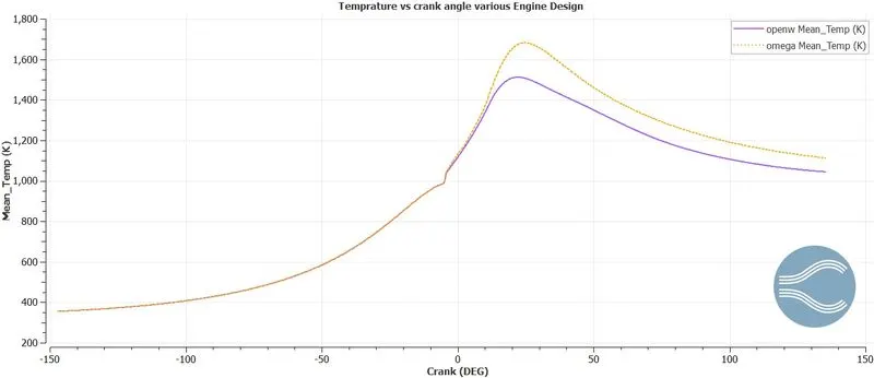
The temperature took maximum at
1490k @ 25 degrees for openw piston
1650k @ 25 degrees for omega piston
design by comparing omega piston engine has a maximum peak temperature
Pressure Vs Crank angle
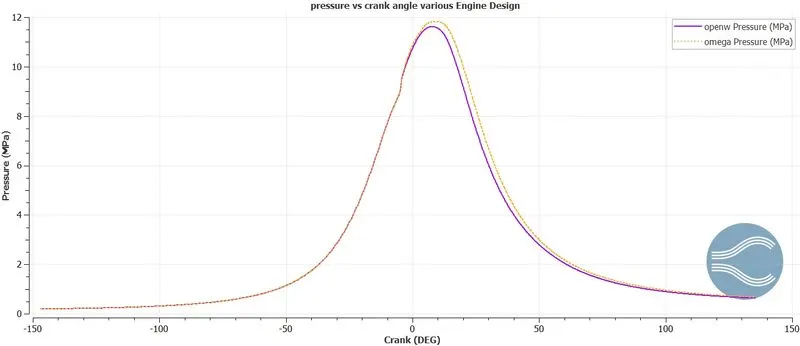
maximum 10.8MPA pressure @ 15 degrees for openw
maximum 11.8MPA pressure @ 15 degrees for omega
by comparing both designs which is omega piston give maximum pressure
Cell count Vs Crank angle
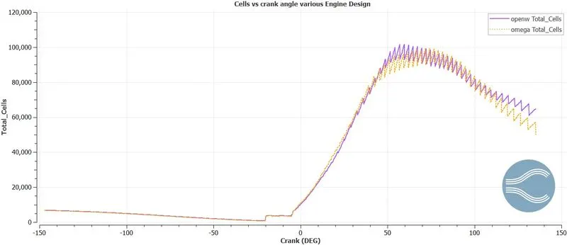
Due to AMT from 0 degrees to 45 degrees, gradually cell count increases at peak temperature and pressure at 50 degrees mesh size increase to capture physics open w took high cell count fluctuation and system power compared to omega
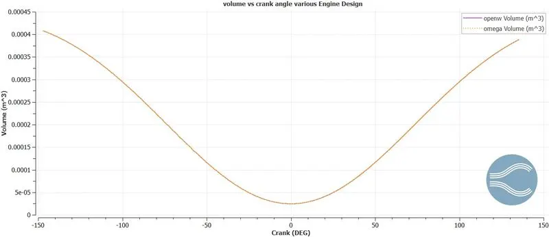
Volume vs crank angle
Co2 Vs Crank angel
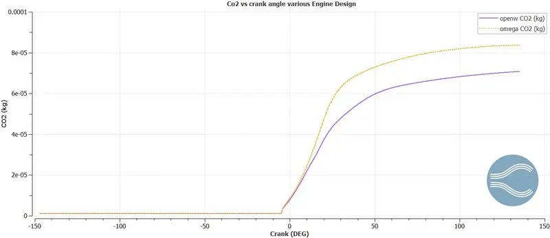
-9 degrees onward there is CO2 increases gradually at a peak temperature condition after combustion omega release Co2 at 8.2e-5 kg in omega which is high
Co Vs Crank angel
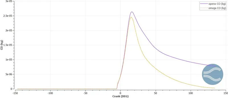
-9 degrees onwards there is a linear increment in coequally at peak temperature where the end of the combustion omega start releasing least co 2.4e5 kg which defines complete combustion than openw piston
Nox Vs Crank angel
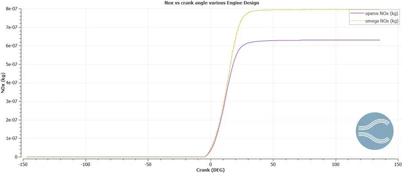
openw piston gives Nox=6.2e-7 kg the least temperature where higher temperature obtain higher Nox formation in fuel so omega complete combustion compare to omega Nox=8e-7kg
Integrated Heat Release Rate vs crank angle
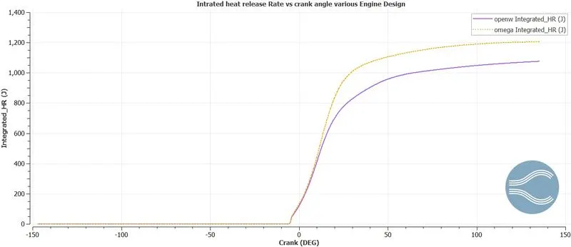
omega release maximum= 1200 J
SOOT vs crank angle
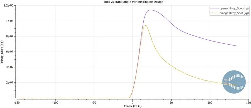
minimum volume omega soot=9.5e-7 kg maximum and release gradually
Engine Performance
Torque
power=(work done/time)
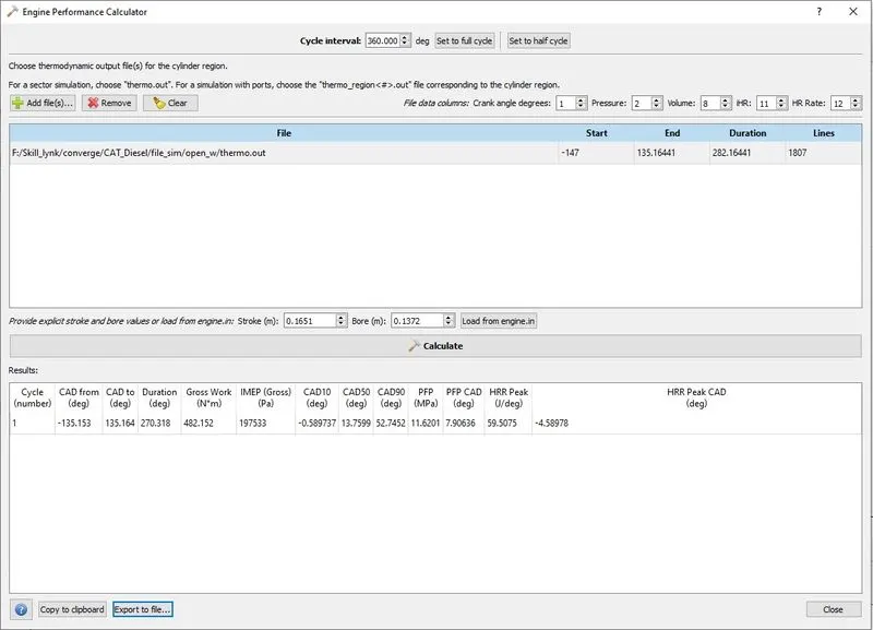
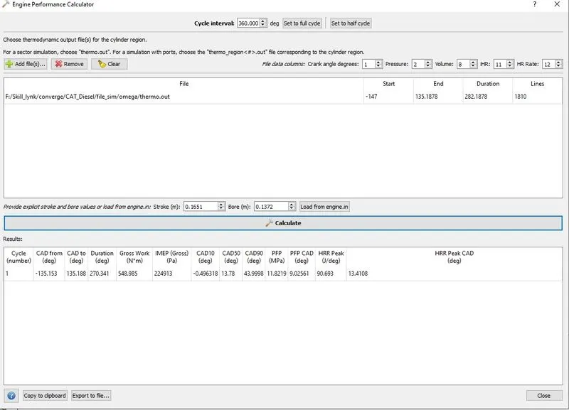
In Engine performance calculator
apply
- Bore =0.1372 m
- Stroke = 0.1651 m
- to get the value of engine performance
| RPM | 1600 |
| Fuel mass per cycle | 1.01E-05 |
| Rotation Per Sec | 26.6666667 |
| DegreePerSec | 9600 |
| Time per Degree | 1.04E-04 |
| Time per 270.278 Degree | 2.82E-02 |
combustion timing=5.55e-5 s
from that, we can calculate the power
power=work/time
Torque
from power `P=(2⋅π⋅N⋅T)/60`
`T=(P*60)/(2⋅π⋅N)`
Open-w
Omega
calculation
open-w
power=work/time
Power=482.152/0.028154
P=17.126kw
from power
`T=(P*60)/(2⋅π⋅N)`
`T=(17126.52*60)/(2*1600*pi)`
`T=102.2623 Nm`
open-w
power=work/time
Power=548.985/0.028154
P=19.4993kw
from power
`T=(P*60)/(2⋅π⋅N)`
`T=(19499.32*60)/(2*1600*pi)`
`T=116.437 Nm`
comparing design
| S.no | Description | openw | omega | Difference | units |
| 1 | work | 482.152 | 548.985 | 66.833 | Nm |
| 2 | Torque | 0.102262 | 0.116437 | 0.0141747 | Nm |
| 3 | power | 17.12552 | 19.499317 | 2.3737935 | w |
| 4 | IMEP | 197533 | 224913 | 27380 | Mpa |
| 5 | CAD10 | -0.58974 | -0.496318 | 0.093419 | degree |
| 6 | CAD50 | 13.7599 | 13.78 | 0.0201 | degree |
| 7 | CAD 90 | 52.7499 | 43.9998 | -8.7501 | degree |
| 8 | IHR_max | 1050 | 1200 | 150 | J |
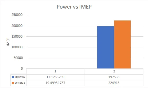
conclusion
where omega has higher Heat releasing rate and maximum function of properties such as temperature, pressure, etc with respect to crank angle.
NOx in the omega engine’s exhaust emission is due to high combustion temperature which reacts with nitrogen in the air supplied for combustion.
CO, CO2 emission is lesser in omega which is describe complete combustion
compare to openw & omega give Power =2.3737935 w more than openw