Week 11: Project 2 - Emission characterization on a CAT3410 engine
Emission characterization on a CAT3410 engine
Aim:-
- Simulate with both open-w and omega pistons.
- Explain the simulation setup.
- characterize the emissions (Soot, NOx, and UHC)
- Create animations showing the variation of all the engine parameters.
- Compare the indicated mean effective pressure and power values graphically.
In this project, two simulations were performed on the same combustion chamber geometry and set up with the different head profiles of the piston - Open-w and Omega.
Surface Preparation with CONVERGE Studio for DIESEL Engines:-
For the surface preparation, the 'make engine sector surface' option available in converge was used.
To understand what is the significance of the 'make surface option' let's first discuss the parameters of the given geometry. geometry depicts the close engine cylinder what we can call is the combustion chamber. Where the entire piston top surface is there as well as the cylinder liner and cylinder head is there. But we do not have any valves or ports. This is what you called the close cycle analysis where you are doing all the analysis when all the valves are closed. For the close cycle simulation, it is completely ok to remove all valves or ports for computational efficiency.
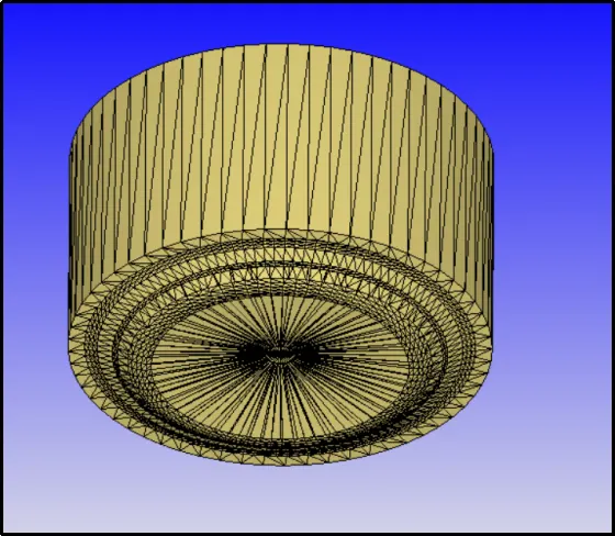
For the diesel engine, most probably the injector is mounted on the center of the cylinder head and the injector is going to have multiple nozzles.
Now, what we can do is for computational efficiency, we can consider one sector of the combustion chamber domain and simulate combustion in it. The obvious advantage of doing it this way is computational efficiency which will provide us with faster run times. To create the sector surface, the 'make surface option' in converge comes into play. This option can be found in - Tools -> Make engine Sector surface.
To accomplish this task, we need combustion chamber specifications and piston profiles. Getting a piston profile is very hard. To simplify this task converge provides the Extract profile option. The idea of getting a profile is very simple. We have to cut the combustion chamber and we will get its complete profile on the plane and then we can get the piston profile.
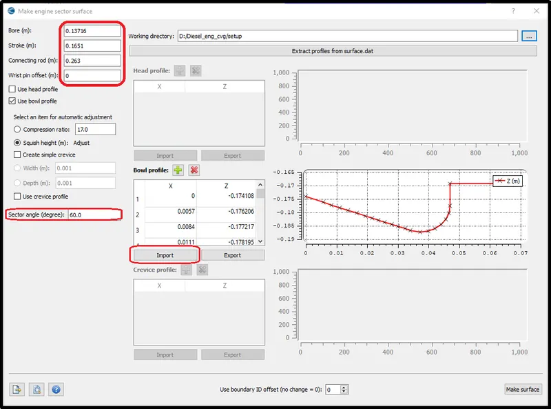
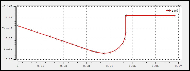
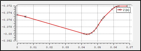
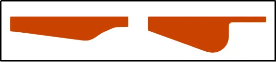
In this project, the CFD simulation was performed on the two types of piston heads. One is OMEGA head type piston and another one is open-w. The below pictures shows the profile for both piston heads respectively.
After the simulation, the comparison of these two simulations is analyzed in the result section of this report.
Simulation Case setup:-
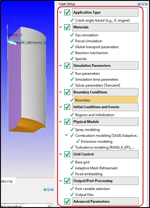
The following is the setup tree for the No hydrodynamic simulation case.
IC engine specifications:-
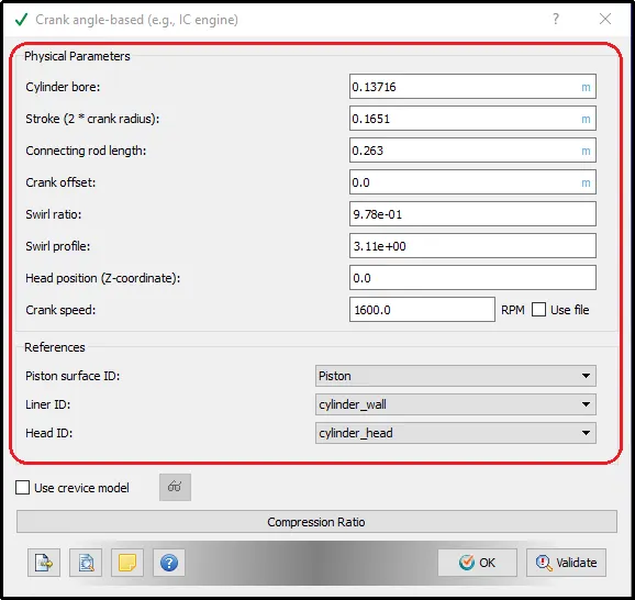
Specify the Engine Parameters in the below window.
Parcel Simulation:-
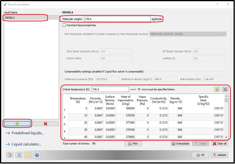
From the liquid database select DIESEL2.
Species Definition:-
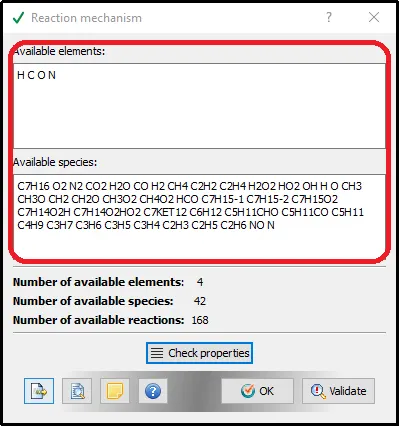
Feed the mech.dat file data in a Reaction mechanism setup.
The Reaction mechanism setup reads all the species data from the mech.dat file and shows it in the available species box.
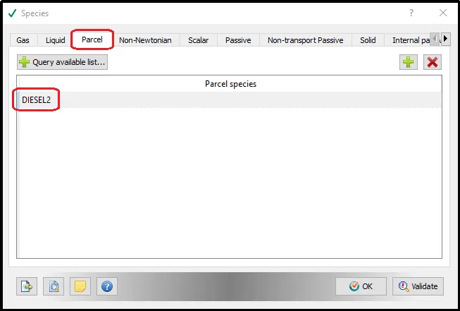
Species Definition (for Parcel):-
Now, in the species section, the selected partial species was defined. Here, we did not need to define all the species that we are using as we already defined it in the reaction mechanism. We only have to define the liquid species from the partial species.
Run Parameters:-
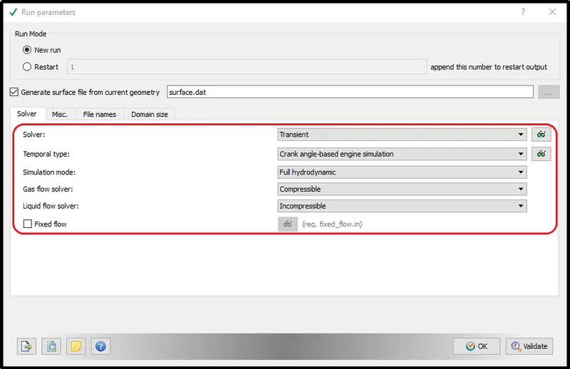
This is the transient type of simulation concerning the crank angle motion. Combustion is happening in this simulation type, so, it is vital to run the setup with full Hydrodynamic simulation mode.
And, As the air and Vaporization of Diesel are involved Gas flow type is compressible and for the liquid spray, it is incompressible.
Simulation time parameters:-
In the Simulation time parameters setup, we define the start crank angle and end crank angle.

Boundary Conditions:-
The boundary conditions were provided to all the wall and inlet-outlet boundaries.
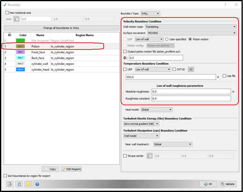
Piston Wall:-
The piston wall surface is the moving surface, therefore select translating and moving option with the low of the wall.
Make sure that the Piston motion option is turned on otherwise the piston will not move in simulation.
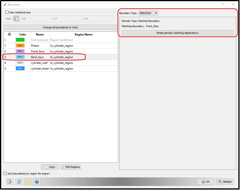
Front Face:-
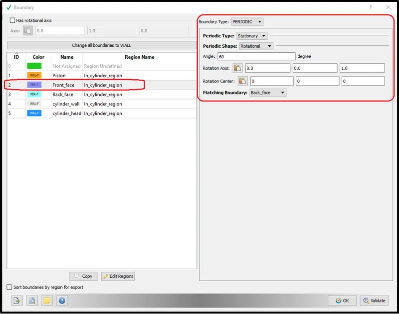
It is that surface, from which sector part of the combustion chamber is cut out. So we have two of those surfaces - front and back.
For both the surface providing periodic angle and following specification is extremely important to simulate without any error.
Back Face:-
By using the matching boundary option in one surface setting we can provide the same boundary condition for the other surface. So, we are providing similar boundary conditions to the back face.
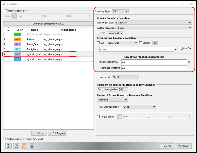
Cylinder wall:-
The cylinder wall will be stationary, through the simulation so the only working temperature is provided to the setup.
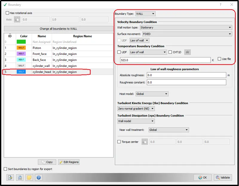
Cylinder head:
similarly, for the cylinder head, the wall motion type will be stationary as this is the stationary part. and the working temperature for the cylinder head will be higher than the cylinder wall.
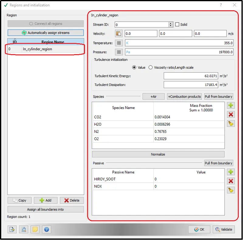
Regions Definition and Initialization:-
In the region, define different regions in the geometry.
Spray Modelling:-
CONVERGE has two types of fluid injection parameters: tubes and syringes. An injector is a group of nuzzles. In CONVERGE you can set up local connection systems, which help you to better prepare and apply the geometry of the injector nuzzles inside. For applications such as internal combustion engines, fuel spray starts, disperses, and dissipates very quickly with very little local scale.
Parcel Distribution:
In parcel distribution, the Distribution parcels evenly throughout the cone was selected to get the proper distribution from fuel spray.
Turbulent Dispersion:
CONVERGE offers the O’Rourke, Kuhnke, and Bai-Gosman film splash models. For after-treatment simulations, the Kuhnke model is commonly used. By altering model parameters like the rebound Weber number and non-dimensional critical wall temperature, you can alter model parameters to correlate the model to experimental results. The Wruck heat transfer model is also available to account for the Leidenfrost effect.
Here, the O’Rouke model was selected for this gasoline combustion simulation.
Evaporation source:
For the Evaporation source, the source specified species option was chosen.
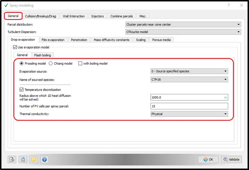
The burning process can be greatly affected by the exact type of fuel spray: droplet velocity, size, distribution, and physical characteristics. CONVERGE allows you to adjust the level of accuracy of measuring fuel injection with the specific needs of your research. You can analyze the injection of liquid fuel using blob injection body models, injection distribution, variable dosage, coefficient output, and a hollow cone and solid cylinder sprays.
Injection Configuration:
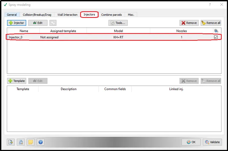
To configure the injection parameter add the injection parameter in the injectors section.
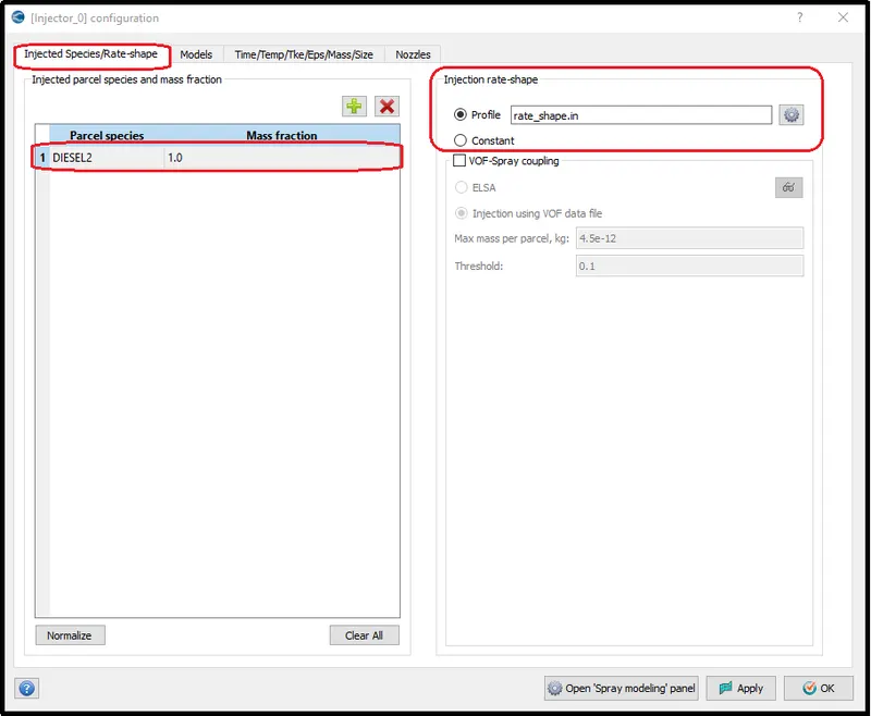
Injector Species and Rate-shape:-
Here we are going to provide our liquid fuel in the parcel species column and We can set the injection rate shape or we can keep it constant.
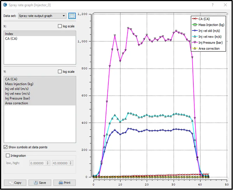
Spray Rate Graph:
The following picture shows, how the injection rate of the fuel change with the crank angle. This graph is obtained from tools - Spray rate preview, where we can see the graph of rate shape, penetration velocity, injection pressure, etc. concerning crank angle provided in rate shape.
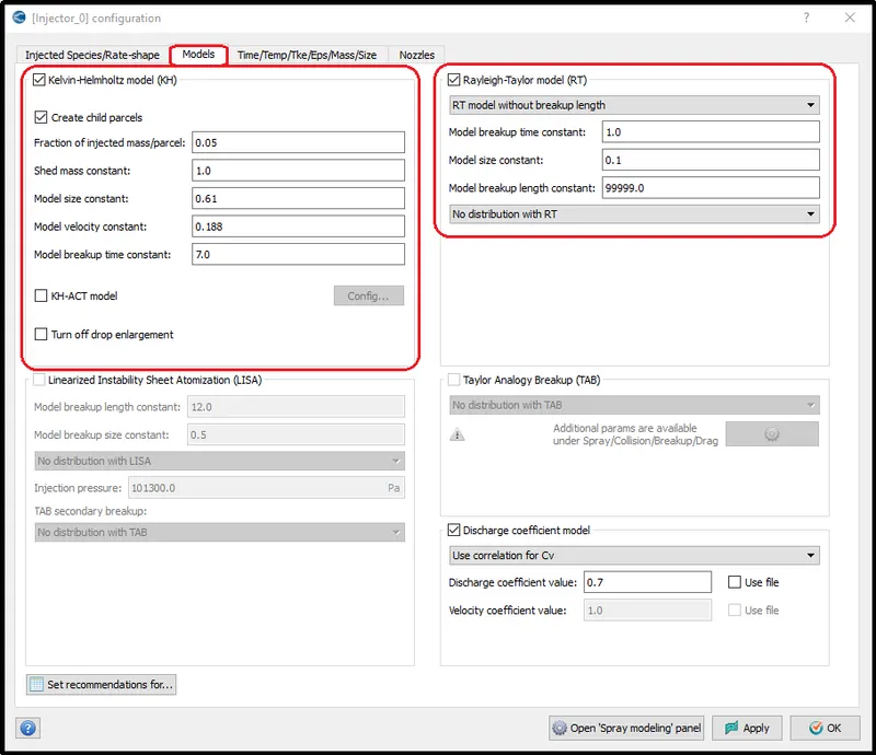
Models:
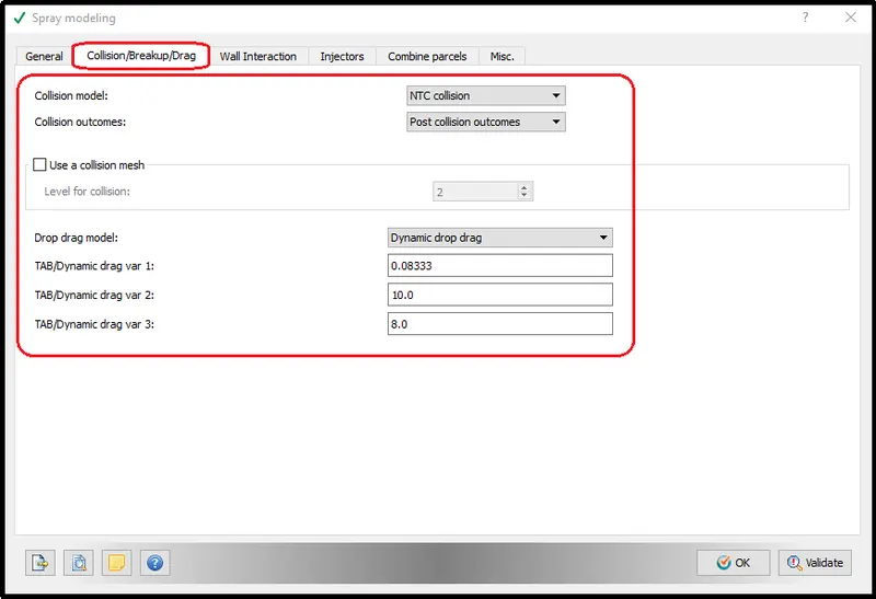
Enable create child models and Rayleigh-Taylor model (RT) and all other condition was kept default.
The above-selected constants control, how the parcels going to break up. So in the Rayleigh-Taylor method, there is an equation called a stability equation or dispersion equation that calculates how long it will take for dispersion of the parcels.
Finally, use a set recommendation for the option to set the required recommended parameter for the selected fuel.
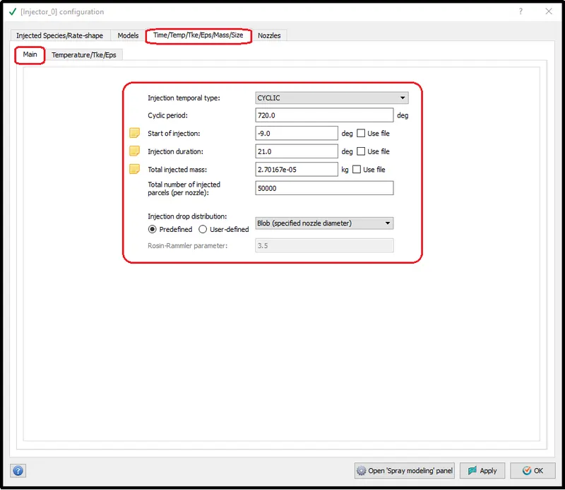
Time/ Temperature / mass/ size:-
Following parameters was set for Time/Temperature/mass/size option.
Nozzles definitions:-
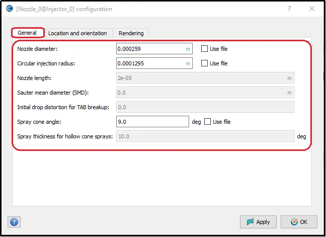
In the nozzle section, the nozzle was created using add nozzle button and its parameters were set by referring to its actual position.
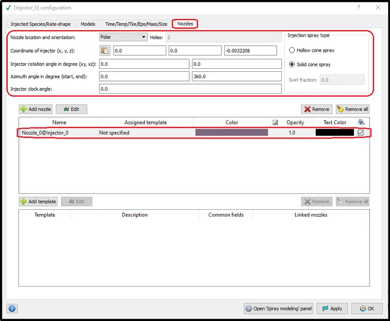
The below information was provided to set the nozzles geometrical parameters
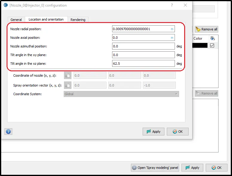
The following are the parameters about the nozzle location and its position related to its angle of spray.
The following animation shows, how the spray modeling works with stationary pistons without automatization in the chamber.
Combustion modeling Setup:
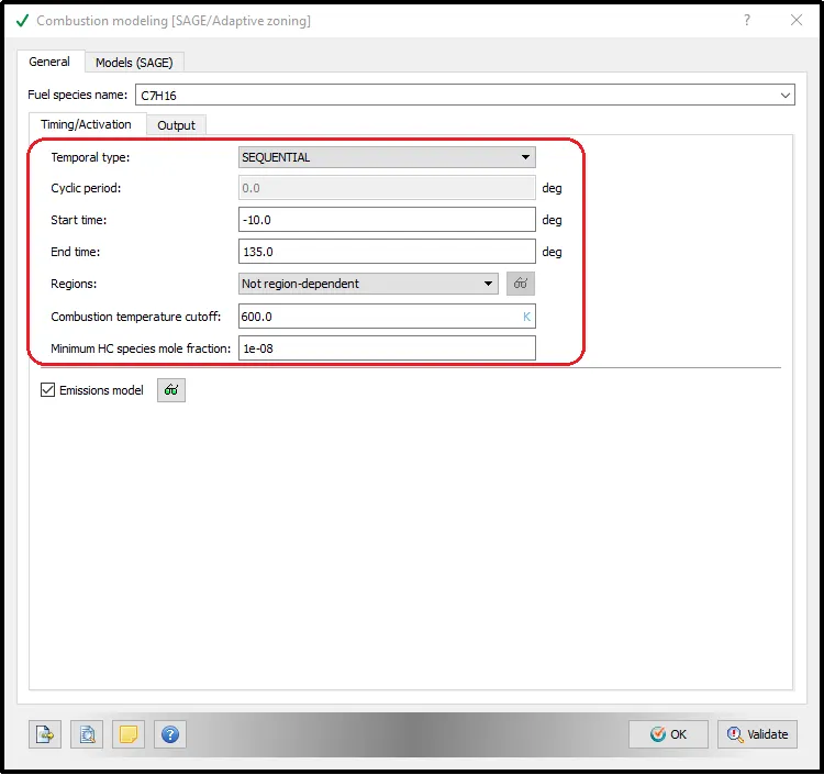
In the combustion modeling setup, the information for the Cyclic period, Start time, End time, Regions was provided as shown in the picture.
Combustion Modelling:-
Combustion facilitates the energy transfer in the engine. Converge contains a detailed chemistry solver and simplified combustion models.
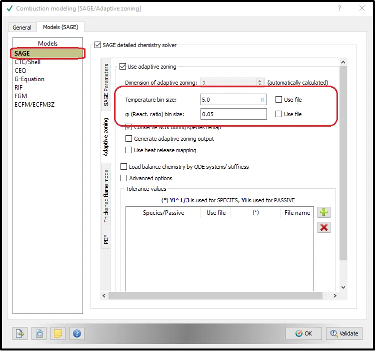
In this project, the SAGE model is used which solves detailed chemical kinetics.
SAGE: the SAGE detailed chemistry solver is a genera combustion model used to solve the detailed chemical kinetics in the combustion process. It can accurately model ignition and laminar flame propagation. It uses local conditions to calculate reaction rates based on the principles of chemical kinetics. Also, determines the kinetically limited phenomenon of engine knock and emissions.
It requires CHEMKIN-formatted input fils to solve the reaction rate ODEs. The ODE solver used is called a CVODE solver. SAGE couples with transport solver via source terms in the species transport equations. A chemical reaction mechanism is a set of elementary reactions that describe an overall chemical reaction. The combustion of different fuels can be modeled. SAGE calculates the reaction rates for each elementary reaction while the CFD solver solves the transport equations. Given an accurate mechanism, SAGE (in addition to AMR) can be used for modeling many combustion regimes (ignitions, premixed, mixing-controlled). You can use SAGE to model either constant volume or constant pressure combustion.
Emission modeling:-
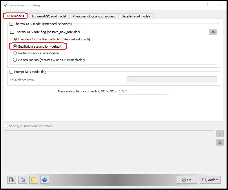
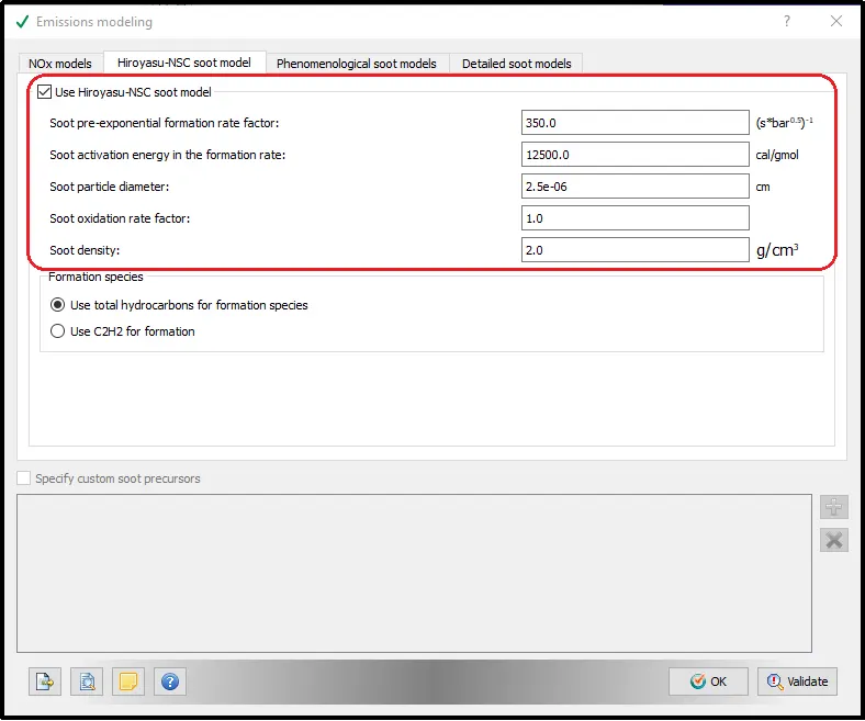
In this project, we will discuss CONVERGE’s emissions modeling options for soot, NOx, unburned hydrocarbons, and CO. We will look at CONVERGE’s acceleration strategies that make it feasible to use even detailed soot models (which includes gas-phase chemistry for its many sub-processes, such as formation via precursor-species, coagulation, and oxidation) in complex simulations.
Turbulence Model:-
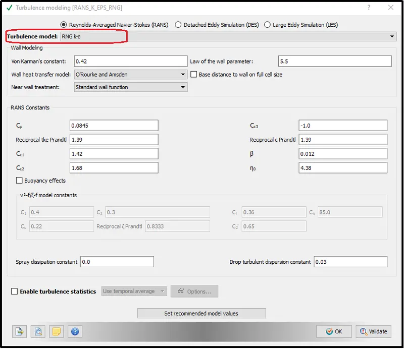
Here define RNG k-e as a turbulence model.
Base Grid:-
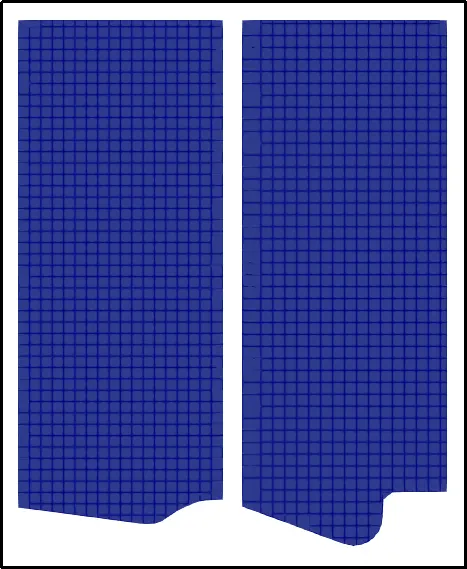
Result of the base grid generation:-
Adaptive Mesh Refinement:-
To powerfully capture the important physics of the injection process, you need a high-resolution grid around the spray. However, you do not need high maintenance far from the spray or before the fuel is applied. Our automated Adaptive Mesh Refinement (AMR) technology provides the decision you need when and where you need it: in spraying conditions, near injections, and spray paths. The combination of AMR and powerful spraying models makes CONVERGE particularly well-suited to help you achieve the best grid conversion results promptly.
Adaptive Mesh Refinement is a method of adapting & enhancing the accuracy of a solution within certain sensitive or turbulent regions of simulation, dynamically and during the time the solution is being calculated. When solutions are calculated numerically, they are often limited to pre-determined quantified grids as in the Cartesian plane which constitutes the computational grid, or 'mesh.
`"Grid size" = "Base grid" / "2 embed level"`
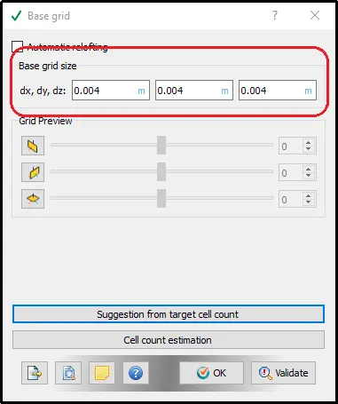
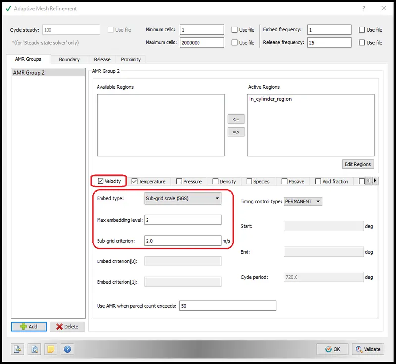
Converge calculates the second order of the variable with the application of AMR embedding and while calculating if the difference is above the Sub-grid criterion, it will perform a refinement of the cells with embed level as provided. The base grid is 0.004m.
Velocity SGS: It is permanent with an embedding level of 2 for SGS of 2 m/s.
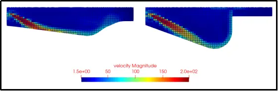
Result of the velocity AMR:-
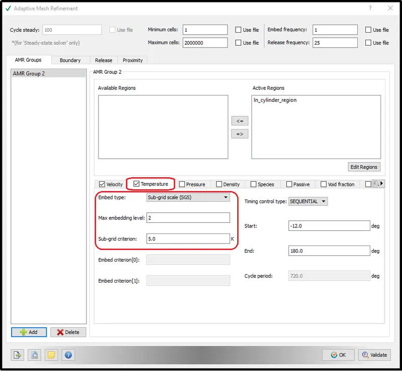
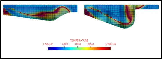
Temperature SGS: It is sequential with an embedding level of 2 for SGS of 5k after the fuel is injected into the combustion chamber.
Result of the temperature AMR:-
Fixed embedding:-
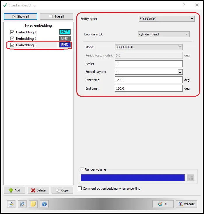
To refine the mesh near the walls and different regions we will provide the Fixed embedding.
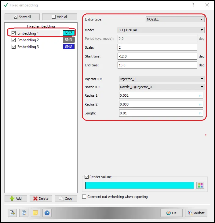
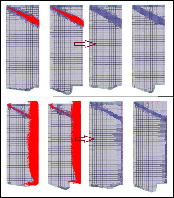
We can see, how the mesh is refining because of the fixed embedding applied for the spray nozzle.
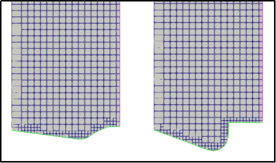
Fixed Embedding for the piston head surface:-
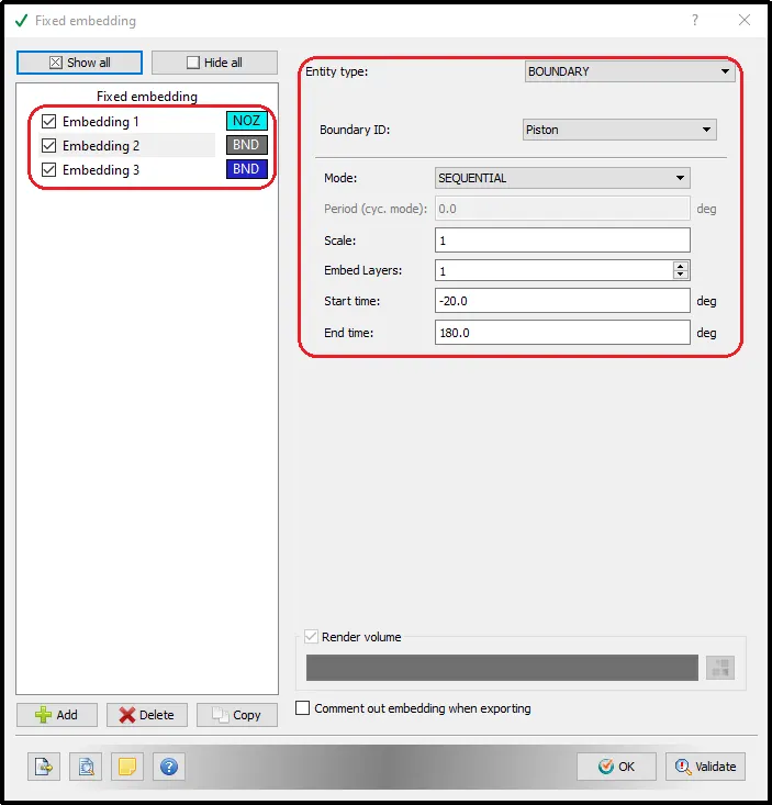
The following picture shows the fixed embedding for the piston wall.
For Cylinder head boundary:-
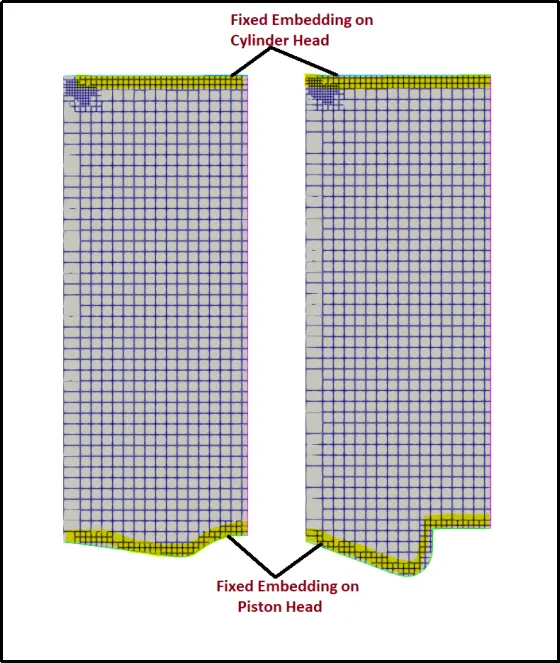
The below picture shows the fixed embedding of the cylinder head wall and piston head wall.
Final Mesh Generation animation:-
Output files parameters:-
The 3D output file will be generated after every 2 degrees of rotation of the crankshaft.
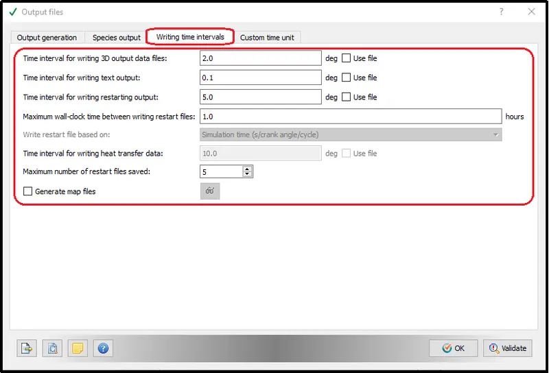
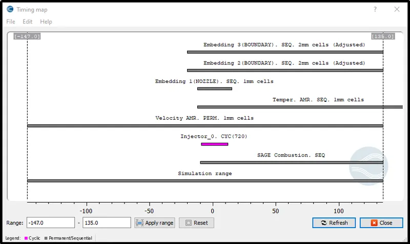
Timing Map:-
The timing map is like a pathway that lays out all simulation timing details into something like a process chart which displays specified timing for the specific process. This map is important to validate that the overall setup is correct.
Results:-
Velocity Variation throughout the process:-
Pressure variation:-
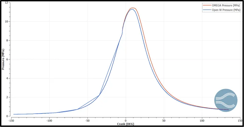
The following chart exhibits the pressure variation inside the combustion chamber during the compression and expansion process. The stroke where the combustion starting, generating extremely high pressure. This is where the engine power is generated.
The peak pressure is 11.53MPa and 11.25 Mpa for Open-w and Omega type of piston, respectively.
Pressure generation with both piston-type is nearly the same till the compression stroke but as the diesel starts to burn it gives us the very slight difference of 2.48%. There is also a slight delay observed in omega piston pressure rise and drop.
Temperature Variation:-
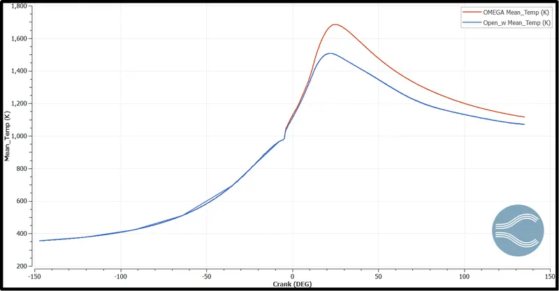
A glips over graphs gives a clear understanding of the timing of peak temperature that the highest mean temperature is obtaining at the expansion stroke.
With the following pattern, it is clear that the Omega type piston achieving higher temperature as compare to the Open-w piston.
The above notion leads to the conclusion that fuel combustion is way more efficient in Omega-type piston combustion chambers.
Meaning there are higher chances with the combustion chamber having open w piston-type generating and releasing more unburned hydrocarbons into the atmosphere. This point we will further verify while comparing emission parameters of the two simulated results.
Heat Release Rate:
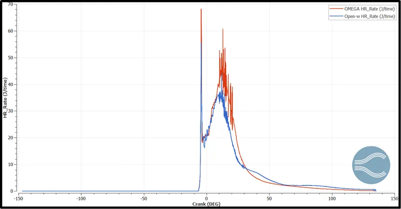
As we observed in the temperature plot, the temperature in the combustion chamber with omega piston is far higher than the open w type combustion volume. Therefore the heat release rate value of the omega is higher.
Now the plot shows a very interesting pattern in which we can observe as the spray stats before the 0-degree angle the diesel liquid dops vaporize and starts to ignite which gives the sudden heat release rate near 0-degree crank angle.
Then after a 0-degree crank angle as the Diesel vapors defuse in the air the heat rate gradually starts to increase towards the pick point and because of expansion, reduction of pressure, it slowly begins to decrease.
Integrated Heat Release Rate:-
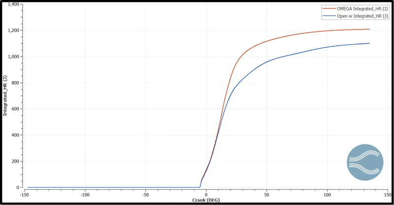
The integrated heat release rate is nothing but the integral form of heat release rate. So, it indicates how much energy is released from combustion at a particular moment. It is observed that for Open-W burning of fuel is not very efficient. Hence it is showing a lower integrated heat release rate as compared to omega. In the experiment, we have injected the same amount of fuel for both cases, and by examination of the result, we can notice energy output of the open-w type piston is far lower than the omega.
Gaseous Fuel Mass:-
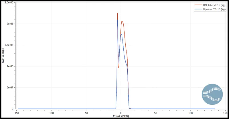
For the Omega piston, a larger amount of gaseous fuel is present which is burnt lately. Hence, the temperature increase will be lower throughout the cycle rather than a sudden increase. With the injection of the gaseous fuel, there is a steep increase in Omega piston gaseous fuel intake which is because of the design. There is significant penetration length in the omega w piston design which as a result allows it to vaporize in the high temperature whereas a lot of fuel impingement occurs in the open-W piston, as a result, the high vapor is not formed, yet as observed the fuel combustion takes place in the end due to high temperature. Another advantage of omega type design is the swirl motion it creates as observed from the above-attached animation of mesh refinement - velocity in Grid control, The circular swirl helps again in vapourization of fuel which leads to higher burning in Omega piston design than in open-W.
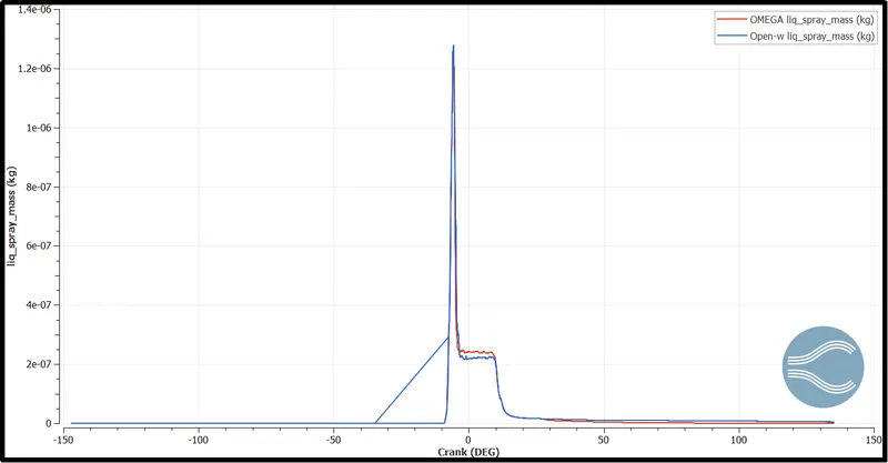
From the observation, it is clear that after the injection of fuel for the Open-W piston the liquid parcels do not evaporate quickly which can be observed in the animation as well. Due to delays in the evaporation, the efficiency and the Torque produced with the open-w piston is lower compare to the Omega Piston.
Emission characterization:-
NOx Emissions:-
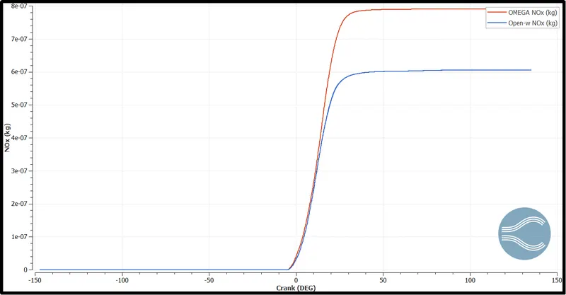
With the higher temperature in the Omega piston and higher heat release, the NOx is significantly higher here than open W. Diesel fuels contain more nitrogen than gasoline and hence they produce higher Nox. The below graph is generated by Zeldovich Nox Model. NOx production is low in OpenW however soot is higher. The critical time is when burned gas temperatures are at a maximum i.e between, the start of combustion and after a short while of the attainment of peak cylinder pressure.
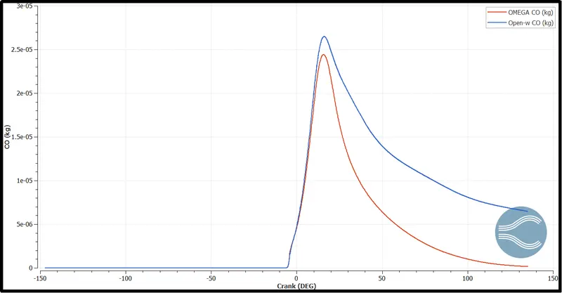
CO Emissions:-
Generally, the formation of carbon monoxide is because of incomplete combustion and the improper mixture of air and fuel. Here combustion volume with open-w piston has improper mixing of fuel-air mixture which decreases the reaction rate. Hence the lower temperature is observed in the open-w piston and that's results in improper flame propagation and incomplete combustion of the fuel.
Open-W has higher CO emissions due to the presence of unburnt fuel which is shown in the animation due to fuel impingement in the Open-W piston. A higher peak is obtained by the omega piston however it decreases right after combustion, but there is a significant delay in the Open-W piston engine as the fuel remains unburnt for a while.
Therefore, the large amount of carbon monoxide is formed even with higher values during combustion, the overall output values have decreased drastically for the Omega Piston.
Hiroy Soot:-
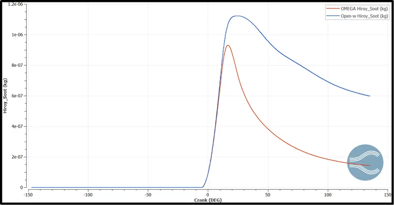
The mass of soot calculated using the Hiroyasu model is shown below. What we can observe is as soon as the combustion process starts soot starts to accumulate in small quantity then it reaches its peak value when the pressure is maximum then dissolves and averages and becomes steady attaining a certain value. These are generated in the fuel-rich zones within the cylinder during combustion & come out as exhaust smoke.
Carbon dioxide (CO2) emission:-
Now for the CO2, the case is inverted. The combustion chamber with omega piston generating higher CO2. Carbon dioxide is from because of the burning of fuel. So, it is the obvious reason that efficient burning of fuel is responsible for the generation of higher CO2 emissions.
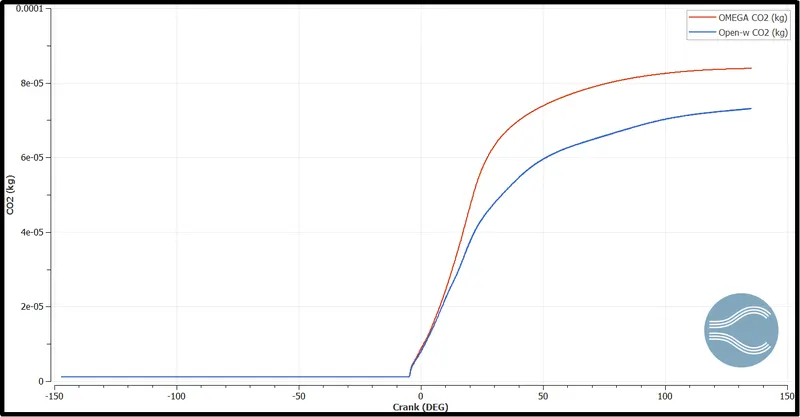
The below animation shows the CO2 generation and variation in both combustion chambers.
Hydrocarbon (HC)-
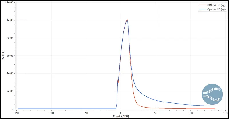
The unburnt Hydro-Carbons result from the Hydro-Carbons present in the fuel escaping from the combustion.
The above-shown animations clearly say that the Open-W piston does not completely combust the air and fuel mixture because of the lower mean temperature inside the cylinder and also the geometry of the piston affects the process.
If we observe this thing with more detail by referring to the below plot, for the Open-W piston the UHC is higher when compared to ‘omega pistons. To achieve a more good combustion process higher cylinder temperature as well as perfect piston design is essential.
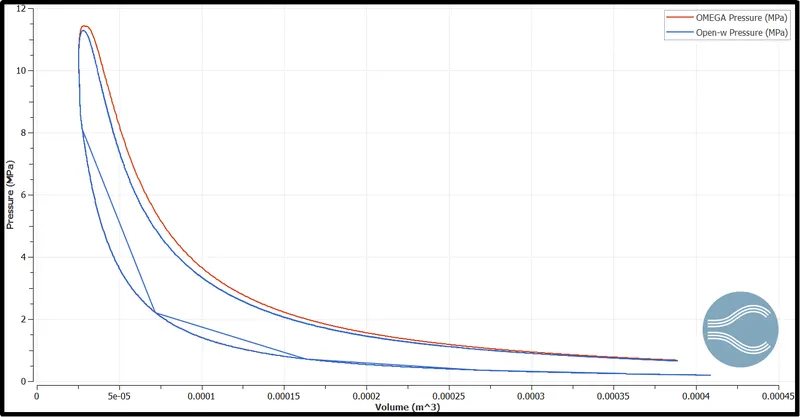
PV Plot:-
For an actual cycle, the shape of the PV diagram is similar to the ideal, but the area (work) enclosed by the PV diagram is always less than the ideal value.
since this simulation is performed only for closed cycle simulation, the motion of intake and exhaust plots are not available.
The diesel engine differs from the gasoline-powered otto cycle, this is because of the highly compressed hot air to ignite the fuel rather than using a spark plug which is the spark ignition.
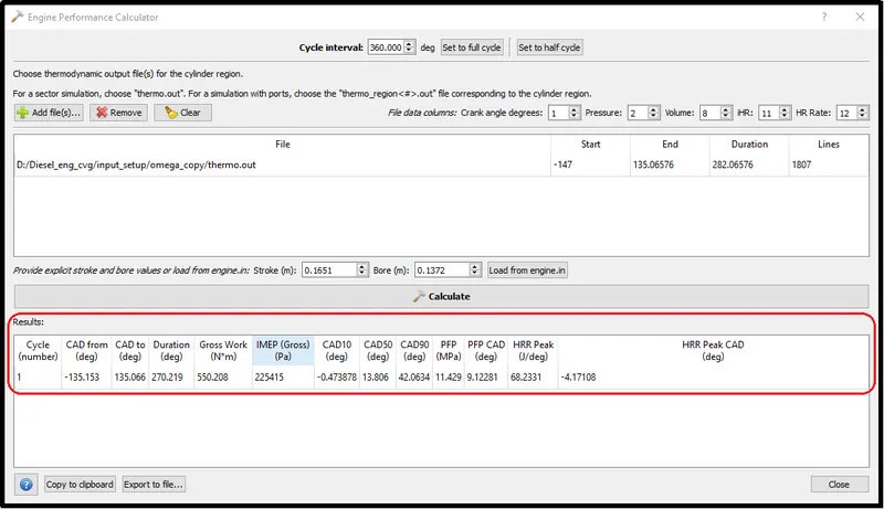
Engine Performance Calculator:-
Combustion chamber with the Omega type piston:-
Combustion chamber with the Open-w type piston:-
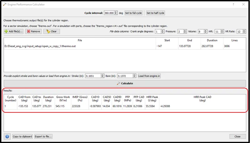
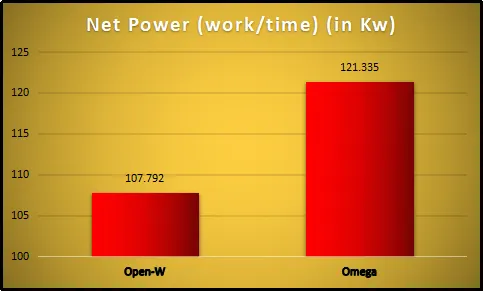
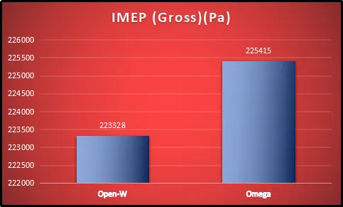
After looking at the combustion performance parameters we can notice a huge difference in the output results of both simulations. Judging based on the charts and facts that were examined earlier one can understand the reason behind it. but before concluding the final points it is vital to compare their indicated mean effective pressure and power output.
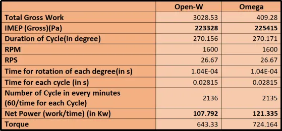
Comparison of Net power:-
It is quite easy to conclude that we are getting maximum power output with the Omega-type piston.
Indicated Mean effective Pressure:-
Similarly, the Indicated Mean effective pressure of the omega piston is higher than the IMEP with Open-w type piston.
Conclusion:-
[1] Upon the observation, we saw fuel automization and vaporization is not effective in the case of the Open-w type of cylinder as the spray of the liquid fuel directly striking the piston surface. On the other hand, Omega piston fuel automization and mixing are effective compare to open-w, and therefore, it provides proper combustion of fuel.
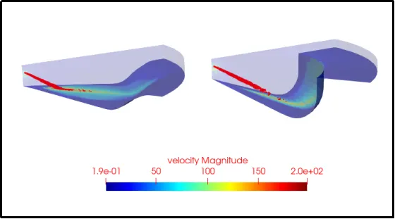
[2] To improve the Open-w piston performance, we can change the angle of injection towards the horizontal direction, so that it will more interact with hot compressed air rather than directly striking on the surface of the piston head.
[3] Clearance Volume is the most important parameter in an IC engine which decides its performance and Fuel consumption. If clearance will be less it will bang the piston, If clearance is more it will pull off the air during suction stroke which creates a problem in compression.
Now, we as Omega pistons have large clearance compare to open-w, which will reduce the volumetric efficiency of the engine which again affects the performance of the engine.
[4] Because of the higher temperature achieved with Omega type piston, the soot, and NOx emissions in the combustion chamber with omega piston are more compare to Open-w.
[5] On the other hand, unburned fuel due to fuel impingement in the combustion chamber with open-w type position, its have CO and HC emissions are higher.
[6] For the lower emission, we require proper mixing and complete combustion which will also improve the power output of the engine. Hence considering this parameter Omega piston providing better results in this particular simulation. But we also know it has a high clearance ratio means lower volumetric efficiency which affects the performance.
[7] If we set the proper angle to the injector for the combustion chamber of an open-w type piston, it will give us a better air-fuel mixture so complete combustion which will lead to better performance of the engine. additionally, open w provides less clearance volume, therefore, it can provide more volumetric efficiency.
References:-
[1]Fuel Injectors and Sprays - https://convergecfd.com/applications/fuel-injectors-and-sprays
[2] Reduction in Compression Ratio and Increase in Clearance Volume with Coating Thickness - https://www.researchgate.net/figure/Reduction-in-Compression-Ratio-and-Increase-in-Clearance-Volume-with-Coating-Thickness_fig2_319606166
[3] The Study on the Effect of the Piston Shapes through Biodiesel Mixture Combustion in Diesel Engine - https://www.e3s-conferences.org/articles/e3sconf/pdf/2018/28/e3sconf_icaeer2018_03022.pdfhttps://www.osti.gov/servlets/purl/1344713
[4] Methodology to reduce diesel engine pollutant emissions-https://www.researchgate.net/publication/338479187_Methodology_to_reduce_diesel_engine_pollutant_emissions