Week 11: Project 2 - Emission characterization on a CAT3410 engine
Aim: To run the IC engine simulation for two pistons and compare the emission characteristics
Case setup preparation:
Engine sector data:
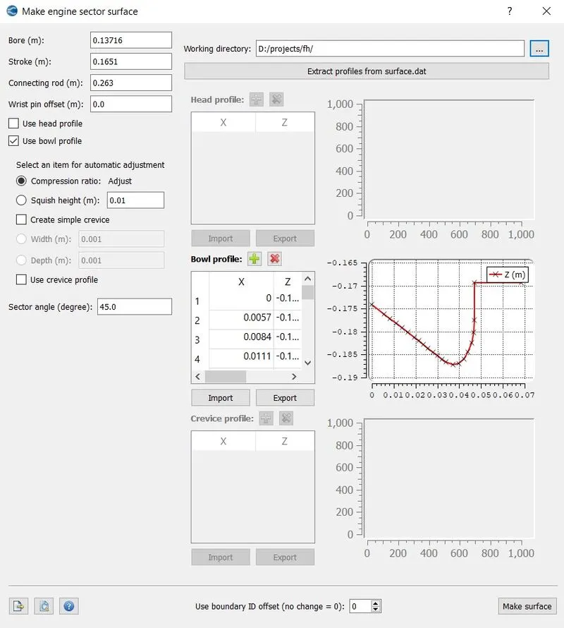
The iput data like bore, stroke and connecting rod is provided then the bowl profile is imported. Thus completing the preparation of design make surface option is selected to create the geometry.
Omega Geometry:
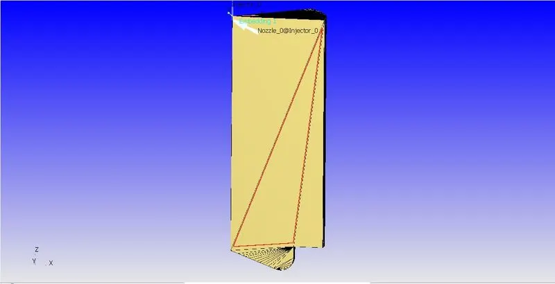
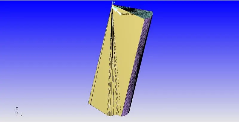
Open_W geometry:
Application type:
After the completion of design, The case setup is started and followed.
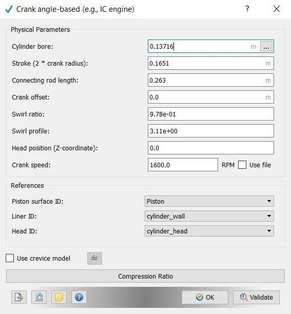
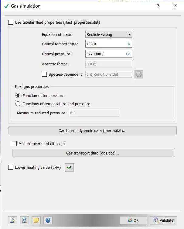
Gas simulation:
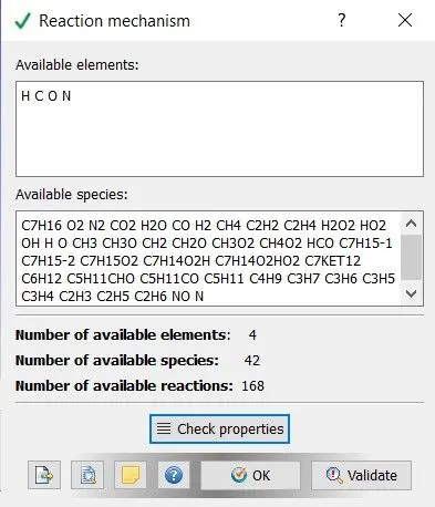
Reaction Mechanism:
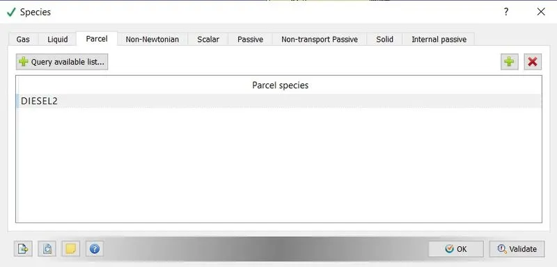
Species:
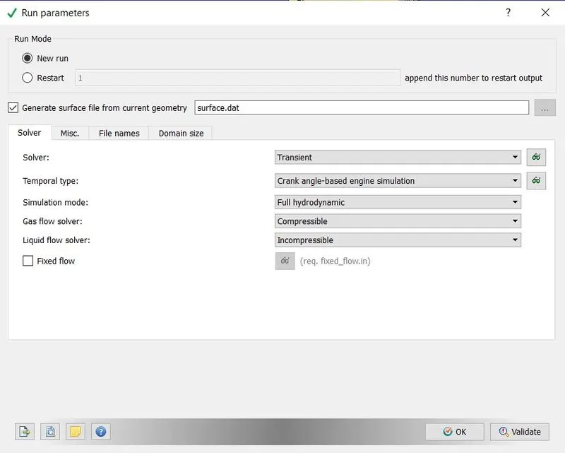
Run parameters:
Simulation time parameters:
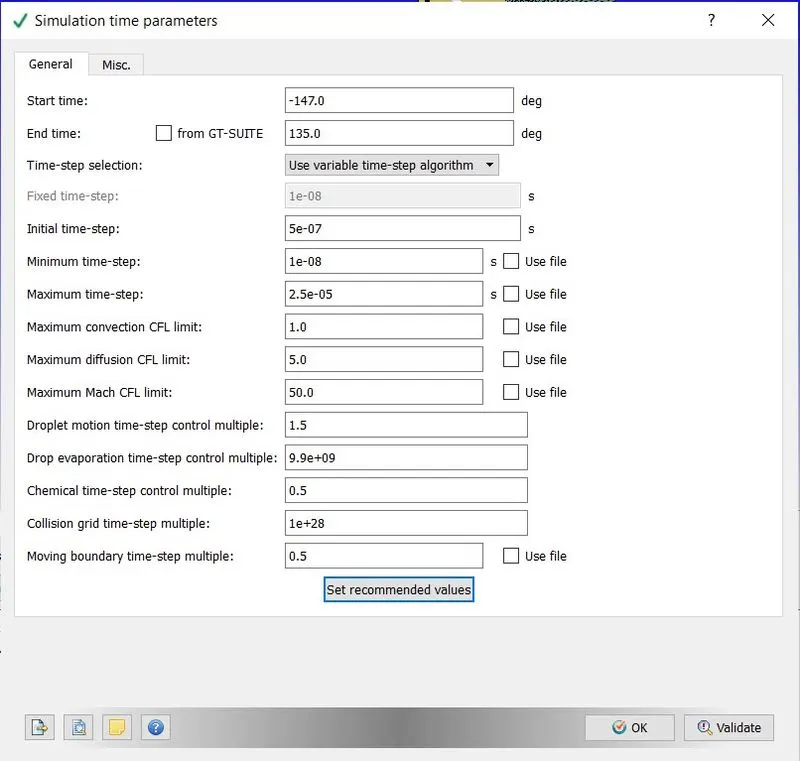
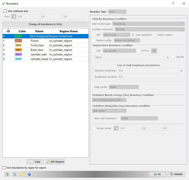
Boundary condition:
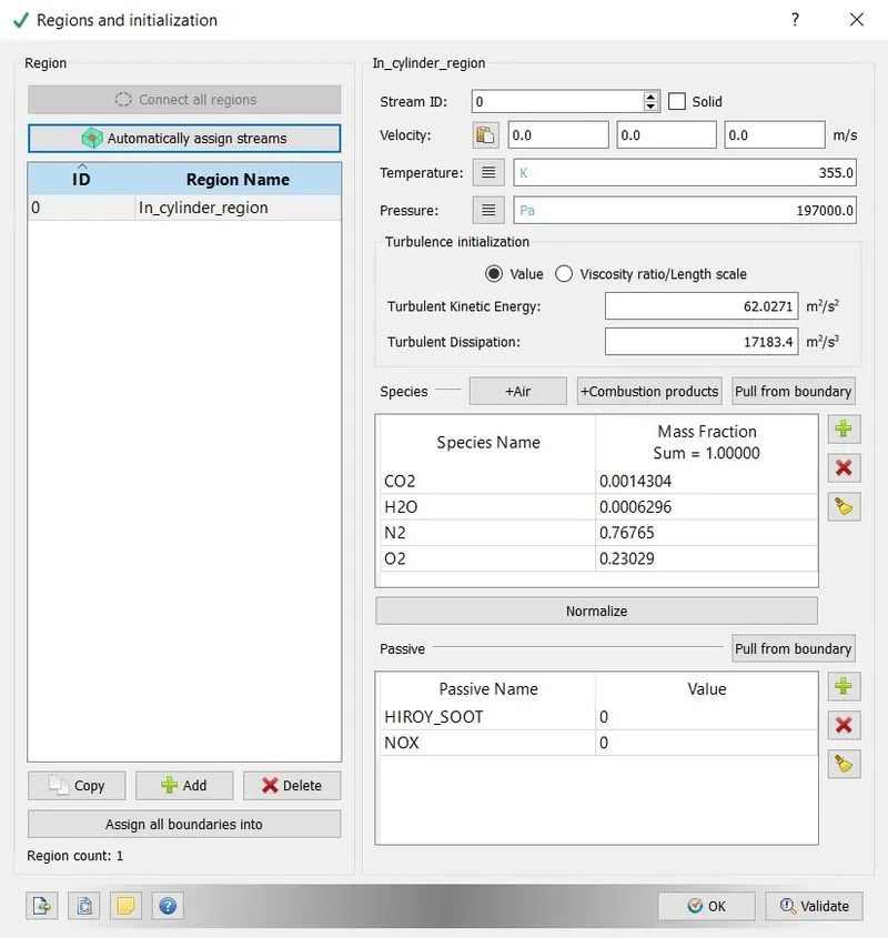
Regions:
Spray Modeling:
Sprays belong to a specific type of two-phase flows which are characterized by a dominating direction of motion and involve liquid phase in a discrete form of droplets and ligaments and the gas phase as the continuum. Regardless of applications, sprays are the results of high pressure-driven liquid jets injected through one or several injector nozzle orifices into a combustion chamber. The jet atomizes into different liquid fragments, and, finally, into droplets, which evaporate producing vapor which mixes with oxidizer (air) forming a combustible mixture which ignites due to the presence of the additional energy supply or due to increased pressure and temperature in the piston compression ignited engines, and, thus, initiates the combustion process. Combustion process proceeds in a form of a diffusion flame, but two phase effects significantly influence the spray flame structure, even in the case of relatively thin sprays when the volume fraction occupied by the liquid is small compared with that of the gas. From one side for systems of practical interest, even if experimental measurements are possible, they are not representing well controlled data from which all effects on the individual variables could be extracted. From the other side, numerous results of the classical studies of isolated droplets are available and still waiting to be used. In a diesel engine, liquid fuel is injected into the combustion chamber near the end of the compression stroke. Following injection, the fuel undergoes atomization and vaporization processes, followed by fuel-air mixing, ignition and combustion processes. It is well known that the primary breakup of the fuel influences downstream processes such as mixing, ignition combustion, etc.
Primary fuel atomization is induced by aerodynamics in the near-nozzle region, as well as cavitation and turbulence from the injector nozzle. The breakup models that are currently used in diesel engine simulations generally consider aerodynamically induced breakup using the Kelvin-Helmholtz (KH) instability model, but do not account for in-nozzle flow effects.
Argonne transportation engineers, in collaboration with Convergent Science, Inc., have developed a computational methodology that results in grid-convergent behavior. Specifically, the following items are critical to grid-convergence:
- Adaptive mesh resolution
- Fully-implicit momentum coupling
- Improved liquid gas coupling
- Increasing the number of injected spray parcels
- Inject parcels in a radius instead of point source
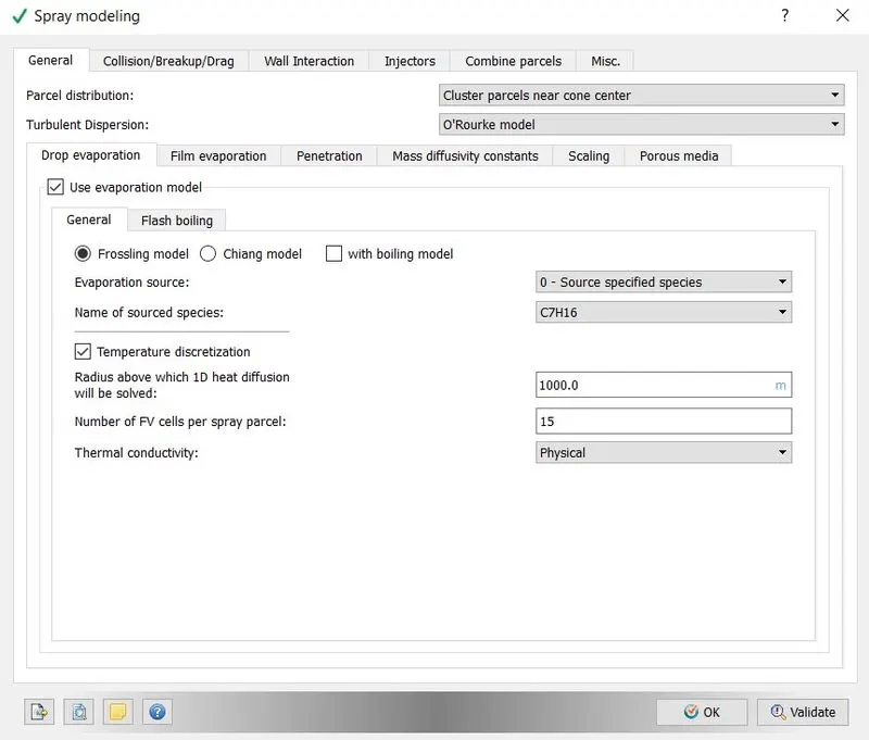
Injector:
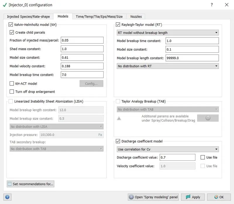
Model:
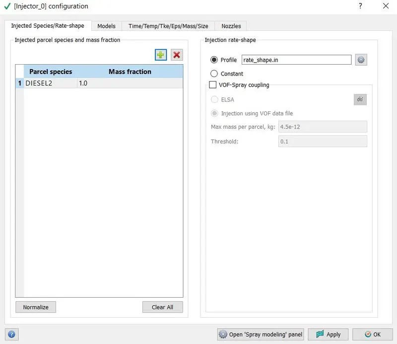
Species:
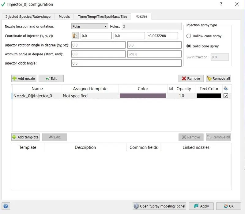
Nozzle data:
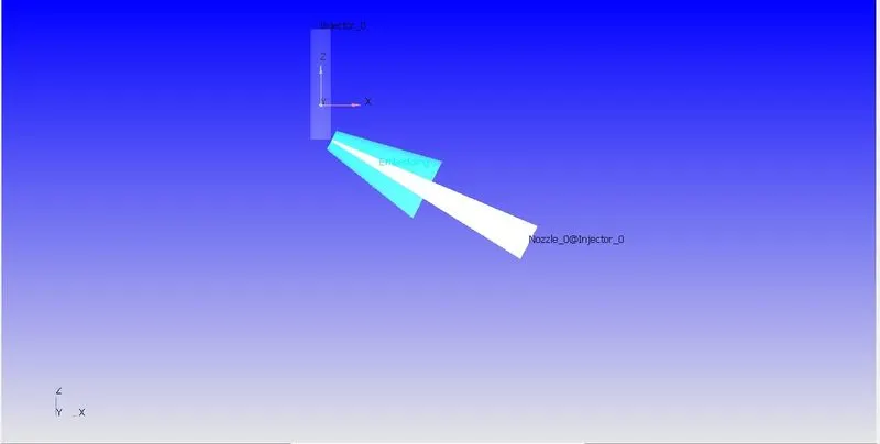
Nozzle Geometry:
Combustion Modeling:
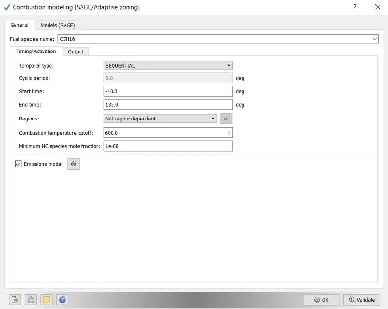
Turbulance Modeling:
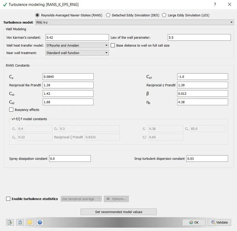
Base grid:
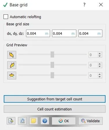
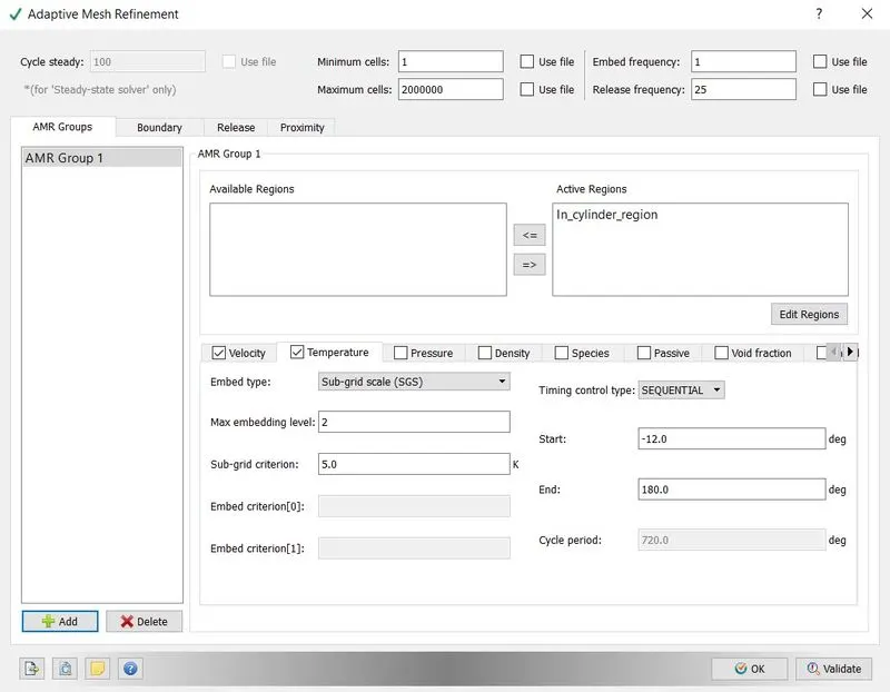
Adaptinve Mesh refinement:
In numerical analysis, adaptive mesh refinement (AMR) is a method of adapting the accuracy of a solution within certain sensitive or turbulent regions of simulation, dynamically and during the time the solution is being calculated. When solutions are calculated numerically, they are often limited to pre-determined quantified grids as in the Cartesian plane which constitute the computational grid, or 'mesh'. Many problems in numerical analysis, however, do not require a uniform precision in the numerical grids used for graph plotting or computational simulation, and would be better suited if specific areas of graphs which needed precision could be refined in quantification only in the regions requiring the added precision. Adaptive mesh refinement provides such a dynamic programming environment for adapting the precision of the numerical computation based on the requirements of a computation problem in specific areas of multi-dimensional graphs which need precision while leaving the other regions of the multi-dimensional graphs at lower levels of precision and resolution.
This dynamic technique of adapting computation precision to specific requirements has been accredited to Marsha Berger, Joseph Oliger, and Phillip Colella who developed an algorithm for dynamic gridding called local adaptive mesh refinement. The use of AMR has since then proved of broad use and has been used in studying turbulence problems in hydrodynamics as well as in the study of large scale structures in astrophysics as in the Bolshoi Cosmological Simulation.
Velocity:
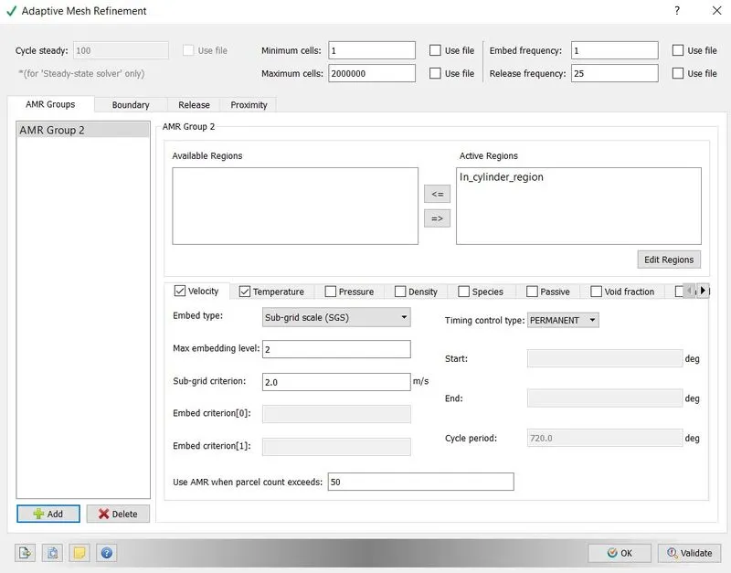
Temeperature:
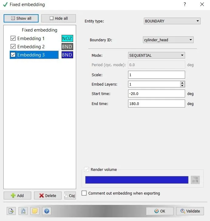
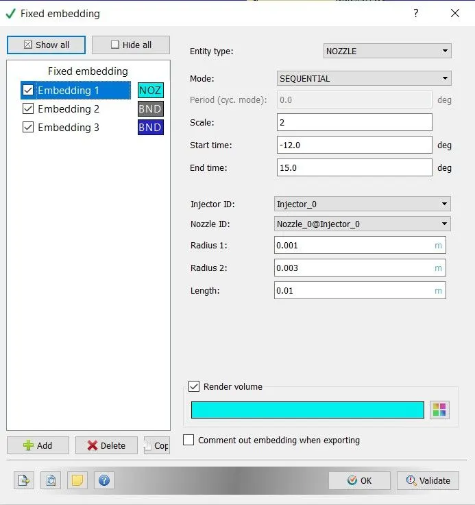
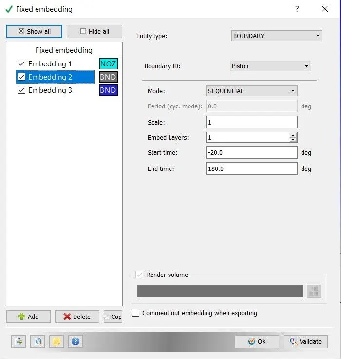
Fixed embedding:
Cylinder:
Nozzle:
Piston:
Result:
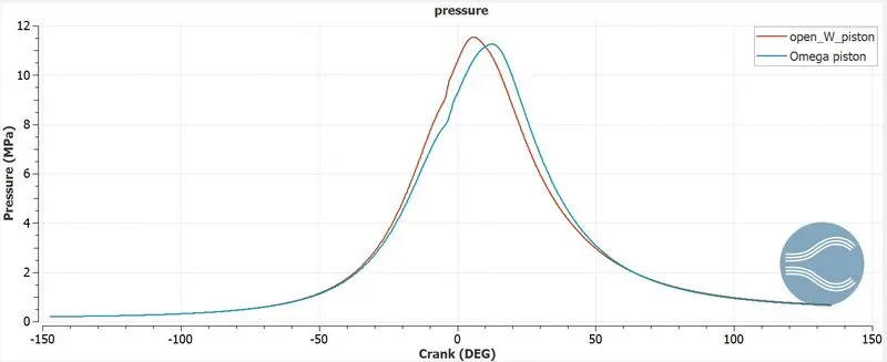
Pressure plot:
Temperature plot:
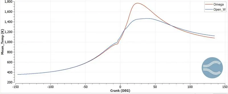
Omega piston tends provide high temperature due to the spray mixture vaporiouzation throught the chamber before the combustion without getting disturbed by wall arounds and piston wall which significantly affect the combustion and emssion.
Volume plot:
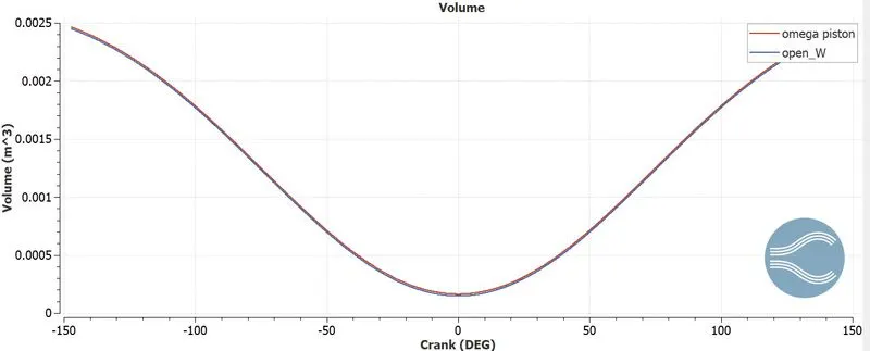
The volume swept by both the piston are almost same with very small deviation which affects the compression ratio in very small value that can be neglected.
PV plot:
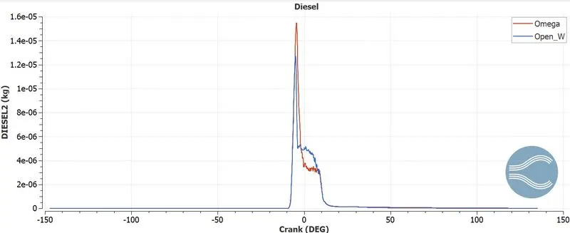
Diesel flow plot:
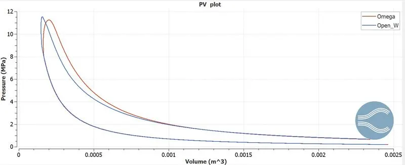
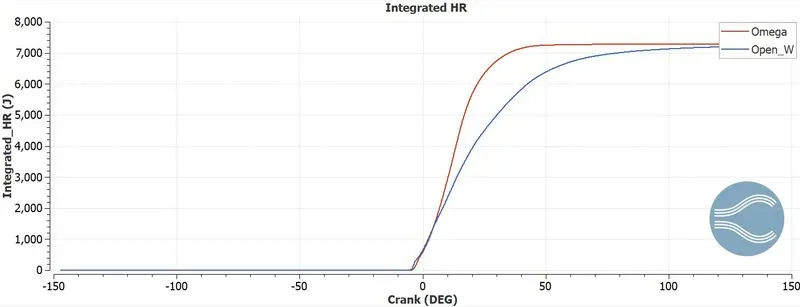
The Omega piston has diesel flow freely in the combustion chamber due the bowl shape of omega piston with can seen clearly in velocity and fuel spray video. This spray flow leads to high temperature and energy output which effective affect the emission characteristics.
Integrated HR plot:
Emmission
CO plot:
CO2 plot:
NOx plot:
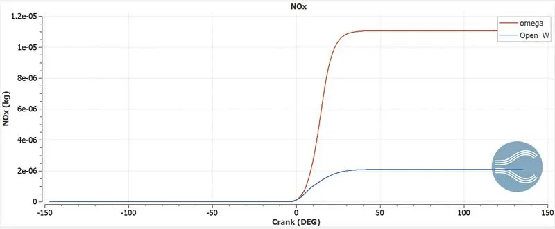
NOx animation:
SOOT plot:
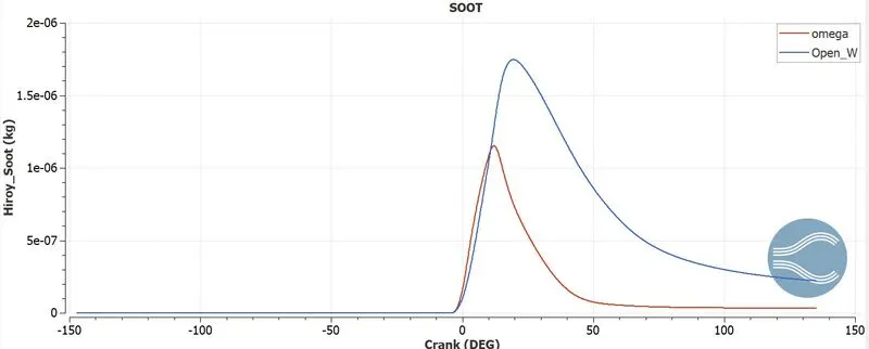
Soot animation:
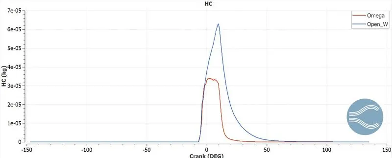
HC plot:
Mesh animation:
Omega piston:
Open_W piston:
Temperature animation:
Omega piston:
Open_W piston:
Velocity animation
Omega piston:
Open_W piston:
fuel Spray cut-plane animation:
Omega piston:
Open_W piston:
Fuel spray 3D animation:
Omega piston:
Open_W piston:
Calculation:
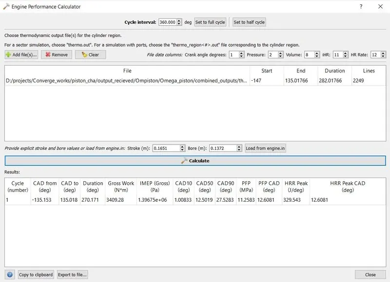
Enigine performance
Omega piston:
Open_W piston:
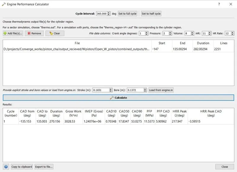
Power and Torque:
Formulas:
Total time = Time per degree * Cumbustion duration
Power = Work done / Time taken
Torque = (Power*60)/(2*pi*N)
| Omega piston | Open_W piston | |
| Work done (j) | 3409.28 | 3028.53 |
| Cumbustion duration(deg) | 270.171 | 270.156 |
| RPM | 1600 | 1600 |
| Time per degree | 0.0001047 | 0.0001047 |
| Total time of cumbustion(s) | 0.028142 | 0.028285 |
| Power(w) | 121145.674 | 107070.685 |
| Torque | 723.03 | 639.03 |
| IMEP | 1.3967e+6 | 1.24076e+6 |
Inference:
- From the simulation of IC engine wih two different piston profile, show the significance of the piston.
- From the simulation results, the Omega piston tesnd to provide better results than Open_W piston.
- The Omega piston provide more Power, Torque and high energy output.
- This tends to complete the combustion avoiding the exhaust to have unburnt hydrocarbons and soot.
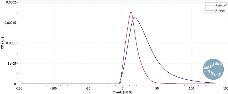
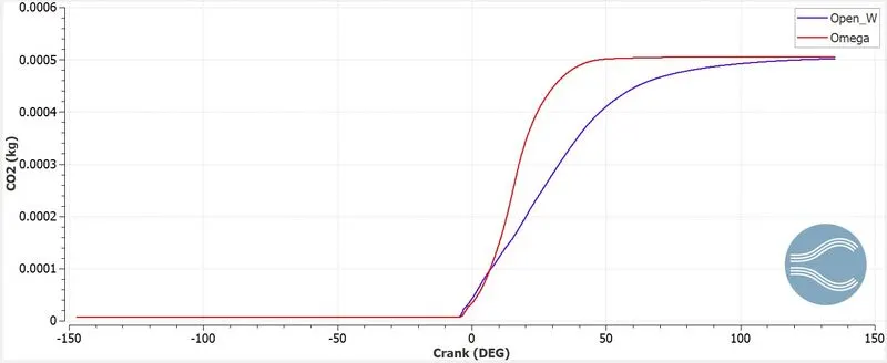
- Yet the High temprature, in cumbustion leads to high output of CO2, CO and NOx in emission.
- The Main reason of this situation is Omega piston lets the fule spray to spread and vapourise te fuel better
- Whereas in Open_W, the fuel sprayed is swept over the piston as liquid particles affecting the completion of cumbustion.