week-11 Joint creation and Demonstration
AIM:
To create spherical, revolute, cylindrical, and translational joints between two rigid bodies and two deformable bodies using LSDYNA.
PROCEDURE:
REVOLUTE JOINT:
A revolute joint is a one-degree of freedom used frequently in mechanisms and machines.The joint constrains the motion of two bodies to pure rotation along a common axis. The joint does not allow translation, or sliding linear motion, a constraint not shown in the diagram. Almost all assemblies of multiple moving bodies include revolute joints in their designs. Revolute joints are used in numerous applications such as door hinges, mechanisms, and other uni-axial rotation devices.
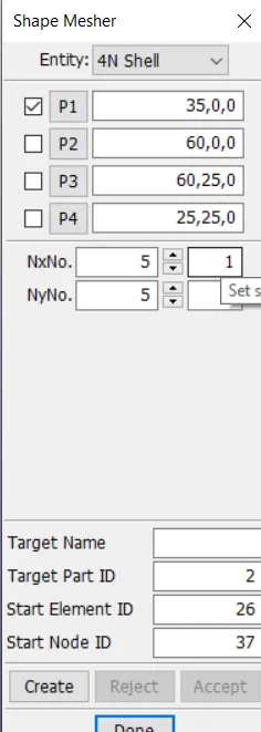
create the model using element and mesher -> shape mesher
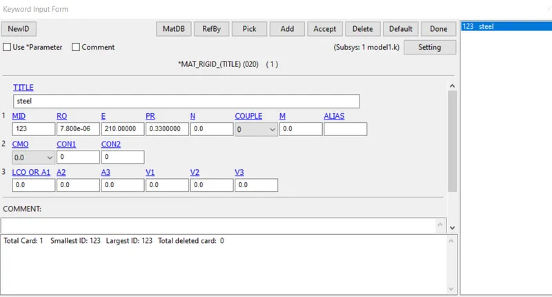
create the material card using the rigid material_020 and import the properties of steel
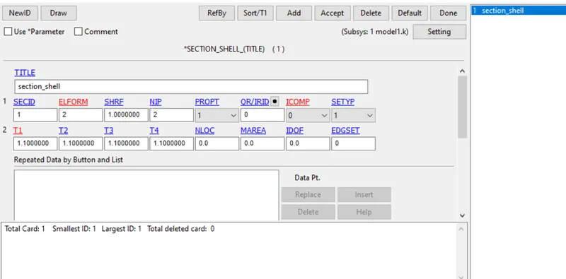
create the section card using elform 2 and set the thickness of 1.2mm.
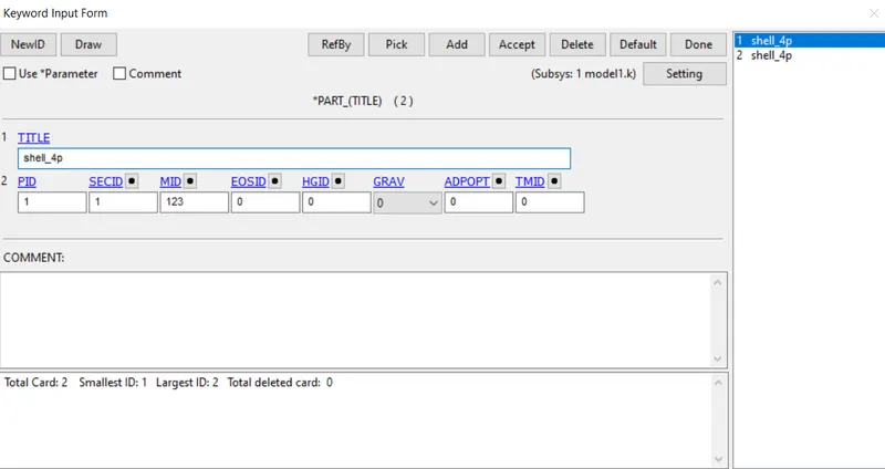
define the part using the material and section card created.
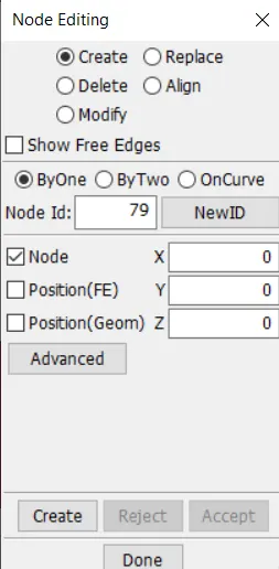
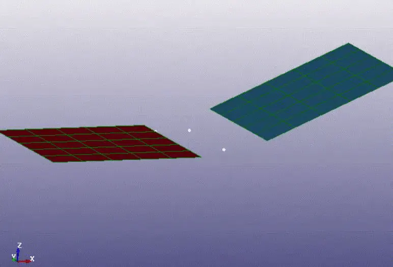
create two pairs of center nodes between two plates using node editing option.
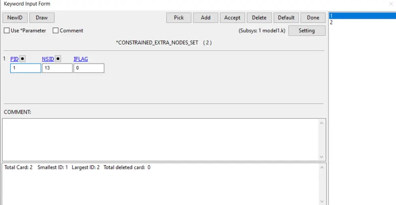
use constrained_ extra_nodes_set and pair the node set created with the respective property id
define the constrains and set the free plate to move in the z translational by setting the dof free in z axis, in the prescribed motion set.
set the control cards such as contrll_implicit_auto, control_implicit_general, control_termination, control_timestep.
set the database and define the d3plot with 0.1ms as the total run time is 1 second.
at last set the control_joint_revollute for the motion to occur.
CYLINDRICAL JOINT:
A cylindrical joint is a two DOF's used in mechanisms. Cylindrical joints provide single-axis sliding function as well as a single axis rotation, providing a way for two rigid bodies to translate and rotate freely. This can be pictured by an unsecured axle mounted on a chassis, as it may freely rotate and translate.
create the model using element and mesher -> shape mesher and select cylindrical shell.
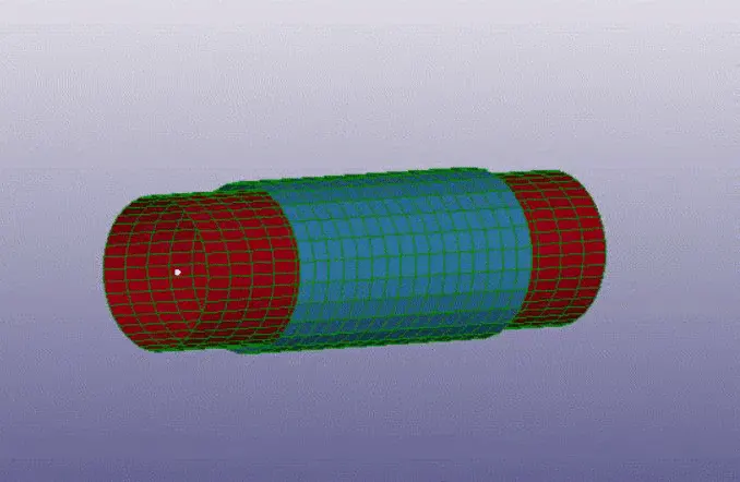
two different cylinders with different radius and lengths are created, coincideing ecah other.
create the material card using the rigid material_020 and import the properties of steel
create the section card using elform 2 and set the thickness
define the part using the material and section card created.
create two pairs of center nodes between two cylinders using node editing option.
use constrained_ extra_nodes_set and pair the node set created with the respective property id
define the constrains and set the cylinder to rotate in the x aixs by setting the dof free in x axis, in the prescribed motion set.
set the control cards such as contrll_implicit_auto, control_implicit_general, control_termination, control_timestep.
at last set the control_joint_cylinder for the motion to occur.
SPHERICAL JOINT:
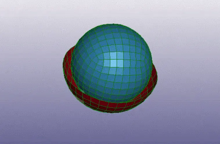
A spherical rolling joint is a high-precision ball joint consisting of a spherical outer and inner race separated by ball bearings. The ball bearings are housed in a spherical retainer and roll along both the inner and outer surfaces.
create the model using element and mesher -> shape mesher and select spherical shell.
one half of the outer sphere is deleted inorder to form a semi sphere.
create the material card using the rigid material_020 and import the properties of steel
create the section card using elform 2 and set the thickness
define the part using the material and section card created.
create two pairs of center nodes for both the spheres using node editing option.
use constrained_ extra_nodes_set and pair the node set created with the respective property id
define the constrains and set the sphere to rotate in the x aixs by setting the dof free in x axis, in the prescribed motion set.
all the dof's the semi sphere is arrested.
set the control cards such as contrll_implicit_auto, control_implicit_general, control_termination, control_timestep.
at last set the control_joint_spherical for the motion to occur.
TRANSLATIONAL JOINT:
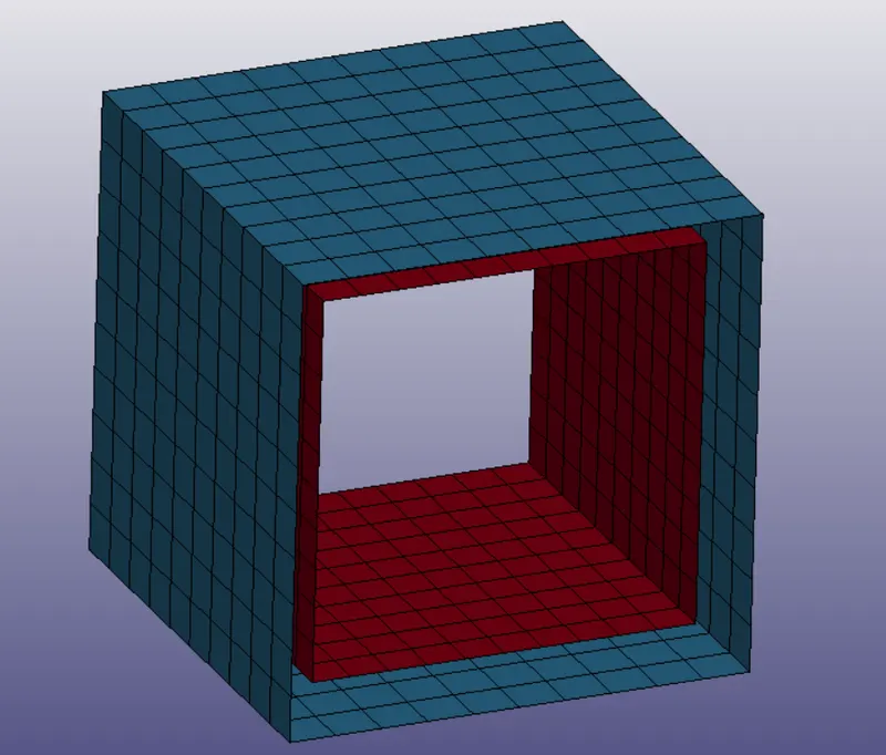
A translational clearance joint does not constrain any degree of freedom of the mechanical system but it imposes some restrictions on the slider motion inside the guide limits. When the slider reaches the guide surfaces, an impact occurs and the dynamic response of the joint is modeled by contact-impact forces.
create the model using element and mesher -> shape mesher and select box shell.
two different boxes with different sizes conciding each other are created.
create the material card using the rigid material_020 and import the properties of steel
create the section card using elform 2 and set the thickness
define the part using the material and section card created.
create two pairs of center nodes between two boxes using node editing option.
use constrained_ extra_nodes_set and pair the node set created with the respective property id
define the constrains and set the free plate to move in the x translational by setting the dof free in z axis, in the prescribed motion set.
all the dof's the outer box shell is arrested.
set the control cards such as contrll_implicit_auto, control_implicit_general, control_termination, control_timestep.
at last set the control_joint_translational for the motion to occur.
RESULTS:
Joints such as spherical, revolute, cylindrical, and translational joints between two rigid bodies and two deformable bodies where created using LSDYNA.