week-11 Joint creation and Demonstration
objective
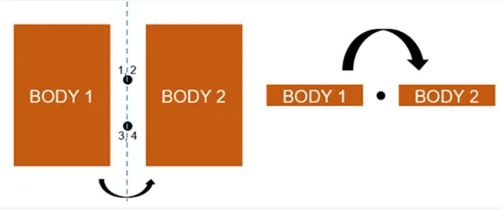
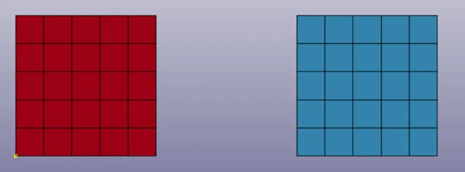
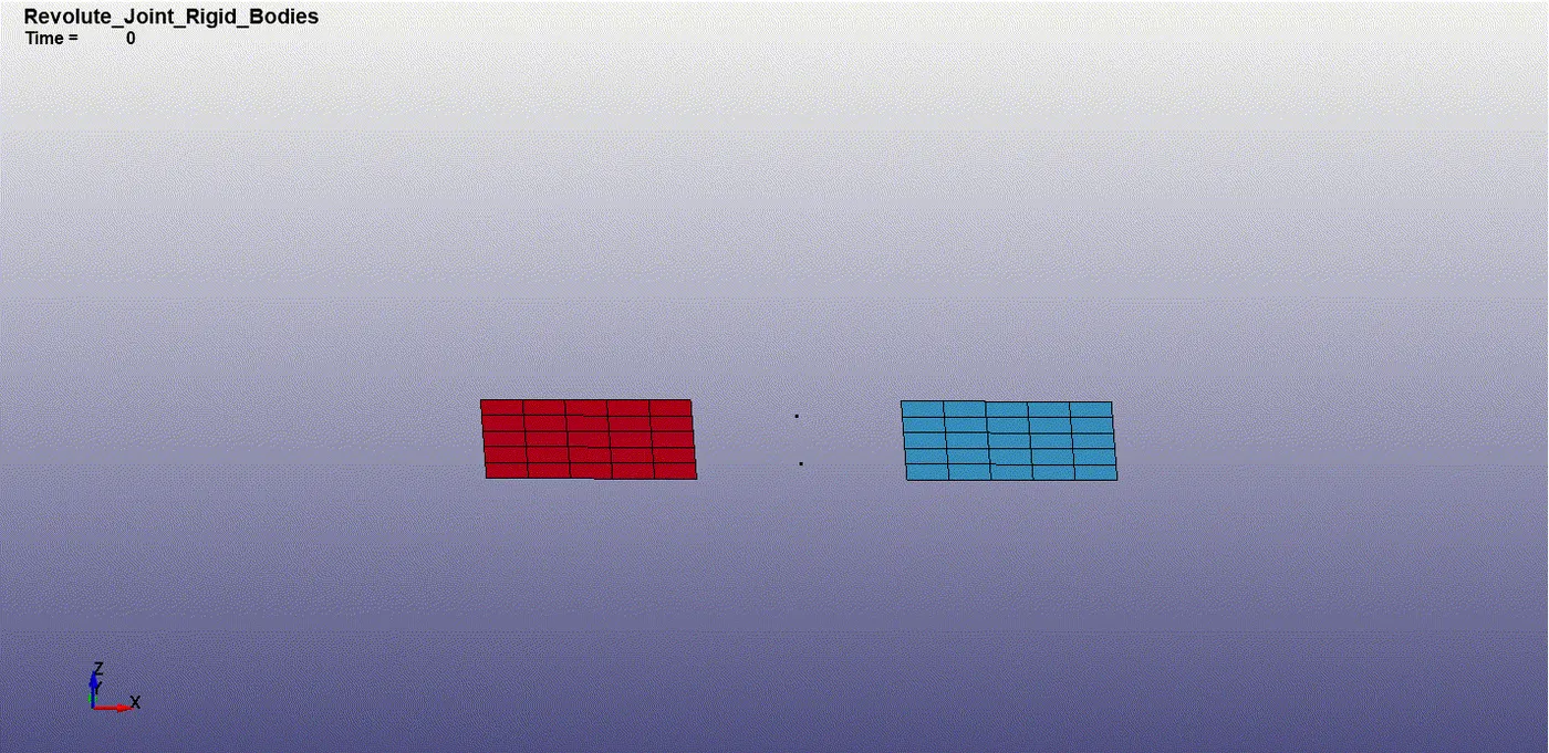
- Open ls-prepost go to mesh > shape mesh > entity :4N shell > create two parts as shown below.
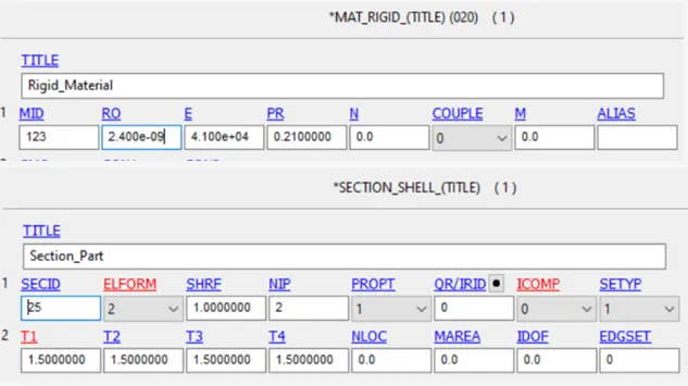
2. The material and section card has to be defined and assigned to the part.
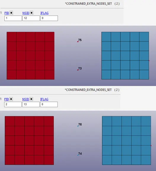
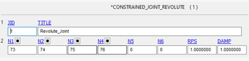
- Go to element tools > node edit > create >four nodes have to be created at the center of entity option. Apair of nodes have to be assigned to the part using * constrained_extra_nodes .
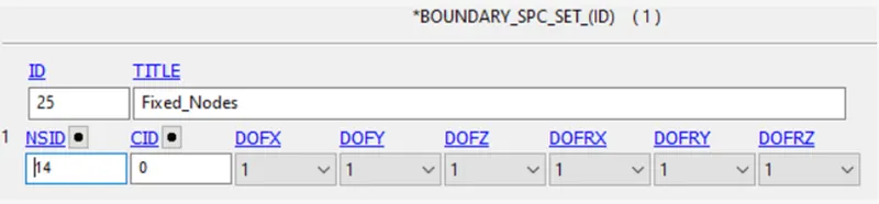
- For applying boundary condtions the following nodes has to be fixed
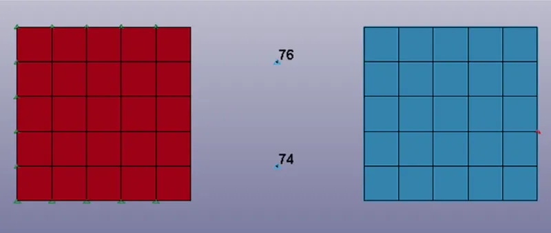
the nodes highlighted color has to be arrested in all DOFs.
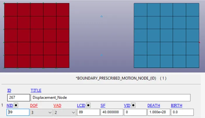
For defining displacement the node highlighted in red has to be selected
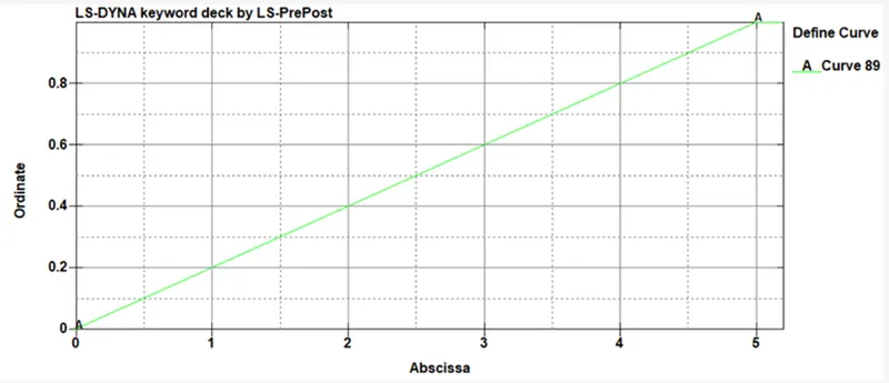
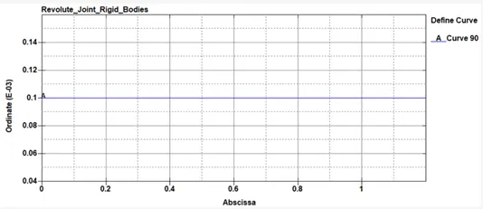
Displacement curve id is shown below.
The control _timestep card has to be defines using LCTM option. The total termination time is defined as 5ms.
cylindrical joint
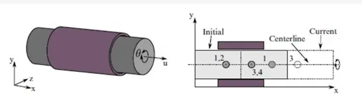
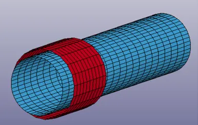
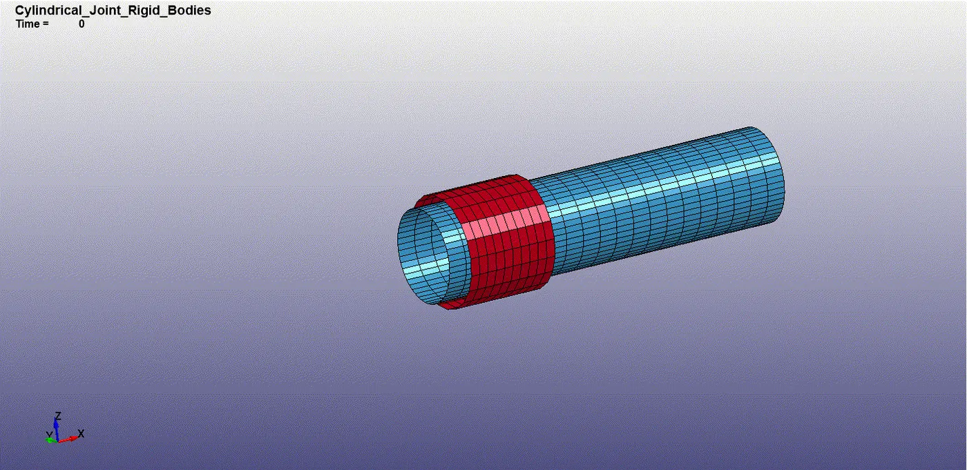
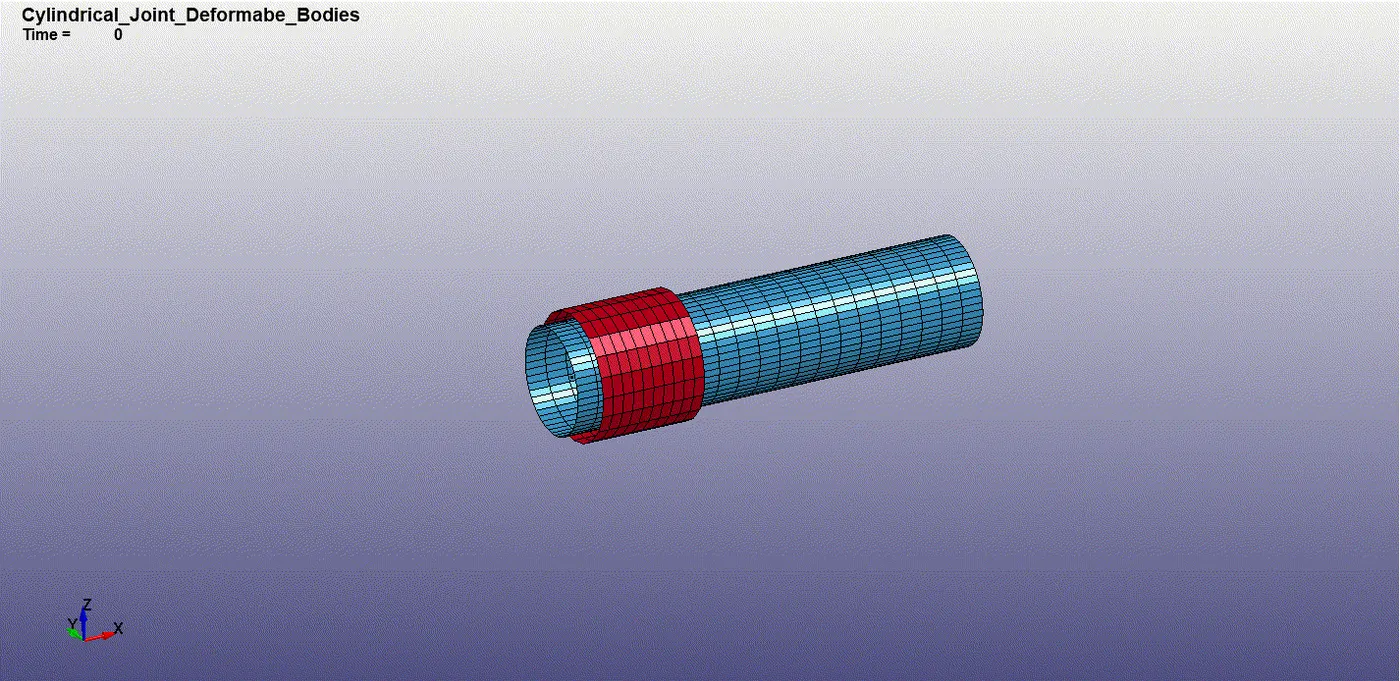
Go to mesh > shape mesh > entity : cylindrical shell > create two parts as shown below. The parts are named appropriately using the keyword manager.
Follow step 3 and 4 as given revolute joint.
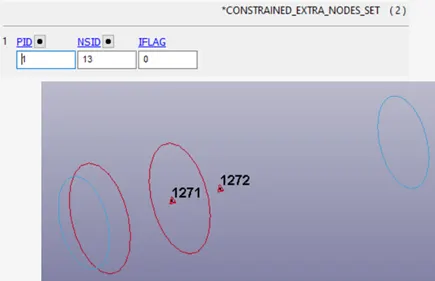
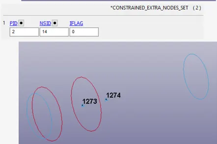
The cylinddriacl joint is defined using the keyword *constrained _joint_cylindrical.
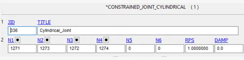
The nodes N1 and N3 must be in rigid body .A the nodes N2 and N4 must be in rigid body B.
the velocity is defined using the keyword *initial_velocity_rogid body.

follow step 8 and 9 as given revolute joint.
Spheriacal joint
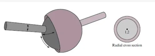
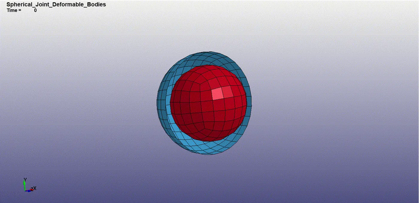
Go to mesh > shape mesh entity : sphere shell create two parts as shown below. Half of the outer spherical shell is deleted. The parts are named appropriately using the keyword manager.
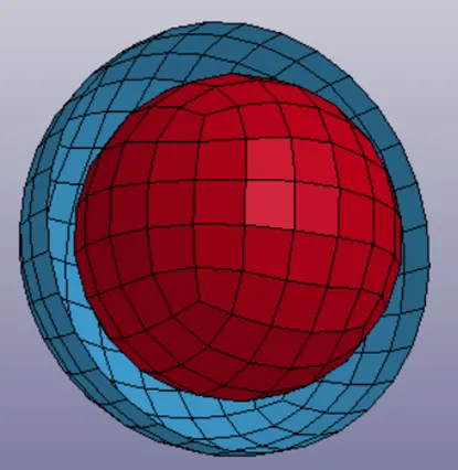
2. Follow steps 3 and 4 as given in the revolution joint.
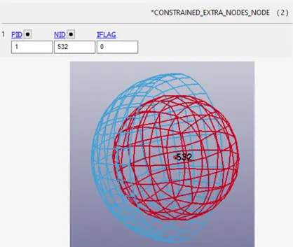
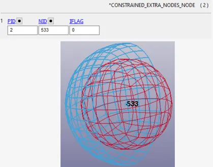
3. The cylindrical joint using keyword *constrained_joint_spherical
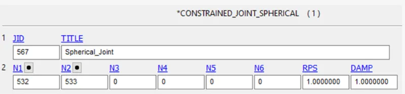
The nodes N1 and N2 must be in rigid bodies A and B respectively.
4. The velocity is defined using the keyword *initial_velocity_rigid_body.

5. Follow step 9 and 10 as given revolute joint.
Translational joint.
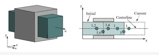
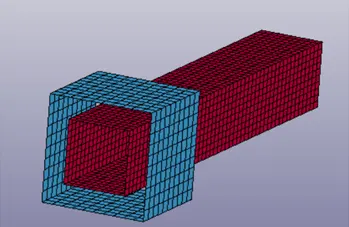
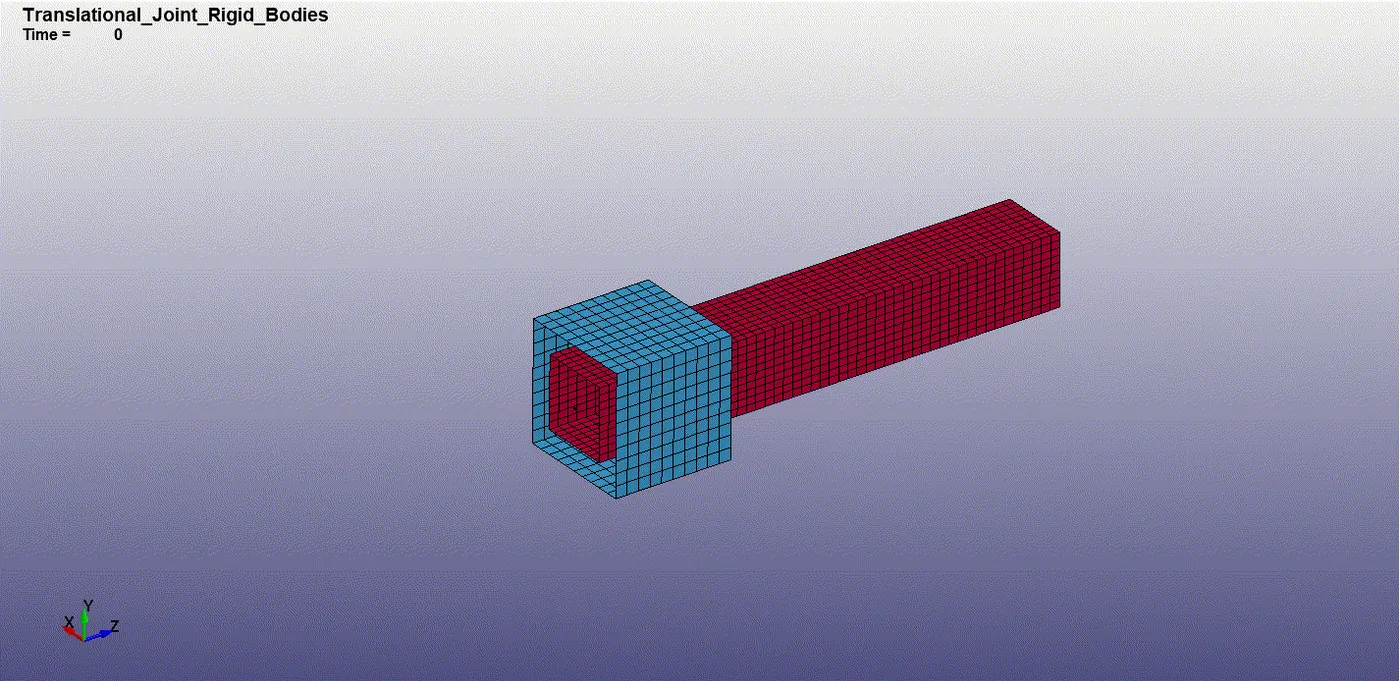
1. Go to mesh shape mesh entity 4N shell create a face go to element generation shell edge drag. Select the edges of the face and drag it along an axis. The final geometry obtained is shown below. Half of the outer spherical shell is deleted.
2. Repeat step 2 as given in the revolute joint.
3. For this joint three pairs of nodes have to be defined. Two pairs of nodes must be coincident and collinear. The third pair of nodes must be in between the other two pairs and slightly displaced from the axis of the other pair of nodes.
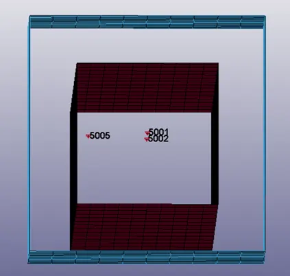
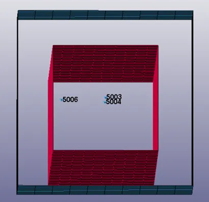
The nodes have to be assigned to the respective part. The nodes highlighted in red and blue indicate the part to which it belongs to.
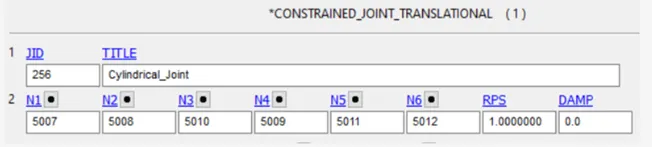
4. The translational joint is defined using * constrained_joint_ translational.
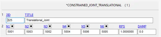
The nodes N1, N3 and N5 must be in rigid body A and node N2, N4 and N6 must be in rigid body B.
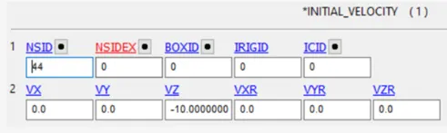
5. The velocity is defined using the keyword *initial_velocity_ rigidbody.

6. Follow steps 9 and 10 as given in the revolute joint.
Revolute joint
cylindrical joint
translational joint
spherical joint
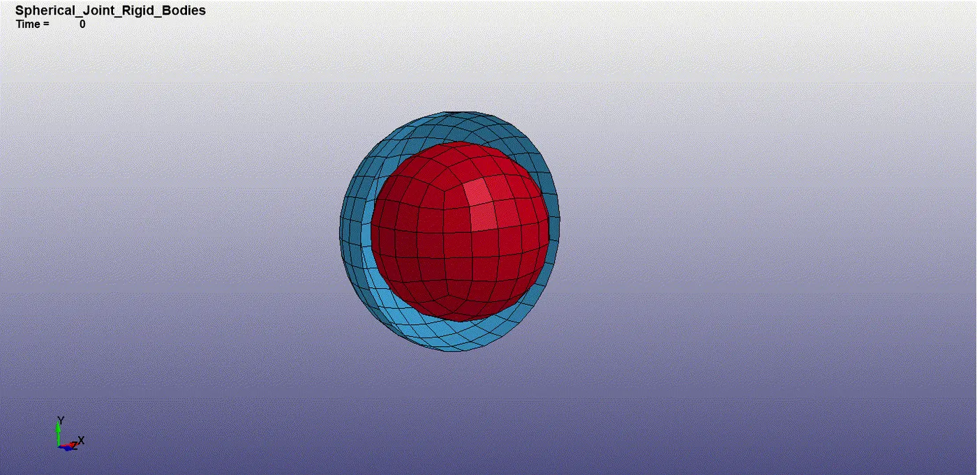
Creating joints between deformable bodies.
Revolute joint
1.Repeat step 1 of the revolute joint of rigid bodies. Rename the created parts using the keyword manager
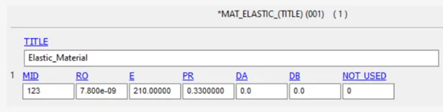
2.The section card is the same as the jointcreation in rigid bodies. The material card is shown below.
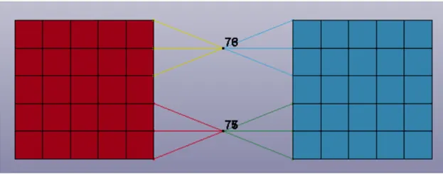
3.Repeat step 4 of the revolute joint of rigid bodies. After this step gobto create entity constrained CNRB. in this option uncheck create P-node option and select the generated node and nodes on the body. Create a CNRB as soon down. Only CNRB nodes has to be created CONSTRAINED extra nodes should not be used.
4.The revolute joint is defined using constrained joint revolute.
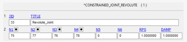
The nodes N1 and N3 must be in rigid body A.The nodes N2 and N4must be in rigid body B..
5.Repeat the steps 5-10 as that of revolute bodies.
Cindrical joint.
1.Follow step 1 as that of cylindrical joint for deformable bodies.
2.The material card is shown below. The section card remains the same for the two cases.

3.Create extra nodes as given in the case of revolute joint for deformable bodies and repeat step 3 of the revolute joint of deformable bodies as given below. Only CNRB nodes has to be created. Constrained extra nodes should not be used
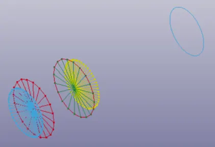
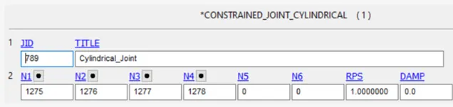
The nodes N1 and N3 must be in rigid body A. The nodes N2 and N4 must be in rigid body B.
4.The velocity is defined using the keyword intial velocity.
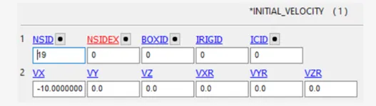
The nodeset id and control cards remains the same for the two cases.
Spherical joint
1.Repeat the step 1 and 2 as given in the spherical joint for rigid bodies .
2.The material and section cards remains the same as the previous joint between deformable bodies.
3.Create the CNRB nodes shown below. Only CNRB nodes has to be created. Constrained extra nodes should not be used.
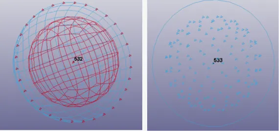
4.The spherical joint is defined using the keyword constrained joint spherical.
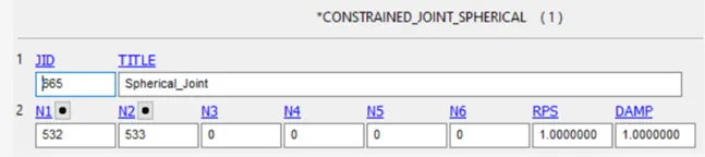
The nodes N1 and N2 must be in rigid body A and B respectively.
5.The velocity is defined using the keyword initial velocity.
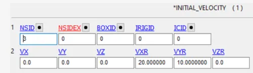
The nodeset id corresponds to the rotating sphere part.
The run time and control cards remains the same for the two cases.
Translational joint.
Repeat the steps 1-3 as given invthe joint definition of translational joint between rigidbodies. The material and section cards remains the same as the previous cases of joint between deformable bodies.
Create the CNRB nodes as shown below. Only CNRB has to be created constrained extra nodes should not be used.
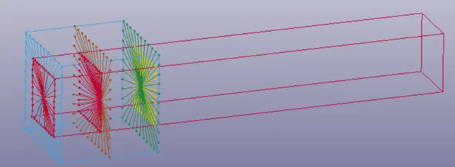
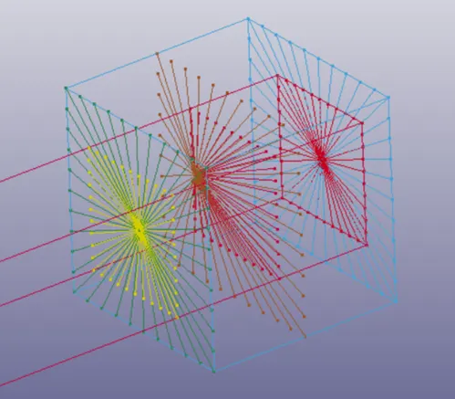
The joint definition remains the same but the way of implementation differs
The translational joint is defined using the keywordconstrained joint translational
4.
revolute joint deformable

cylindrical joint deformable
spherical joint deformable
Translational joint deformable
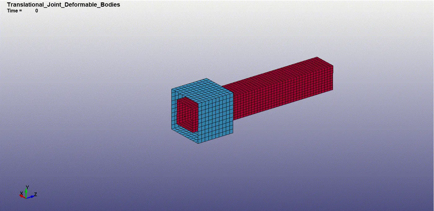
the simualtion run time for joints between deformable bodies is more than the rigidbodies.this is due to the calculation of stress and strain values in the case of deformable bodies.
the definition of joints for the two cases remains the same .the way of implementation differs.
if we use the elastic material card and the joints using constraints extra nodes we will get an error.
there are two methods adopted because of the silver limitations and capabilities.
conclusion
all the given joints are modelled for rigid and deformable bodies.all the objectives are satisfied .the following points were learned from this challange.
revolute joint : these are defined by two pair of nodews which are coincident to each other ,only a rotational degree of freedom is possible along the axis of nodes.
cylindrical joint: these are defined by two pairs of nodes that are coincident along the center axis of two bodies.in this joint rotation and translation is possible along the defined axis.
spherical joint: this sis defined by a pair of nodes.only a rotational degree of freedom is possible for this type of joint.
translational joint: these are defined by three pair of nodes . the third pair of nodes is offset from the center axis nodes which restricts the rotational degree of freedom.only a translational degree of freedom is possible along the defined axis.
G link.
https://drive.google.com/file/d/1nrktzsT7wZSpwYGBwzNM7AYiHkqufLXx/view?usp=sharing