week-11 Joint creation and Demonstration
AIM :
To create revolute, cylindrical, and translational joints between two rigid bodies and two deformable bodies Using the Ls-Dyna Solver.
Case-1:Revolute Joint Between Rigid Bodies :
1. Create Two-4 Noded Shell Using Mesh > Shape Mesher > 4 noded Shell. and enter the Coordinates in P1, P2, P3, P4.
2. Assign 1 shell Component as part and another one as part-2
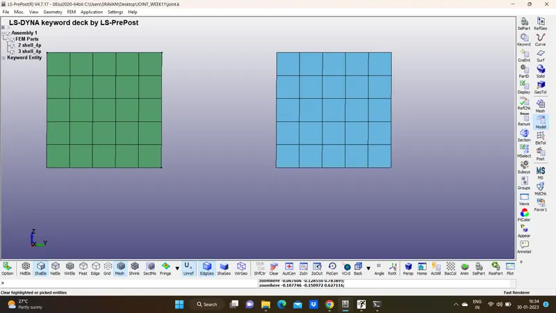
Create 4 nodes In between the Shell and note their Id.
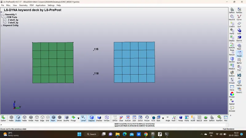
Create a Node set consisting of Nodes 113 and 114 and another Nodeset consisting of 115 and 116
Create a Section for the Shell components with ELFORM=2 and with thickness 1.5
The Node set ID Which contains Nodes 181,182 is considered as Fixed Nodes assigned to the part-1 which is also Fixed
The Node Set ID Which Contains Nodes 113, 115 Which in Coincided With 114 and 116 is Considered as Moving Nodes Is Assigned to part 2
Constrained_Joint_Revolute :
Constrained Joint Revolute Is defined And The Nodes which are Coinciding are Entered.
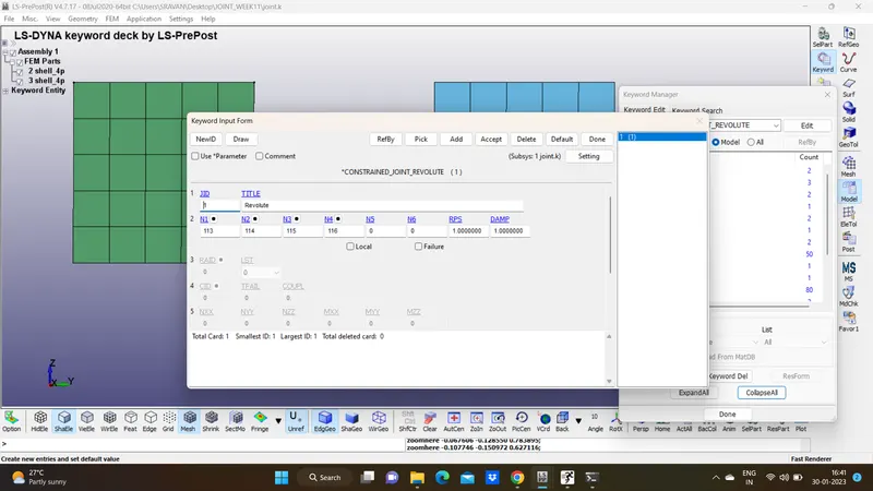
Displacement :
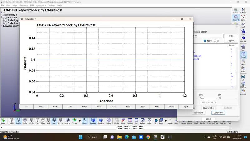
Displacement is Given to A node in any one of the Parts By defining displacement Curve, here displacement is given to a node belongs To part-2
As the Displacement Is Given to the Nodes from Part-2, part-1 Is constrained In all DoF's
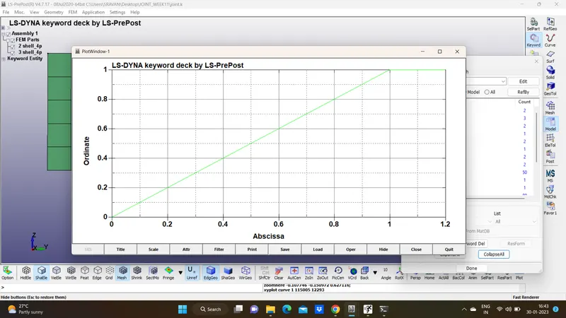
Control-cards :
1. Control cards Such as Control Termination, Control implicit Auto, Control Implicit General, And Control Time step Is defined
2. As Displacement is given Implicit Solver Is chosen for Better results
Control Termination Card Is defined With the Termination Time 1ms
Database Binary D3Plot is defined To print the Results at 0.1ms in each interval
Contol Timestep Card is defined For Stable Time Step
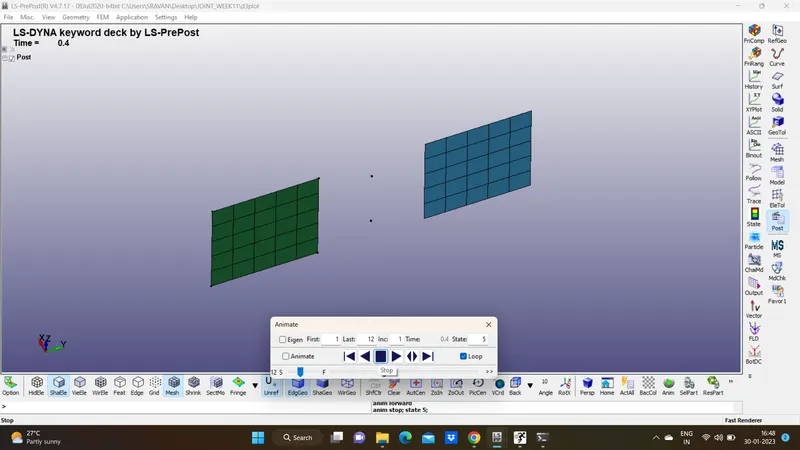
Result:
CASE-2 : Revolute Joints between Two Deformable Bodies
1. For Deformable Bodies The Constrained_Extra_Nodes is Replaced with Constrained_Nodal_Rigid_Body
2.Mat_Elastic is defined instead of Mat_Rigid
3.Here Mat_elastic card is defined with The properties of Steel