Week 11 - Final project
AIM:
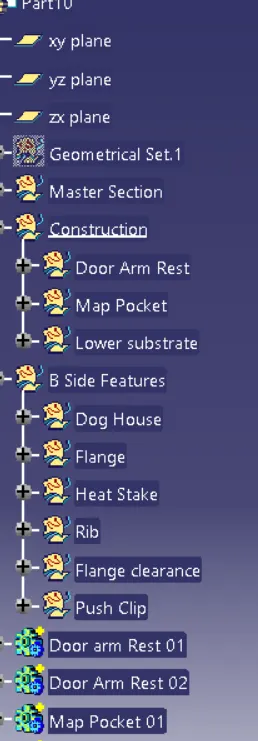
To create Class B and Class C surface with the given Class A surface and also create the B side features using the given master section by using Catia V5.
TOOLS REQUIRED:
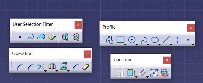
SKETCH TOOLS:
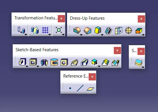
PART WORKBENCH TOOLS:
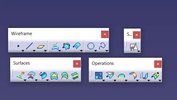
SURFACE WORKBENCH TOOLS:
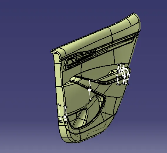
GIVEN INPUT :
FEATURES TO BE CREATED:
- Class B Surface
- Class C Surface
- Dog house
- Flange
- Heat Stake with Ribs
CLASS A SURFACE:
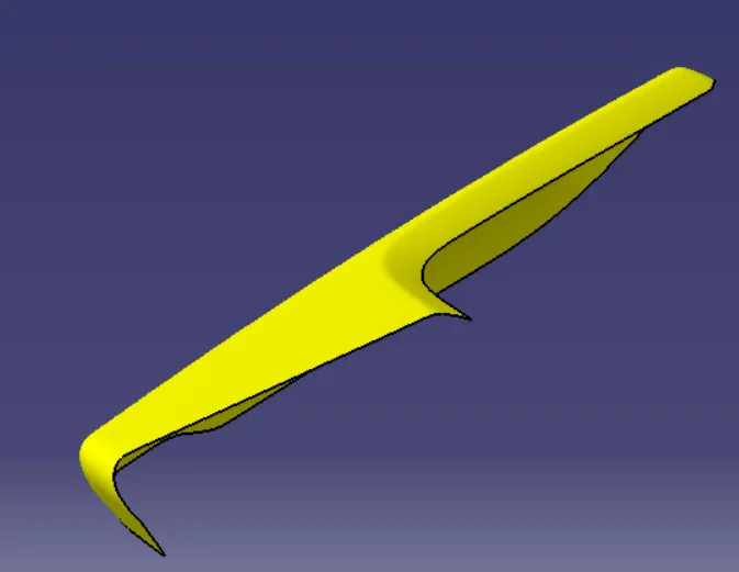
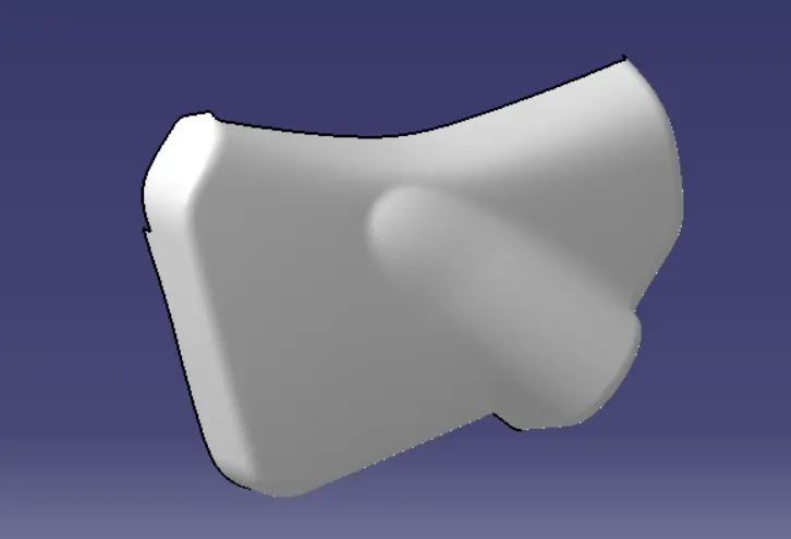
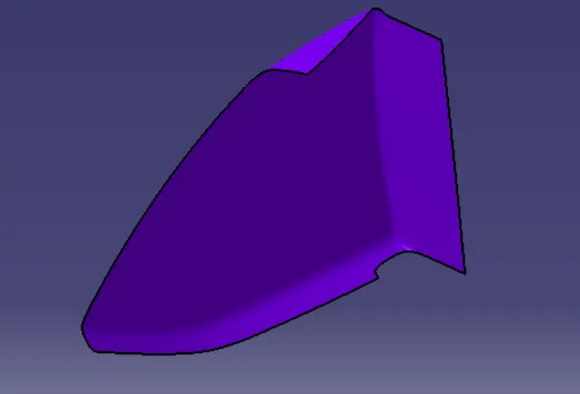
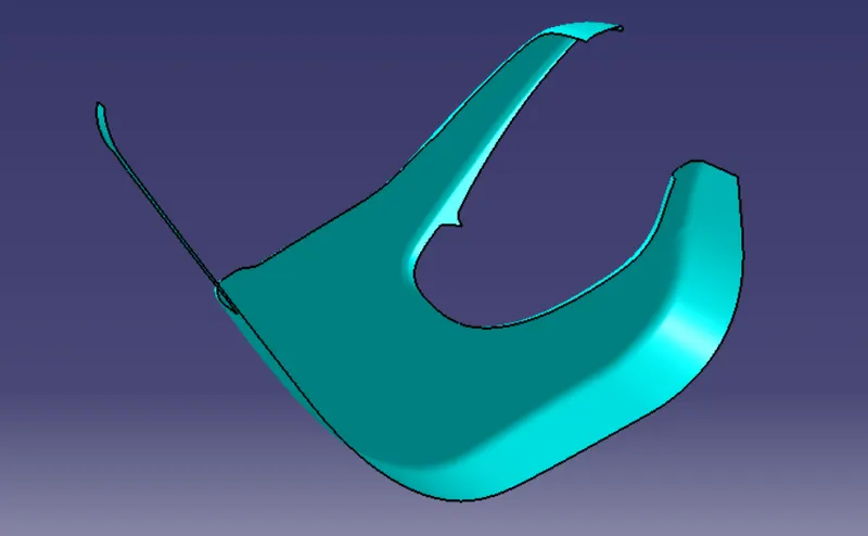
The given input has lower substrate, map pocket, door arm rest and the upper substrate.
we have to work on lower substrate, map pocket and the door arm rest.
we have to join the surfaces seperately with respect to the areas.
The door arm and the map pocket are seperated into two surfaces to work easily.
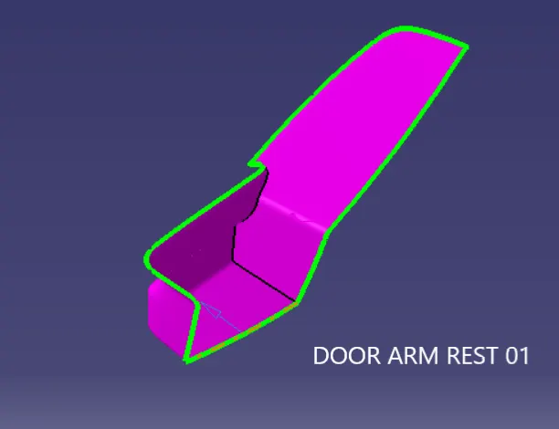
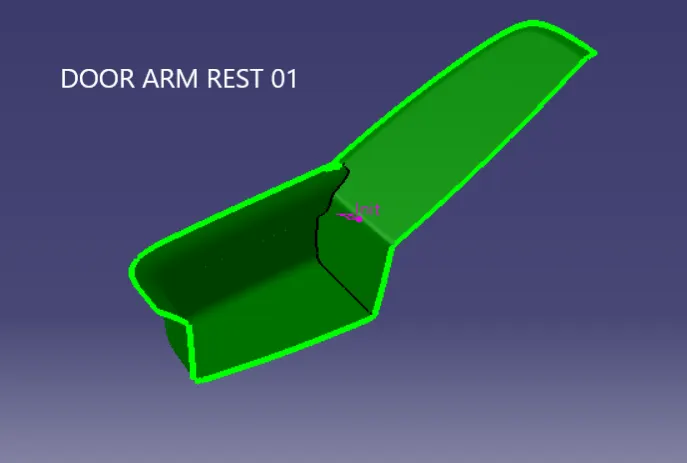
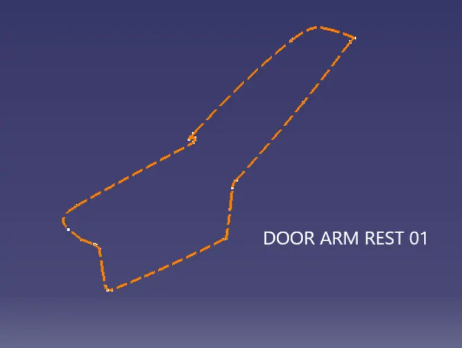
CLASS A OF DOOR ARM REST 01
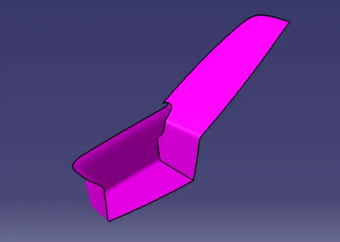
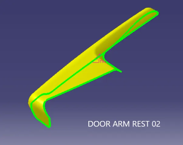
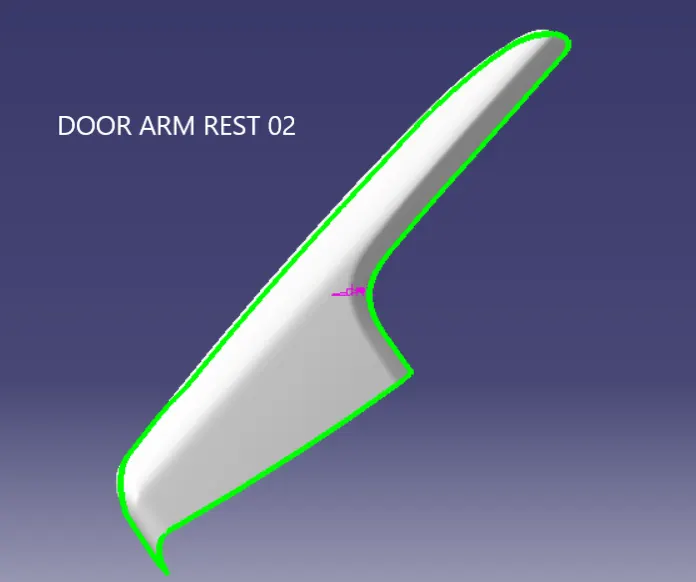
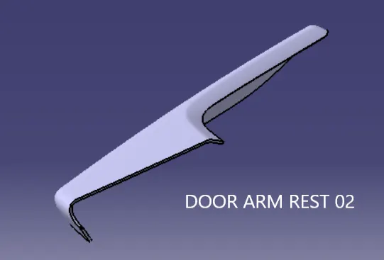
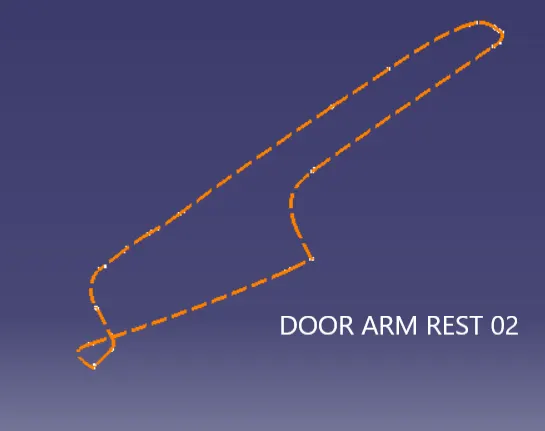
CLASS A OF DOOR ARM REST 02
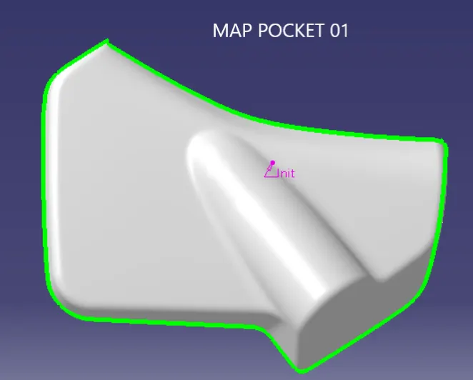
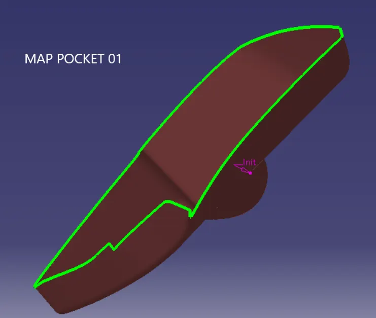
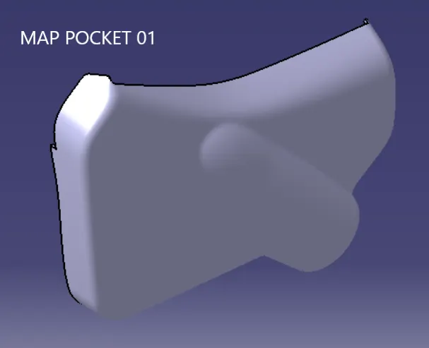
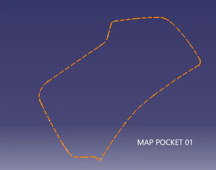
CLASS A OF MAP POCKET 01
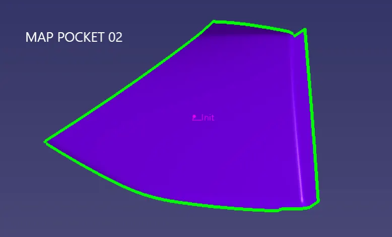
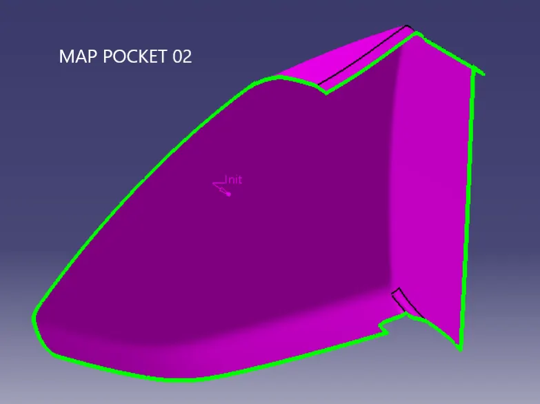
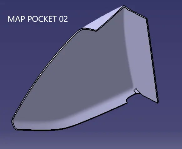
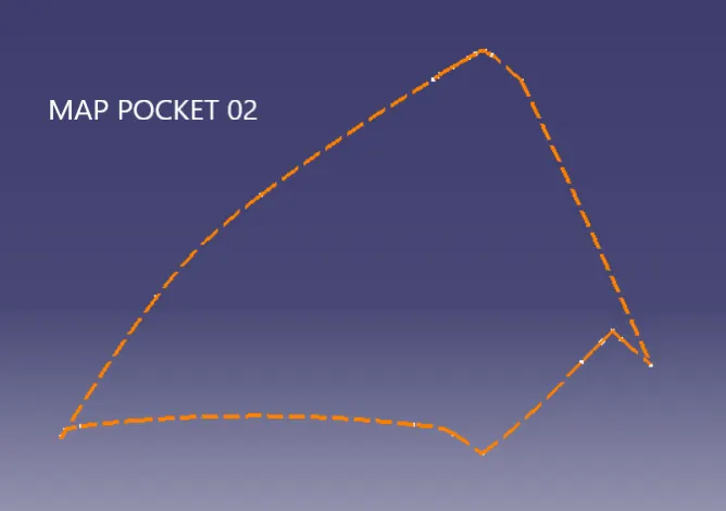
CLASS A OF MAP POCKET 02
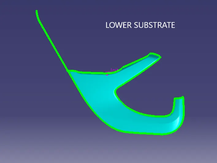
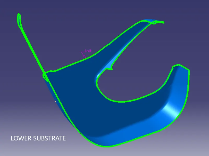
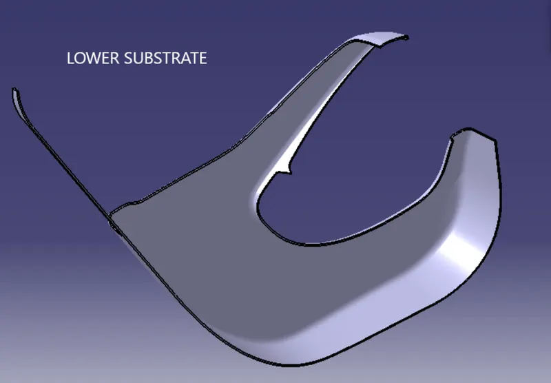
CLASS A OF LOWER SUBSTRATE
BOUNDRY OF CLASS A SURFACE:
The boundry of class A surfaces are checked for any gap or discontinuity in the surface.
TOOLING AXIS AND DRAFT ANALYSIS:
Tooling axis is created with respect to the mould direction and also for the area which need to be drafted.
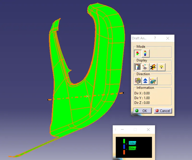
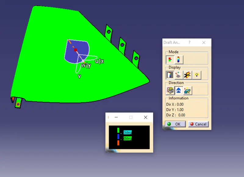
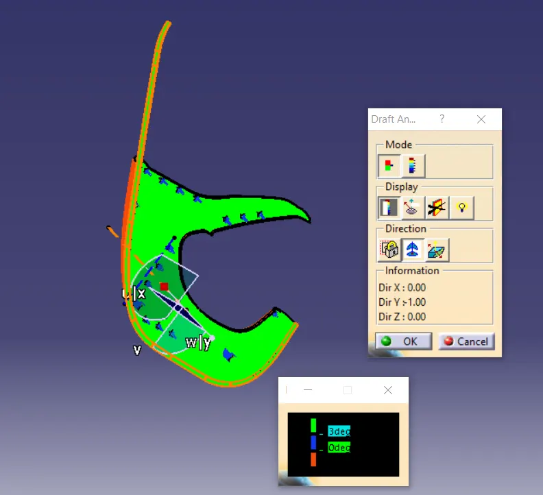
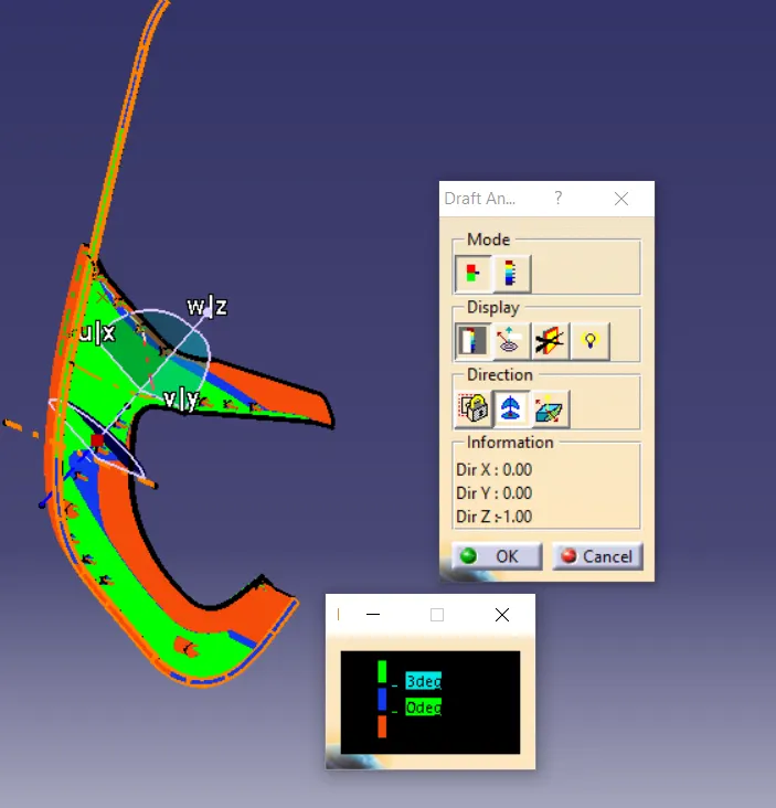
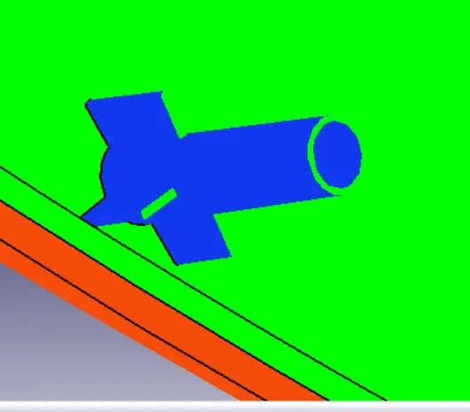
Draft analysis is done on the Class A surface to define the clearances using the colour code and measure the draft angle.
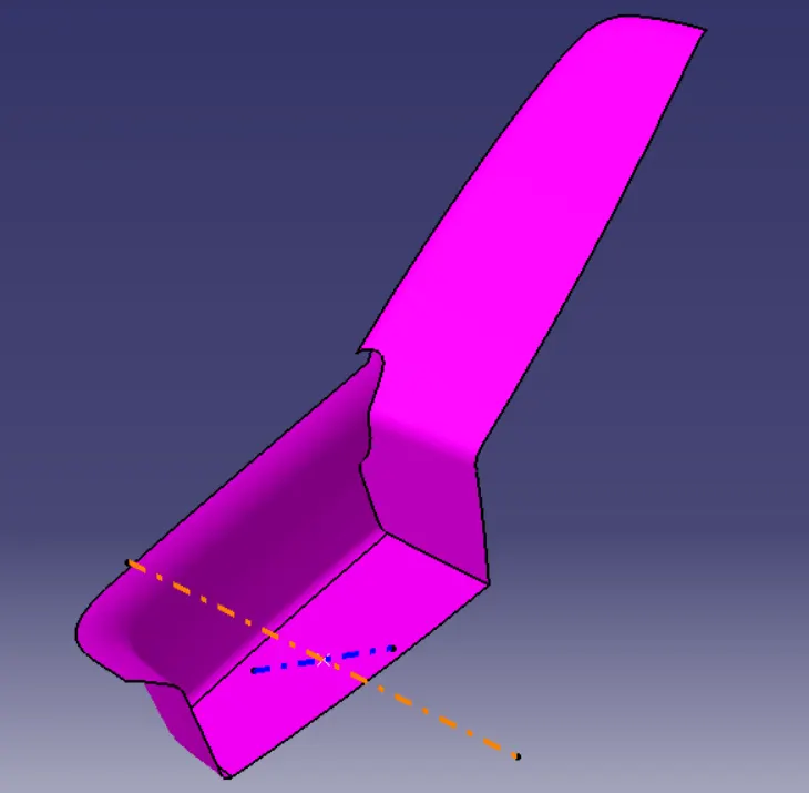
DOOR ARM REST 01:
Create a extract at the bottom side of the surface.
Create a point at the centre of the extract .
Draw a line using the point and in the Z direction.
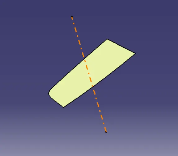
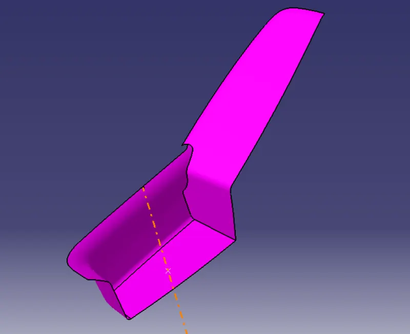
Draft analysis on the Class A surface by dragging the compass in the tooling axis and click on the part that gives the colour code.
Rotate the compass until the whole door arm rest 01 changes into green colour.
Lock the compass direction and give the line direction in the compass direction.
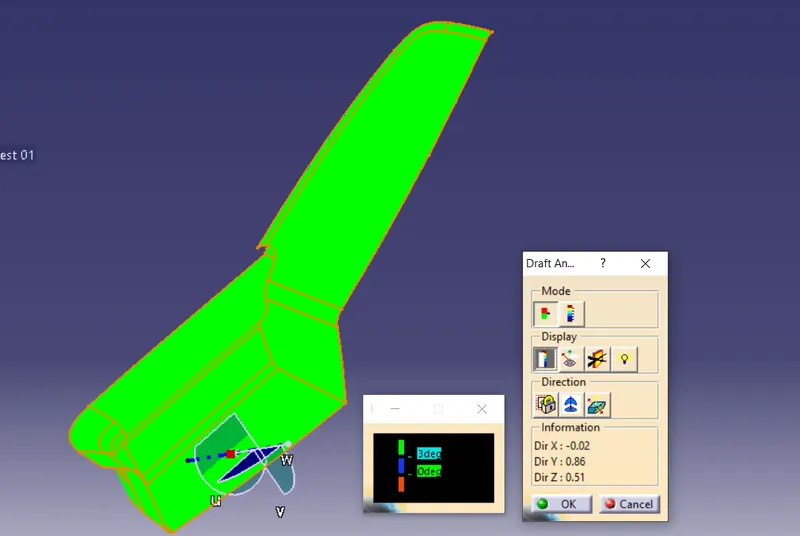
The created line is the Slider axis.
A main axis is drawn in the direction of Y axis for the further clearance of B side features that will be explained in the draft analysis of part body.
DOOR ARM REST 02:
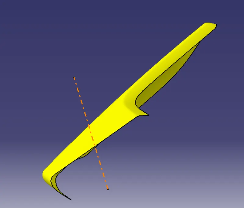
Create a line in the direction of Z using the point in the Class A of Door Arm Rest 02.
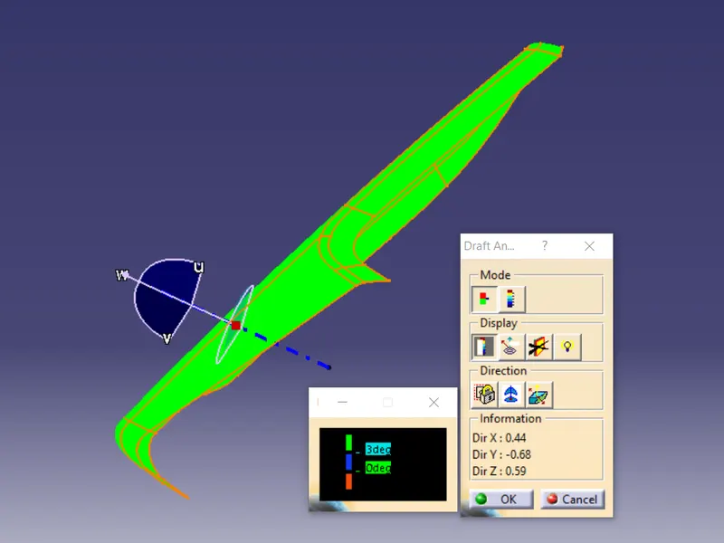
Simalarly use this line for draft analysis by dragging the compass in line with it.
Adjust the compass until the class A becomes green.
Lock the Compass direction and make the line direction in compass direction.
It is used as the slider axis.
MAP POCKET 01:
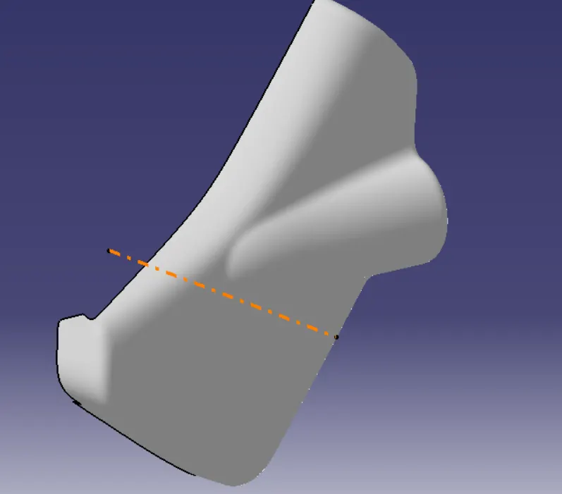
Create a line using the vertex of the class A surface in the direction of Z.
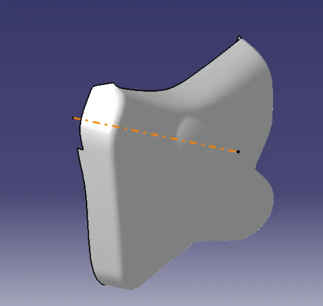
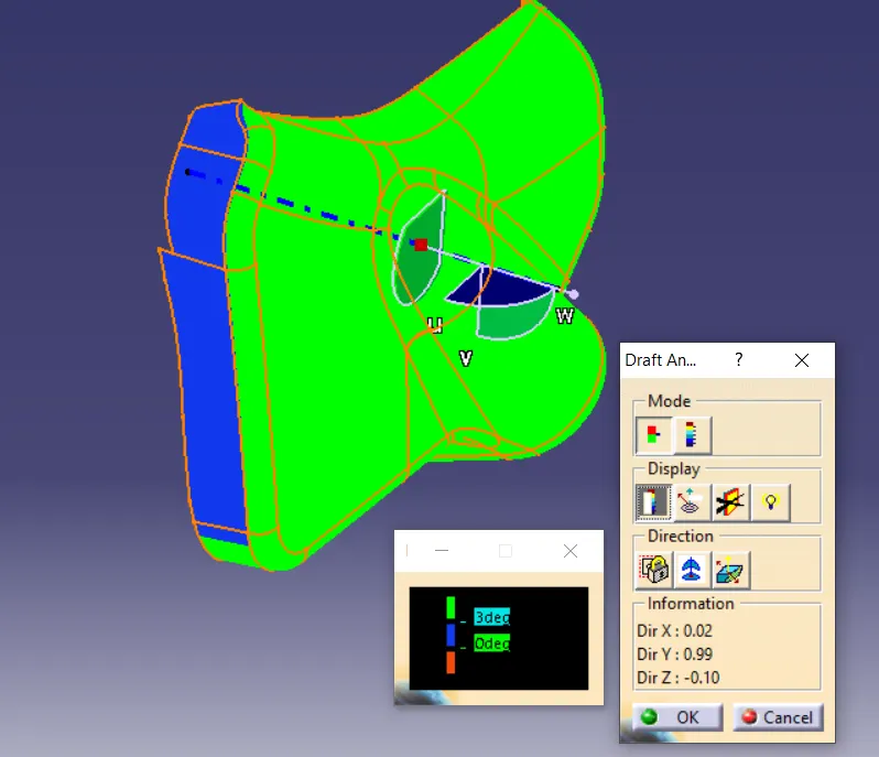
we have to do a draft analysis on the class A surface by dragging the compass in line with the created line .
Rotate the compass until the class A becomes Green and lock the direction of compass.
Change the line direction into compass direction make it as a slider axis.
MAP POCKET 02:
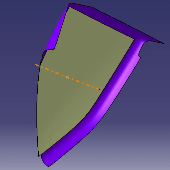
Extract the bottom face of the map pocket 02.
Create a point at the centre of the extract and draw a line using the point in the Z direction.
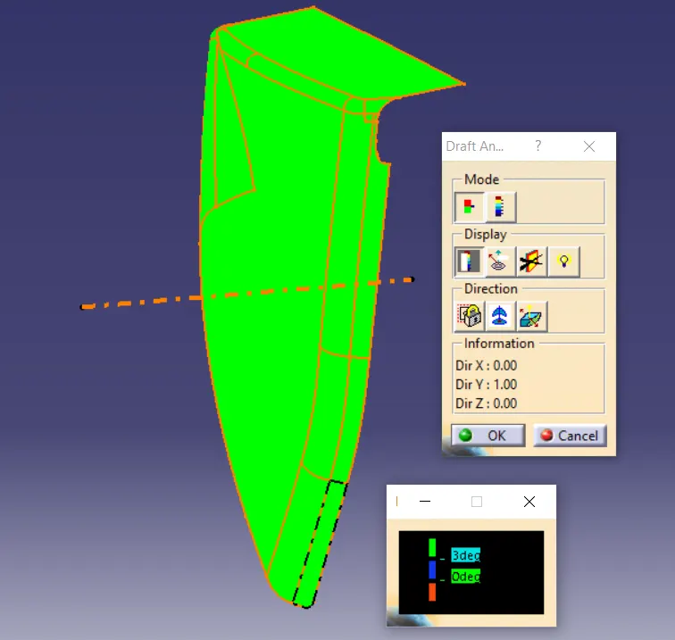
Do the draft analysis by dragging the compass inline with the created tooling axis .
In this map pocket we don't have to rotate the compass because it shows green in Z direction itself.
LOWER SUBSTRATE:
Create a line in the direction of Z using a point.
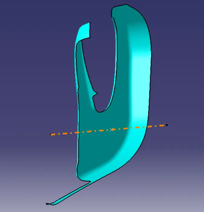
On donig the draft analysis by dragging the compass inline with the created one .
There is no need to rotate the compass because it shows the green colour in the Z direction itself.
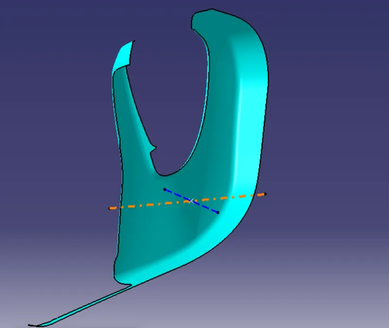
But we have to create the tooling axis in the Y direction also for the clearance of B side features.
Here the Tooling in Z direction is the main tooling Axis and the one in Y direction is the slider axis.
CLASS B SURFACE
Part body is a closed feature, but Class A is a surface .
We have to create the part body from the surface, for that we have to create a Class B Surface.
The class B Surface is nothing but the other side of the part body , but it is also a surface that is exactly in the shape of the Class A surface.
The Class B surface is created by just offsetting the Class A surface.
The offsetting distance should be the thickness of the part.
DOOR ARM REST 01:
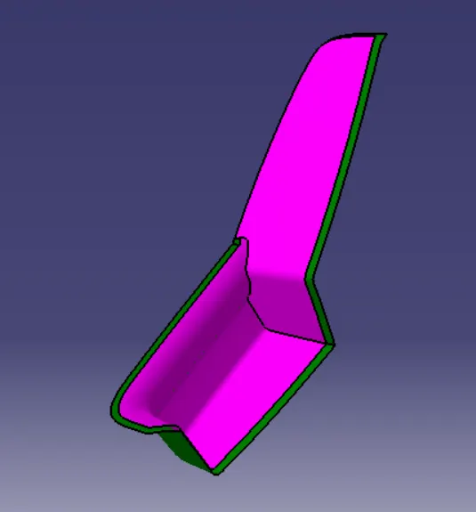
Here we have to offset the Class a surface to the bottom side at a distance of 2.5mm.
Refer the given Master section for the thickness of the product.
During offset some surfaces may not offset properly , so try to do the improper surface using Multisection surface and join it with the offseted one.
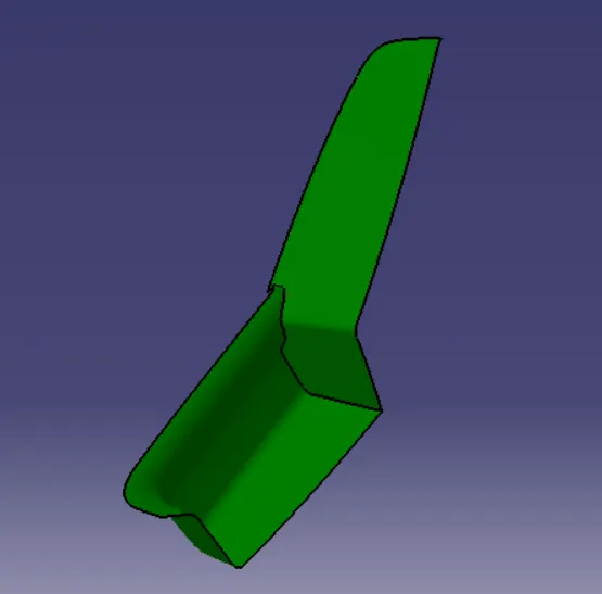
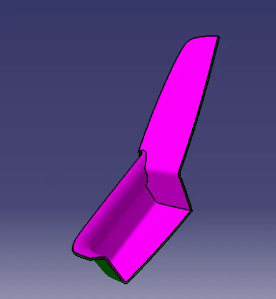
Extrapolate the Class B surface for a certain distance so that it will interact with the Class C surface while trimming.
DOOR ARM REST 02:
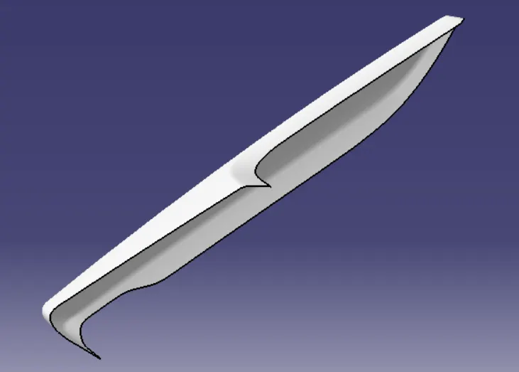
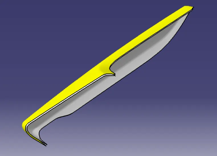
As per the master section the given thickness is about 2.5mm.
so that the class A surface is offseted to a distance of 2.5mm to the bottom side.
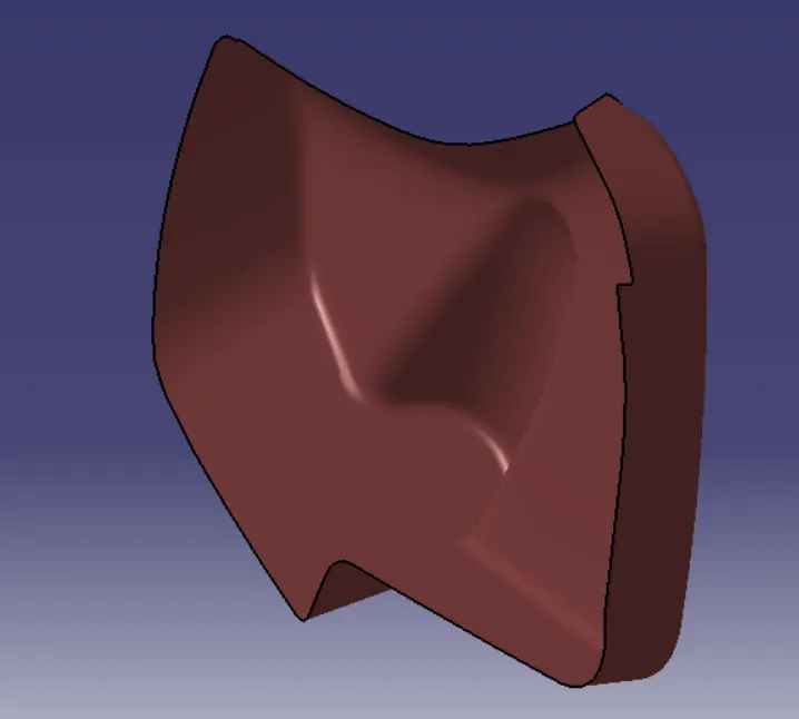
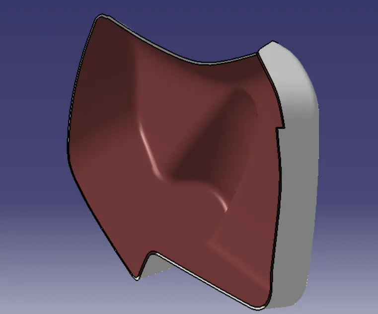
MAP POCKET 01:
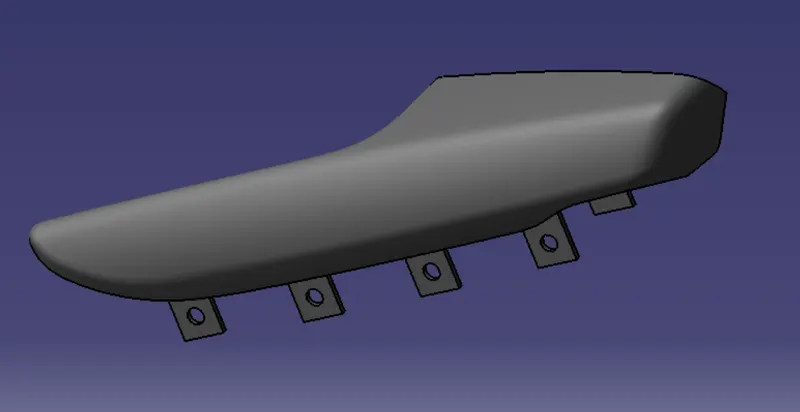
Class A Surface is offseted to a distance of 2.5 mm.
The Class A is offseted as per the mastersection.
MAP POCKET 02:
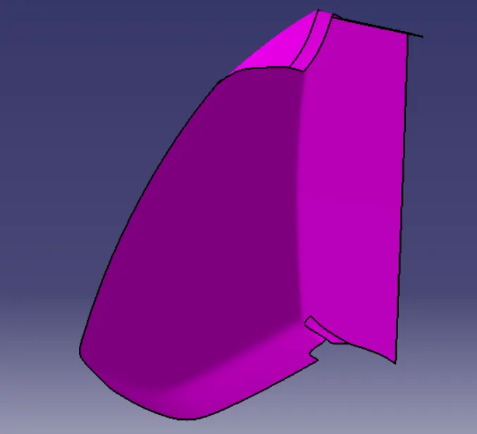
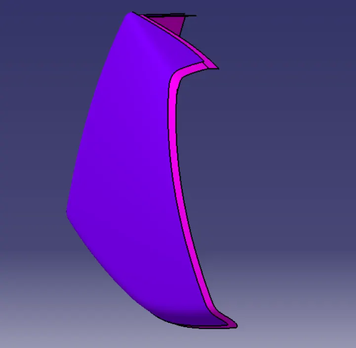
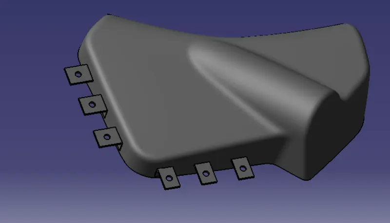
Class B is created by offseting the Class A surface at 2.5 mm.
While offseing some of the areas are not offseted properly so we have to do multisection surface on that area and join with the Class B Surface.
Extrapolate the Class B surface for certain distance so that it interact with the class C surface .
LOWER SUBSTRATE:
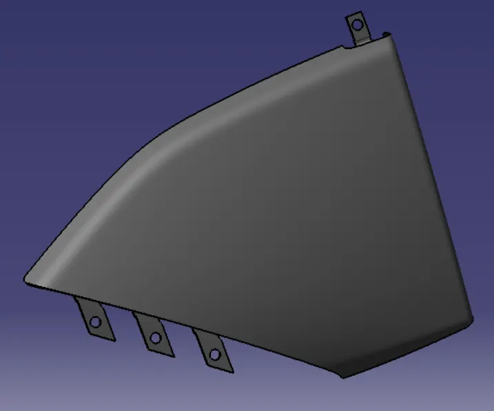
As per the given master section the Class A of lower substrate is offseted to the bottom side to a distance of 2.5mm.
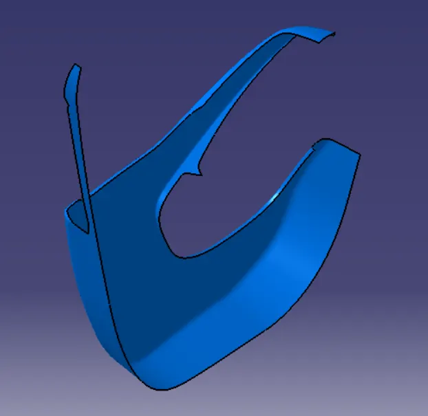
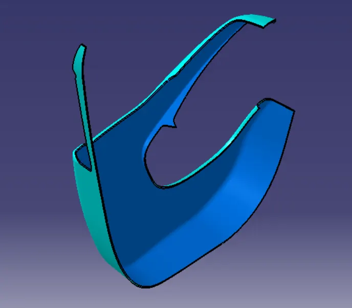
BOUNDRY OF CLASS B SURFACE:
CLASS C SURFACE
Class c surface is nothing but the surface that used to join the Class A and B surfaces.
The class C surface can be formed in either of the three ways , the ways are
- Sweep
- Blend
- Multi section surface.
DOOR ARM REST 01:
The boundry for Class a surface is created .
Sweep the boundry in draft direction using the main tooling axis at 0 degree.
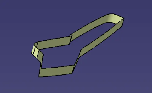
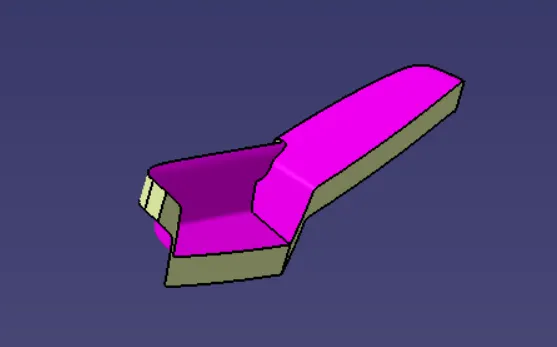
Join the Class A surface with the Sweep .
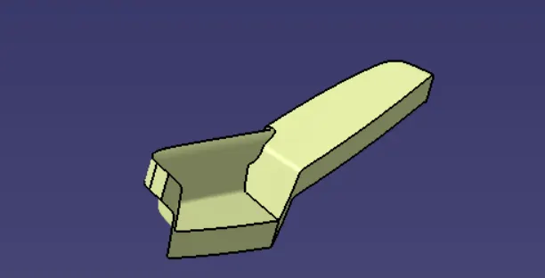
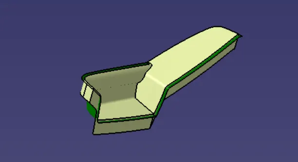
Trim the join with the extrapolated Class B surface.
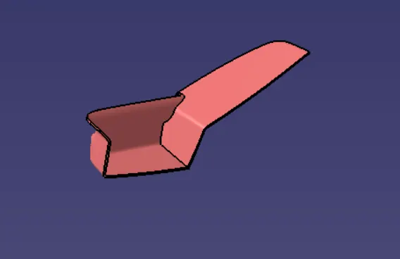
when creating a boundry after this it should be invalid.
DOOR ARM REST 02:
Create a boundry for both class A and Class B surfaces.
Create a multisection surface using those boundries.
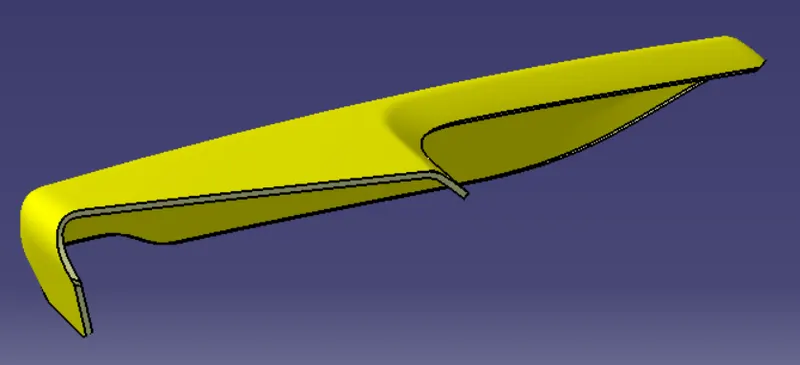
Join the multisection with the Class A surface.
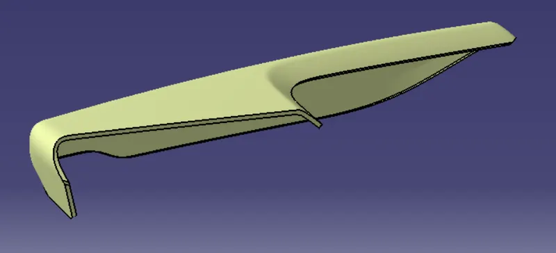
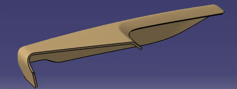
Finally Class B is joined with it.
MAP POCKET 01:
Create the boundry of Class A surface of map pocket 01.
Sweep the boundry with reference to the class A surface at 90 degree.
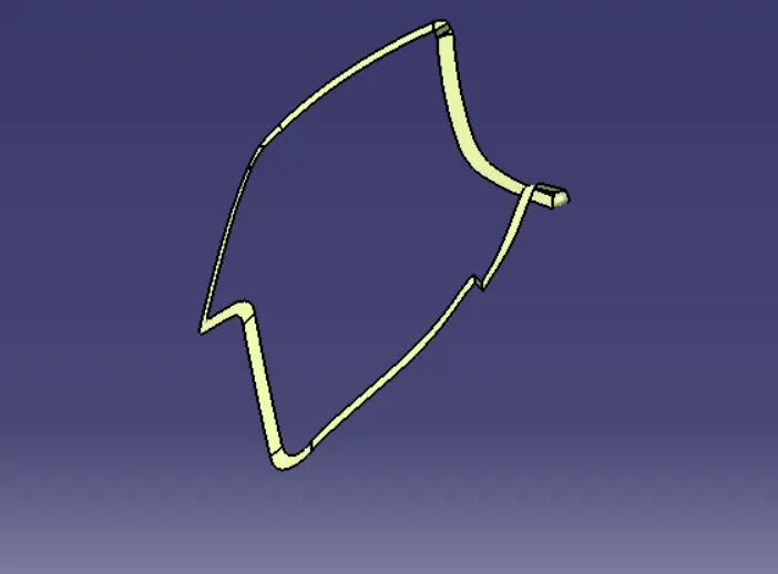
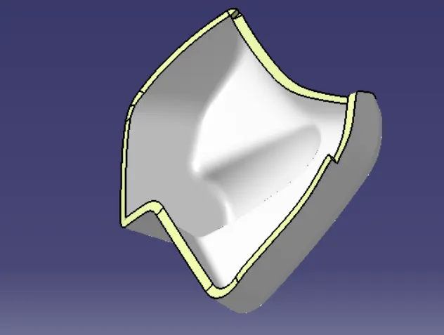
Join the sweep with the Class A surface.
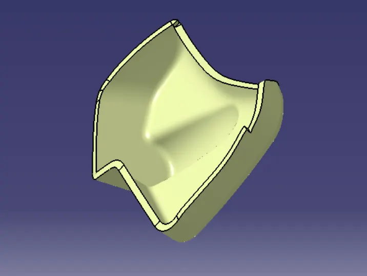
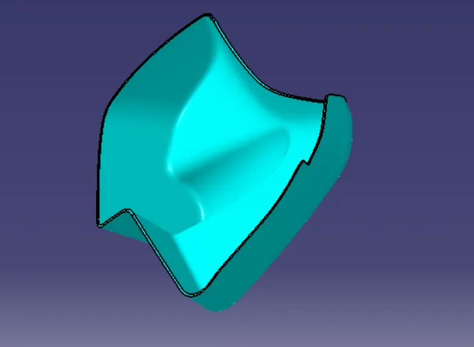
Finally trim it with the Class B surface.
MAP POCKET 02:
Create a boundry for the Class A surface .
Sweep the boundry with reference to the class A surface at 90 degree.
Sweep the boundry on both sides so that it interacts with the Class A surface.
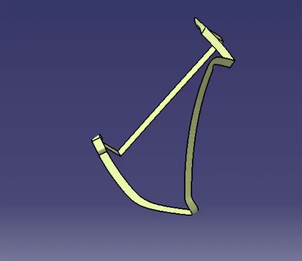
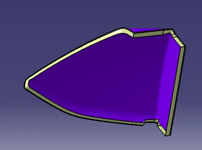
Trim the Class A surface and the Sweep.
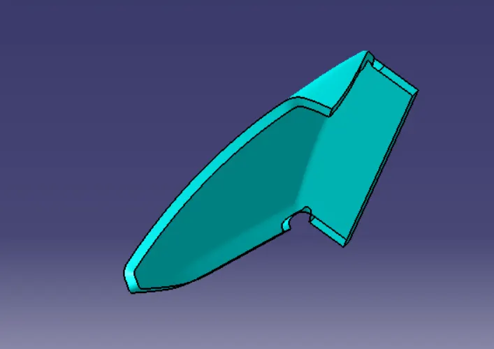
Trim the join with the Class B surface.
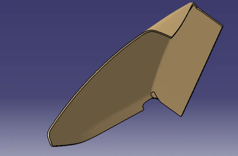
LOWER SUBSTRATE:
Here We have to use Blend to form a closed surface.
Use the extract or multi extract command to extract the boundries of Class A and Class B surface partially.
Extract the boundry part by part and blend it with the support as Class A and Class B respectively.
Trim the blends together .
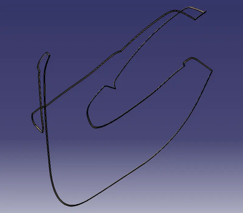
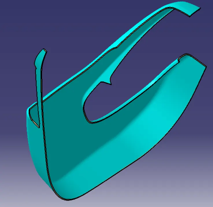
Join it with the Class A surface .
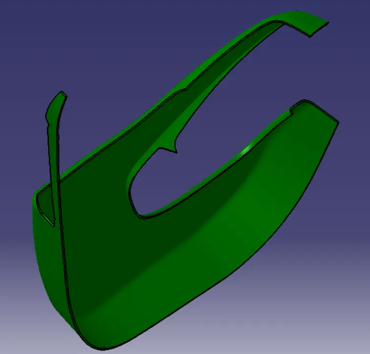
Finally join it with the Class B surface.
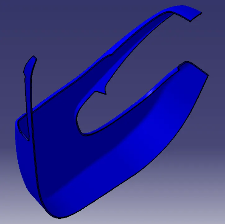
PART BODY:
Till here we have worked on surface, now we have to work on part work bench.
Now all the surfaces are closed , to ensure that try to create a boundry .
If the boundry is invalid then we can create the part body.
Using the Close Surface command the Closed surface is converted into part body.
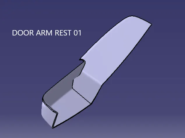
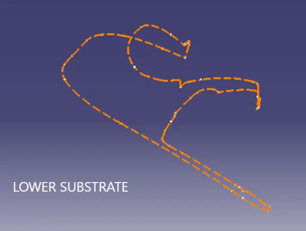
PARTING LINE:
The parting line is created with the intersection of two surfaces.
The first one is the joined surface of Class A and C surface.
The Class C is created by any one of the ways through sweep or multi section or by blend.
It may be trimmed or joined with the Class A surface , it has to be taken.
The second element is the class B surface that is created by offseting.
The parting line is the one that is used to create the parting surface that seperates the core and cavity.
B SIDE FEATURES:
FLANGE ON LOWER SUBSTRATE:
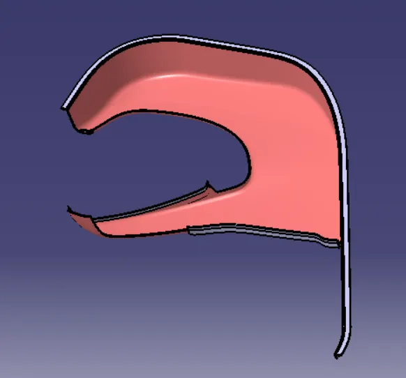
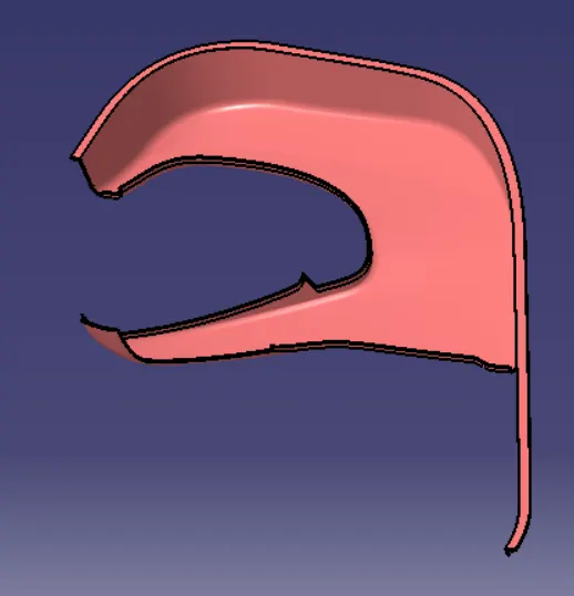
Here the given master section is divided into seperate ones with respect to the areas.
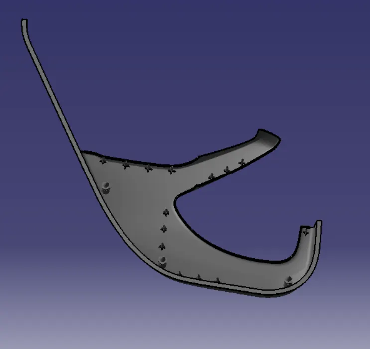
As per the master section 03 the edge of lower substrate is extracted and the extruded and made it into a thick surface.
The thick section is joined with the part body.
With reference to the master section 01 and 02 the boundry of lower substrate is extracted with no propagation and extruded.
Thicken the extrude to 2.5 mm.
The side flange is created with the use of sweep in draft direction and then thicken the sweep.
Join these with the lower substrate using the union trim .
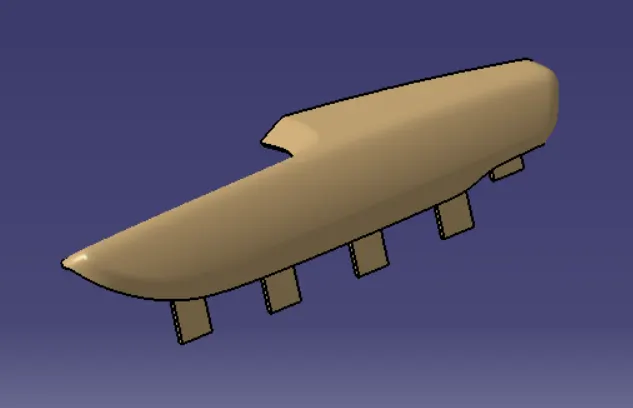
FLANGE ON DOOR ARM REST :
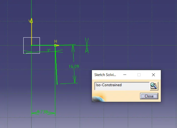
Master section 01 and 02 is related with the door arm rest.
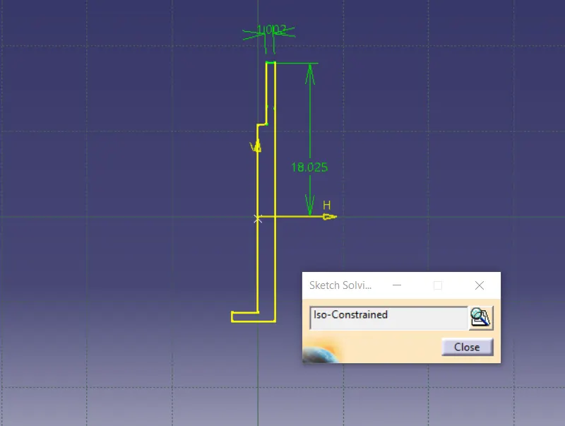
Create a positioned sketch .
The flange in the master section is projected and constrained.
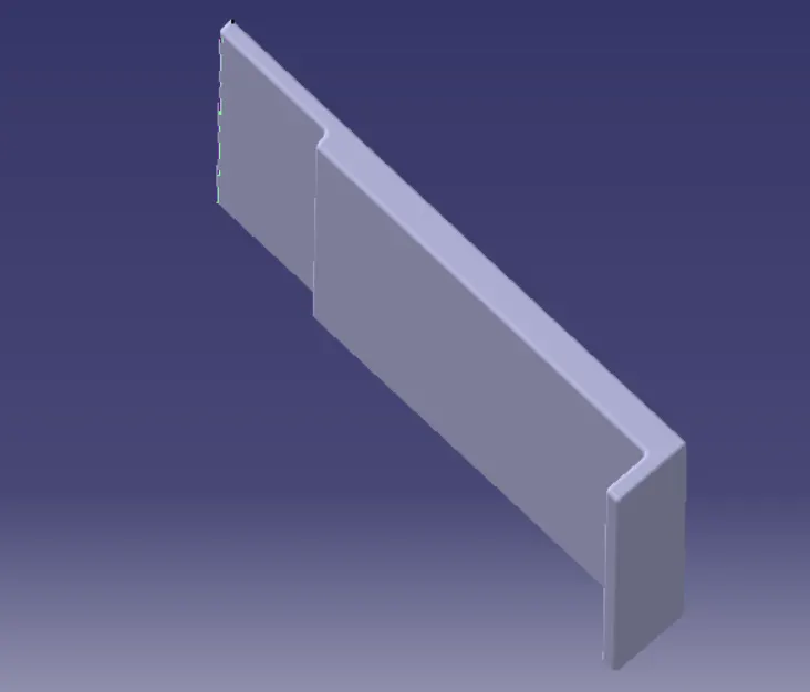
Pad the sketch with the thickness of 2.5 mm .
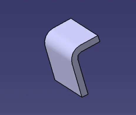
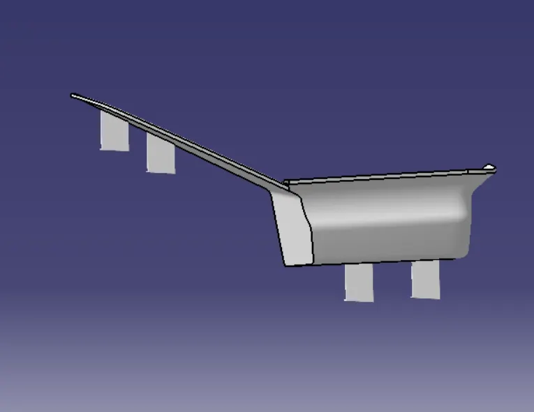
The same part body is copied and translated throughout the part.
The master section does not interact with door arm rest 01 so we have to create the flange on the other side of door arm rest 02 and translate ie to door atm rest 01.
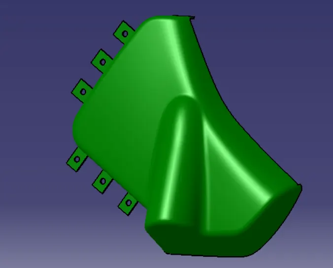
FLANGE ON MAP POCKET 01:
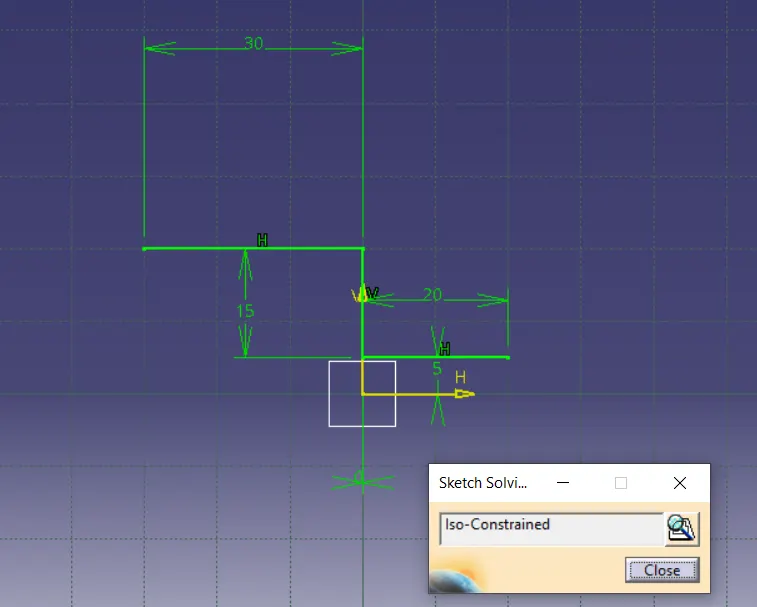
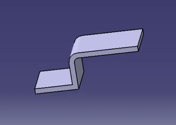
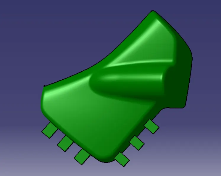
The given master section is not related with the map pocket 02.
so we have to create a sketch for flange .
Pad it with the thickness of 2.5 mm.
The same is copied and translated to different areas.
FLANGE ON MAP POCKET 02:
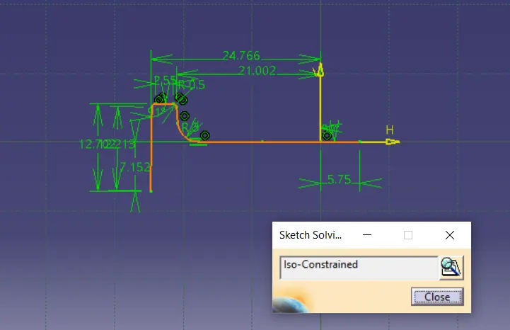
The master section 03 and 04 are related with the map pocket 02.
Create a positioned sketch and project the flange and constrain it.
Pad the sketch with thickness of 2.5mm.
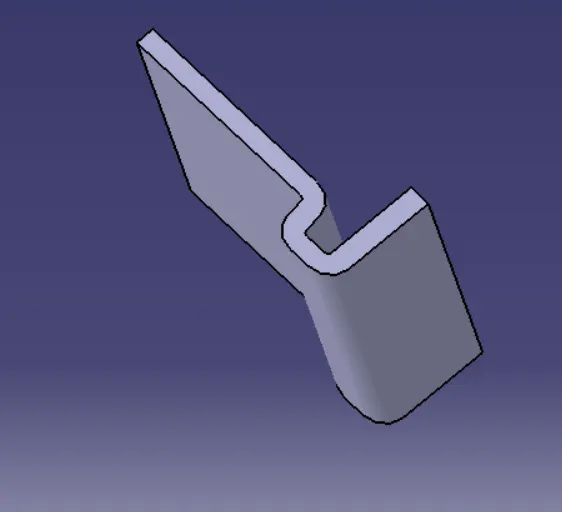
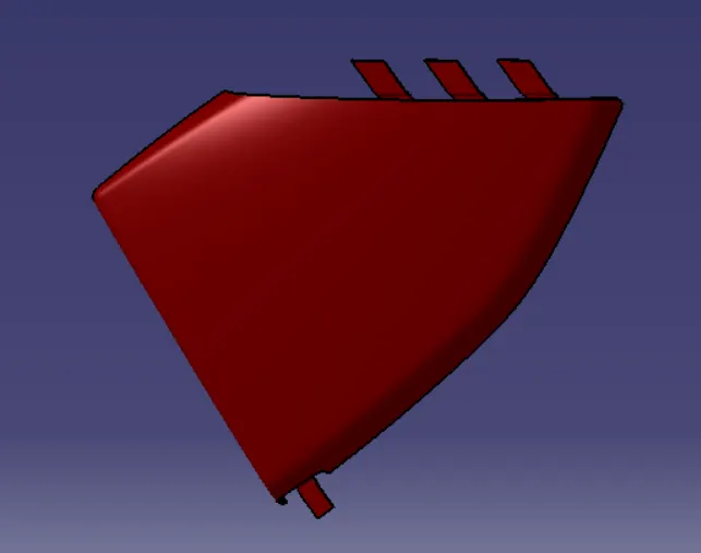
copy the body part and translate it.
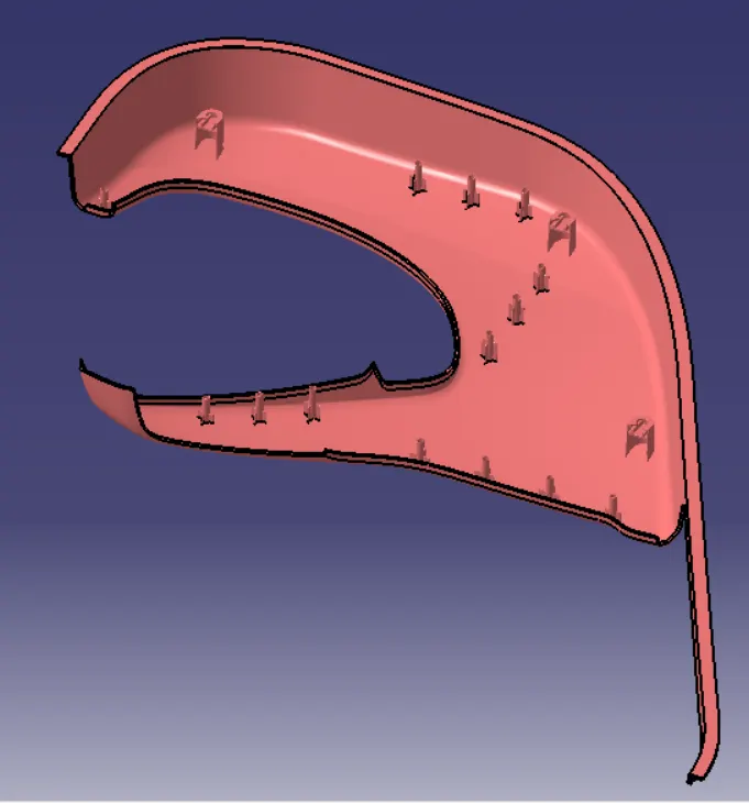
HEAT STAKE ON LOWER SUBSTRATE:
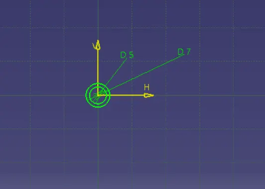
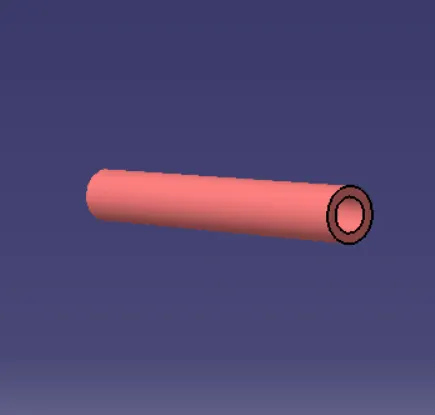
Create a sketch for the heat stake.
Pad it to the required distance.
Draft it on both sides .
Fillet the edges to about 0.25 mm.
RIBS NEAR HEAT STAKE:
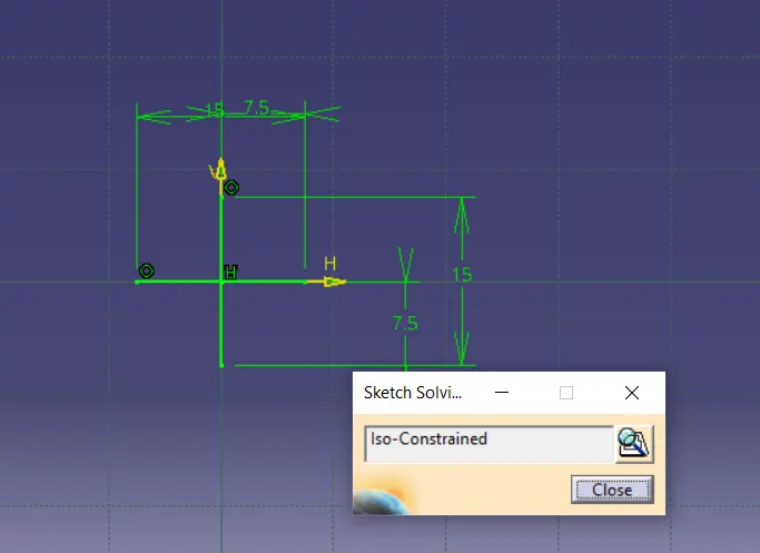
Create a positioned sketch on the same plane where the heat stake sketch is done.
Pad it to the required dimension and thick it to 1 mm.
Draft angle of 0.5 degree is given.
Fillet the edges to 0.25 mm.
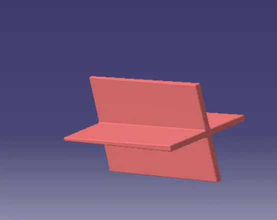
Union trim both the heat stake and ribs with the lower substrate.
Like this the heat stakes are created on the flange of other side of the door arm rest.
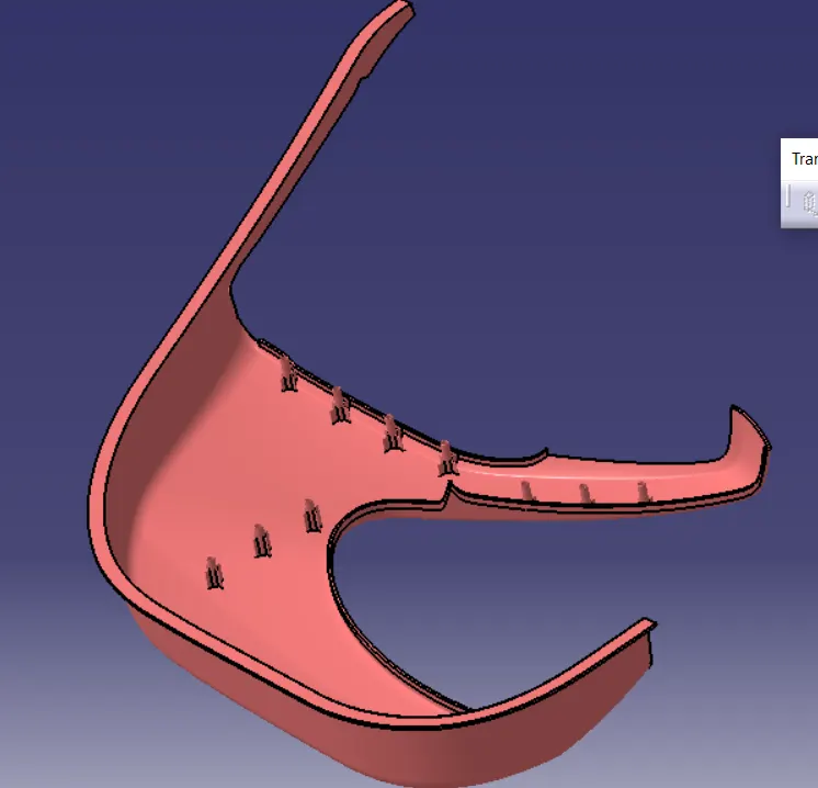
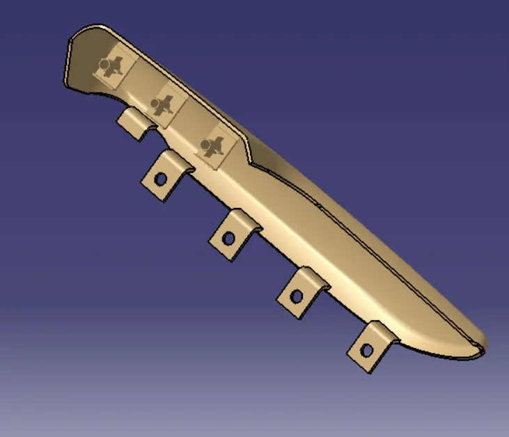
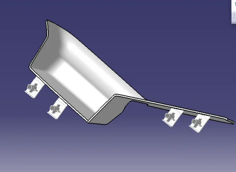
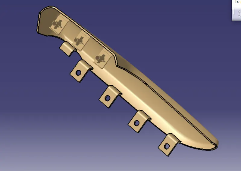
Clearances for these heat stakes are given on flanges by creating a sketch.
Pad it to the required dimension .
Copy it and translate to specific areas and remove them from the part body respectively.
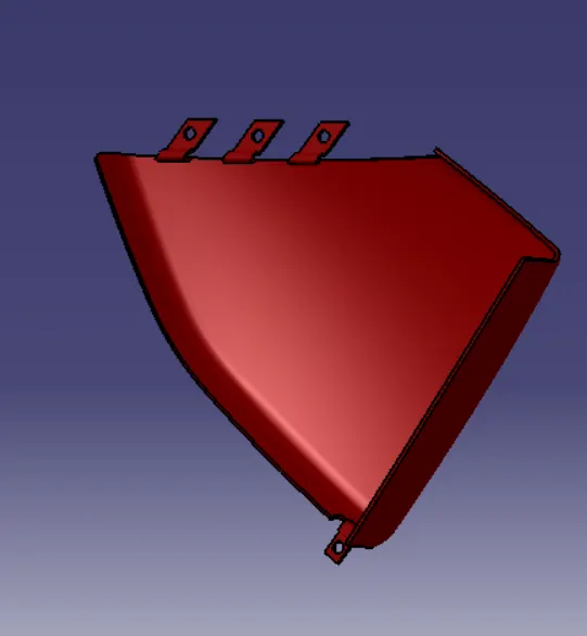
DOG HOUSE:
Create a sketch for the given dimension and pad it to the required height.
The part body is converted into shell with a thickness of 2 mm.
Again the top face is sketched and padded.
That pad is removed from the part body.
Create the ribs with the required thickess and union trim with the part body.
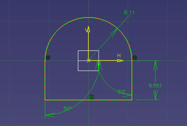
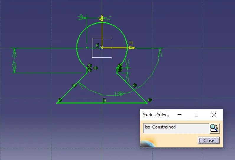
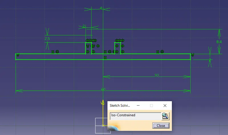
Extract the B surface to a height of 10 mm .
Create a extrude through the pad sketch and offset it to 1.2 mm.
Trim them together and create a thicken surface.
Draft the Thicken surface and remove it from the dog house that is named as C cut.
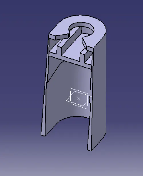
Union trim this with the lower substrate.
PUSH CLIP:
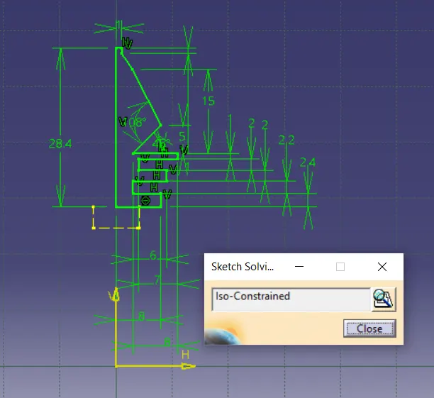
Create a sketch with the required dimension.
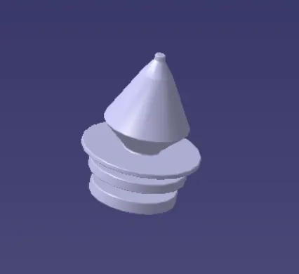
Insert a part body and create the part from the sketch using the shaft command.
Edges are filleted .
Part body is copied and translated to required dimensions.
Assemble this with the lower substrate.
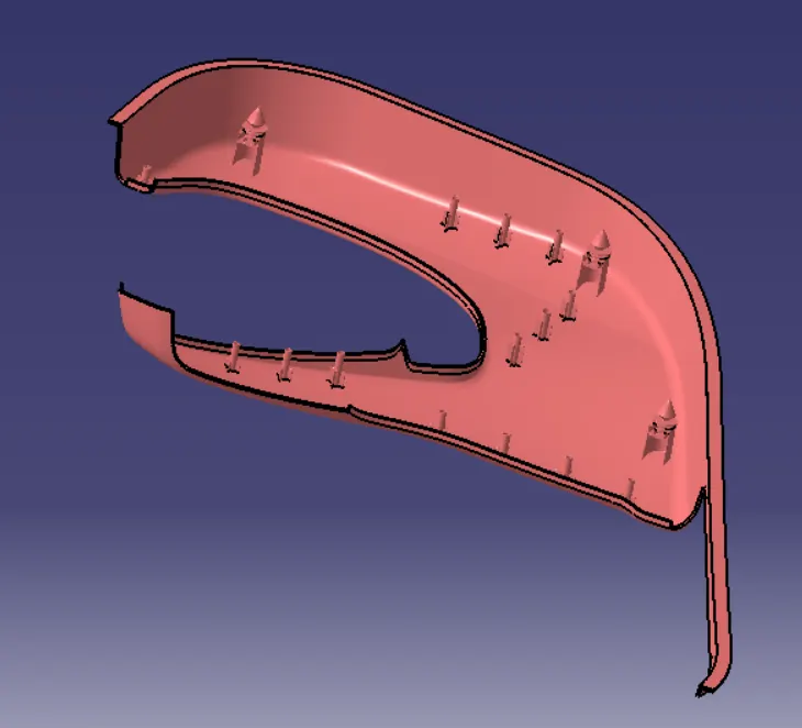
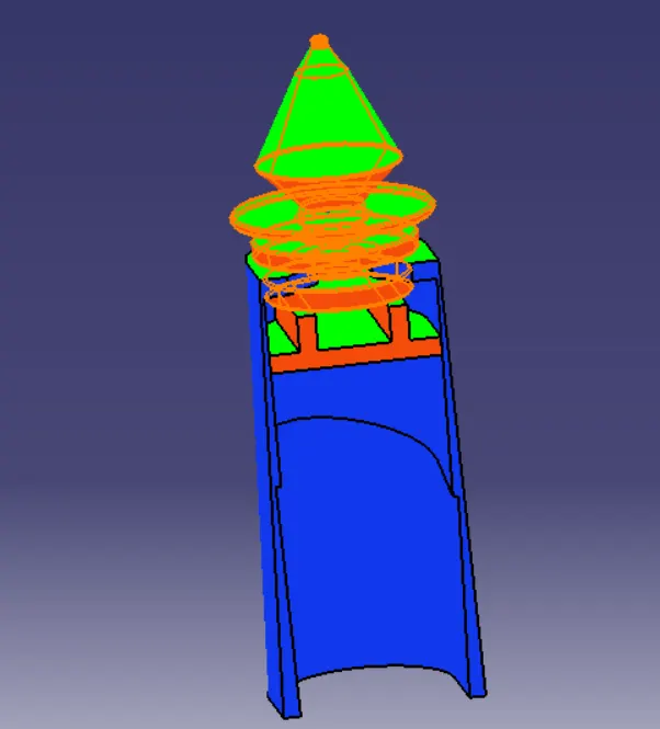
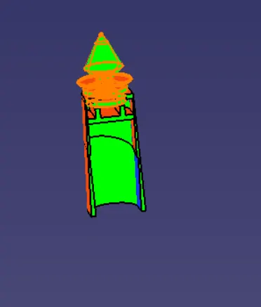
DRAFT ANALYSIS ON THE PART BODY:
DOOR ARM REST 01:
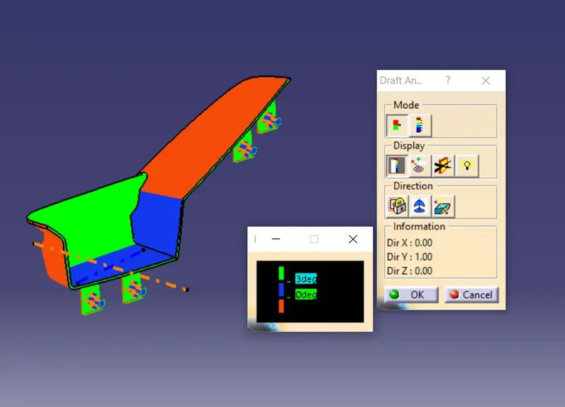
DOOR ARM REST 02:
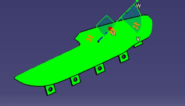
MAP POCKET 01:
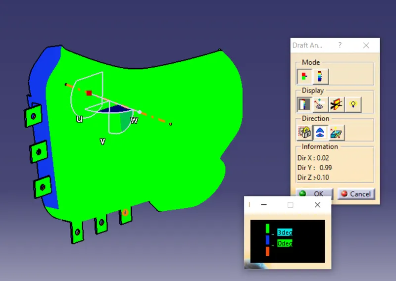
MAP POCKET 02:
LOWER SUBSTRATE:
ON APPLYING PLASTIC MATERIAL:
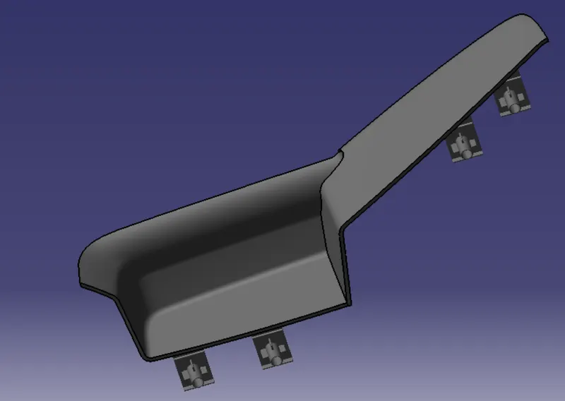
DOOR ARM REST 01:
DOOR ARM REST 02:
MAP POCKET 01:
MAP POCKET 02:
LOWER SUBSTRATE:
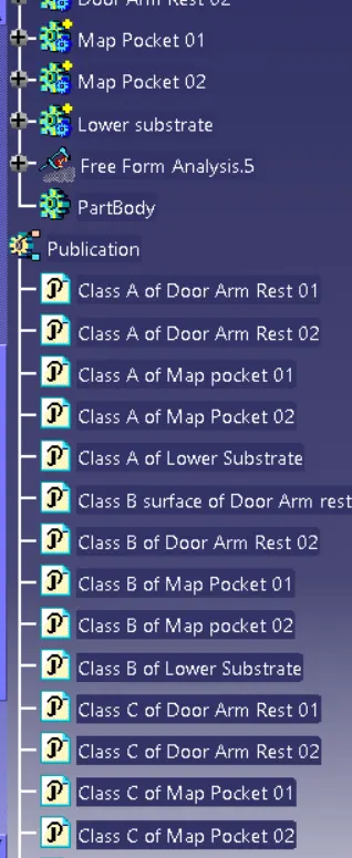
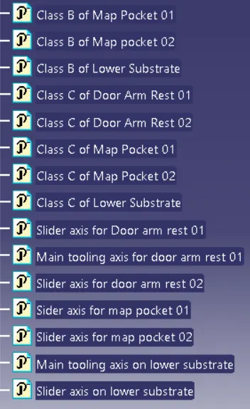
TREE STRUCTURE: