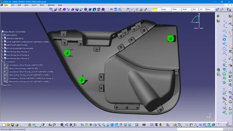
Week 11 - Final project
PROJECT : Developing the door trim with the Class A and Master sections given as input.
A product file is created and the Input file is opened and the parts are seperated out into different part files.
Tooling Axis Creation and Class A Draft Analysis
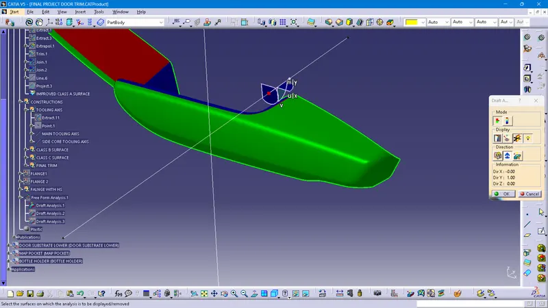
Arm Rest : Considering the whole surface, and conducting the visual inspection, a flat surface is extracted. Axis is created perpendicular to this surface and passing through the point in the centre of this surface. This axis is selected as the main toooling axis of the body. Draft analysis is conducted on this Class A surface with this tooling axis. Screen shot is given below.
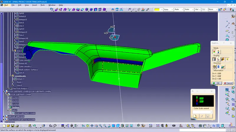
Some of the areas fails the draft analysis, as given below
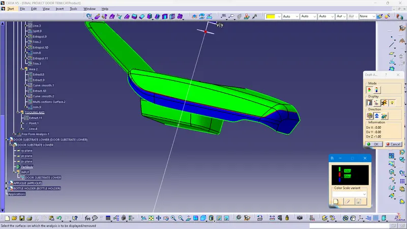
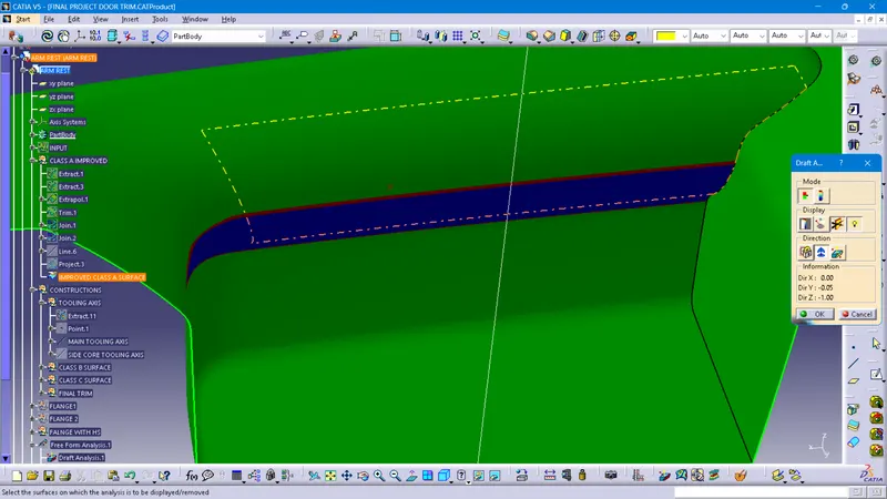
But these areas are impossible to tool with a single tooling axis. Various directions have been tried for tooling axis, but the selected tooling axis gives the maximum area satisfying the draft analyisis.
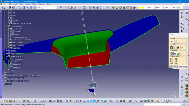
A side core tooling axis is required for the surface not satisfying the draft analysis with main tooling axis. Considering the other adjascent parts to be assembled, with this part y-axis is selected as the side core tooling axis.
Screen shots of draft analysis with side core tooling axis:
Door Substrate Lower:
As mentioned above, considering the adjascent parts to assembled, y-axis is selected as the main tooling direction of the body. An axis is created in this direction. This is because, if that is not considered, neighbouring components will not be assembled properly and cause problems. Draft analysis is conducted on the Class A surface with this tooling axis. Screenshot is given below.
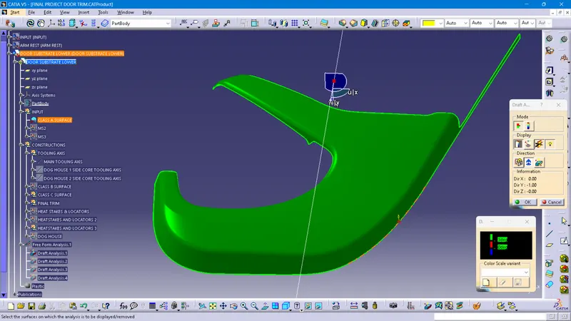
All the areas of the class A surface is perfectly satisfying the draft angle of 3 degrees wuth the tooling axis.
Map pocket: In this part also, y direction is selected as the main tooling direction. An axis is created in this direction. Draft analysis is conducted on the Class A surface with this tooling axis. Screenshot is given below.
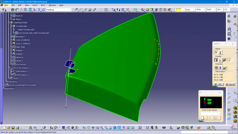
All the areas of the class A surface is perfectly satisfying the draft angle of 3 degrees wuth the tooling axis.
Bottle Holder: In this part also, y direction is selected as the main tooling direction. An axis is created in this direction. Draft analysis is conducted on the Class A surface with this tooling axis. Screenshot is given below.
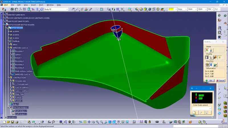
As seen in the screenshot, some of the areas of the surface doesn't satisfy the draft angle of 3 degrees. But it is not possible with the given class A surface to create a tooling axis that satisfy all the surface. As all other neighbouring parts satisfy draft analysis, with y direction, we can request the stylist who create the class A surface to improve the surface so that these areas give 3 digree deviation in y-direction. But as this is not possible here, the project is proceeded with the same surface and y direction as tooling direction.
Class A surface improvement
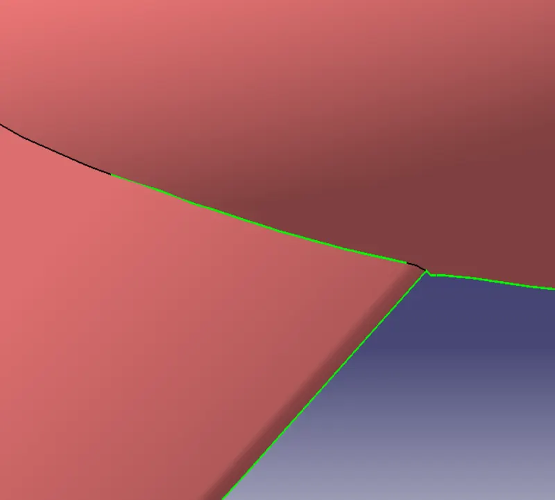
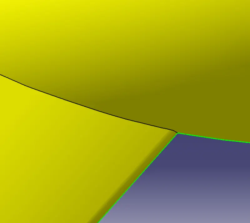
The given surface have some patches. As they create problem while making the closed body they are cleared and improved class A is used.
Closed Surface Creation
The body is thickened by creating closed surface with the class A surface and creating the closed body.
Class B surface creation:
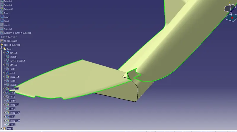
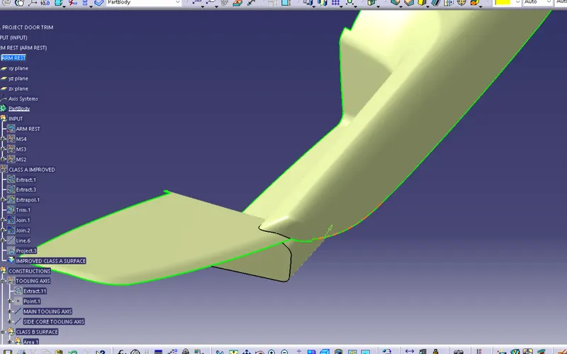
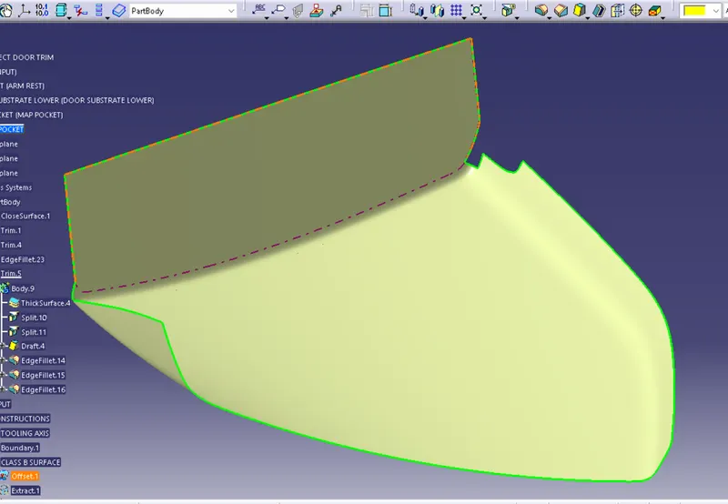
THe class A surface is offsetted by 2.5 mm which is the thickness of the body. Some areas of the offsetted surface are missing. They are filled with tools like multiple extract, extrapolate, trim join and multisection.
Arm rest:
Map Pocket:
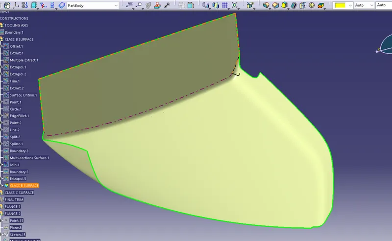
Class C Surface Creation: Class C surface is created by extracting the boundaries of class A surface, and sweeping with a draft angle of 3 degrees with the tooling axis. On boundaries where it is not possible, it is swept perpendicular to the class A surface.
Closed Surface Creation : The class A surface is joined with the class C surface. It is then trimmed with the class B surface tocreate the closed surface.
Engineering Feature creation
The engineering features such as heat stakes and locators are created in the B side of the parts following the design rules and master section given.
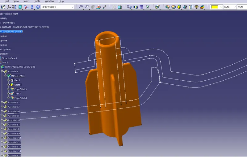
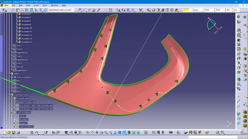
The features created translated to points where the stress might act. Heatstakes are created on points considering the accessibility of the staking machine
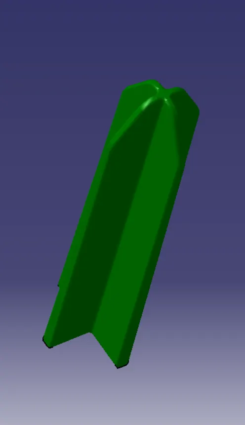
Dog Houses are also created with slots for push clips. They are given ribs for strength and drafted along tooling direction. Side core axis is created for each doghouse.
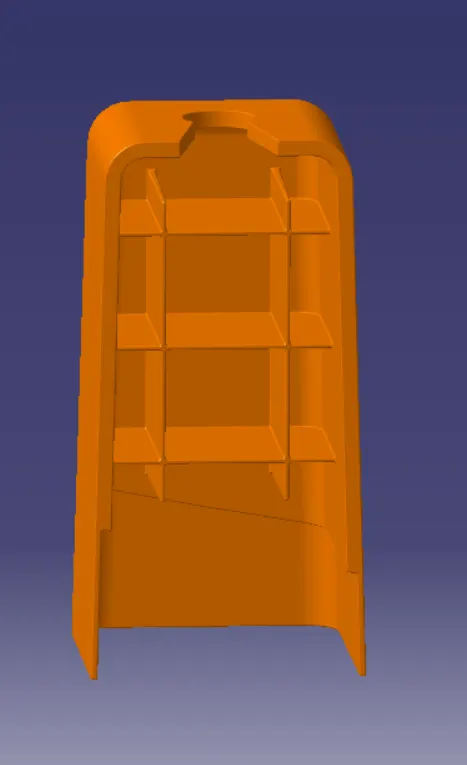
All the engineering features are trimmed with the main part body.
Flange Creation :
Flange are also created following the master section. The surface of the flange is created and part is made using thicken tool. Flanges are also given 3 degrees draft with main tooling axis.
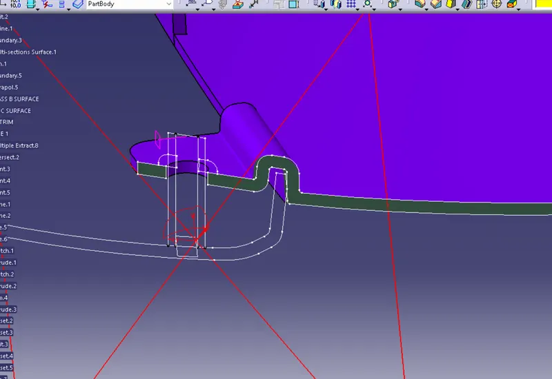
Finally flanges are trimmed with the main body.
Draft analysis B engineering features
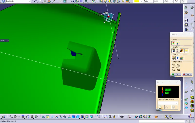
The outer surface of the doghouse satisfies 1.5 degree draft with main tooling axis.
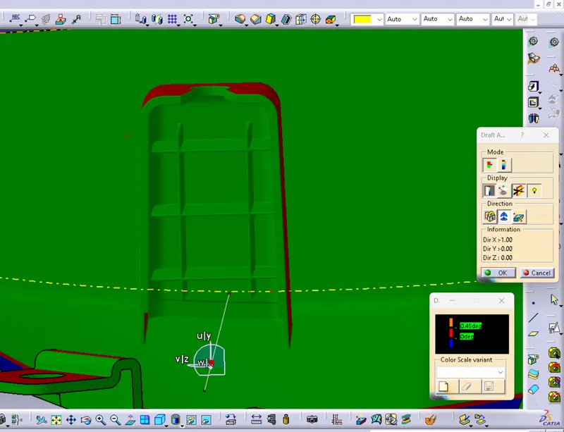
Inner surface of the doghouse satisfies 0.5 degree draft with the side core tooling axis created.
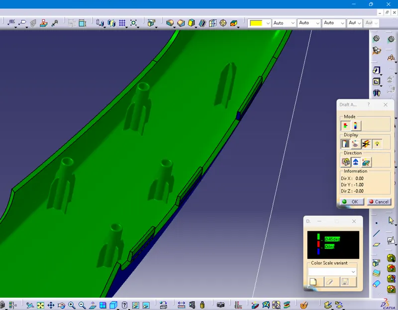
Heat stakes and locators satisfies 0.5 degrees draft with the main tooling axis.
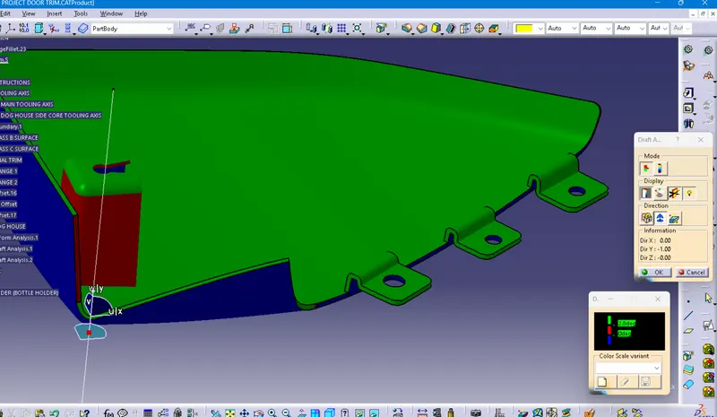
Flanges satisfies 3 digree draft with main tooling axis
Assembling push clip
The push clip is then assembled to the doghouse
The parts are given plastic material.
Final Door Trim Assembly