Week 11 - Final project
Aim:
To create a complete solid body of the inner door panel from the given Class A surfraces. Main substrate ( Lower substrate ),Door arm rest , Map pocket and Bottle Holder are the A surfaces given to us and these are the parts that requires to be convertred into solid bodies and assemble them along with the attachment features.
INTRODUCTION :
The door panel is the interface between the interior of the car and inner working of the door. Generally, the door panel is divided into parts for easy designing like arm rest, map pocket, Lower substrate
A) CLASS A SURFACE OF A DOOR PANEL
Door Panel class A surface has the following parts -
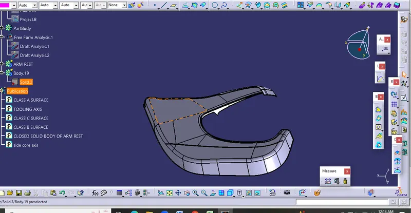
- Door Arm Rest
- Lower Substr
- Map Pocket
- Bottle Holder
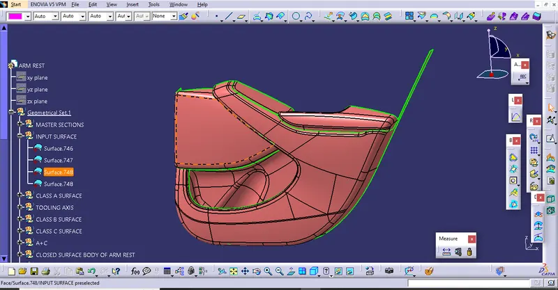
1. Door Arm Rest
• Creation of tooling axis
The line has been created using the line command. The point-direction option is used to create the main tooling axis in the z-direction.
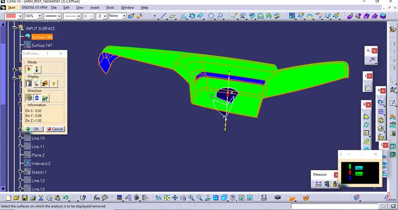
• Creation of Class B surface
Class B surface has been created by offsetting of class A surface. Offsetting has been done using the offset command. Class A surface is offset with a 2.5 mm distance. Surfaces that were not offsetting were formed using the multisection command.
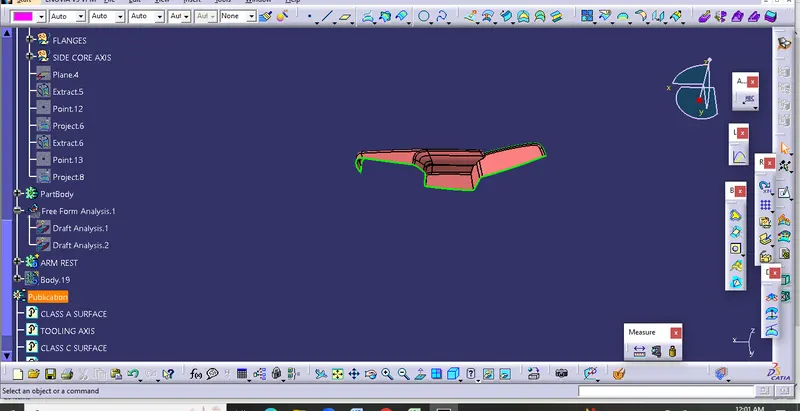
• Creation of Class C surface
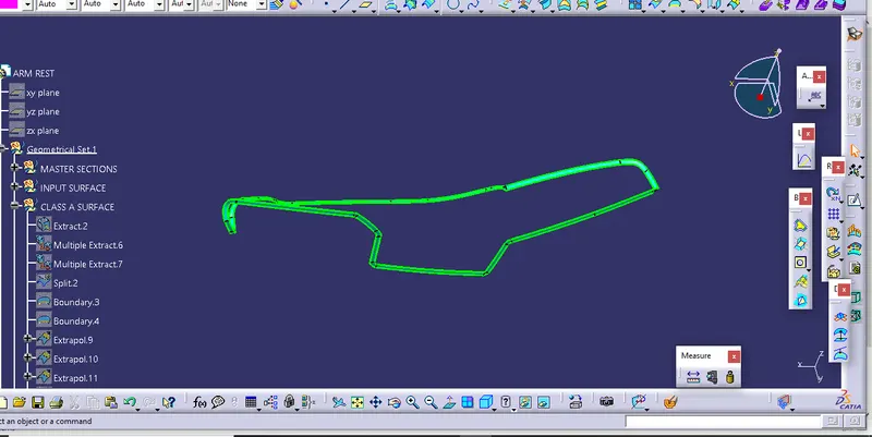
Using the Multiple extract commands, boundaries of class A surface were extracted. Class C surface joins class A and class B surfaces. It is created using the sweep command. Inputs for the sweep command were extracted boundary, class-A surface, angle value, and length of the sweep. Due to surface irregularities, it was not possible to create a single sweep. Hence, several sweeps and multisection were created, and finally, they joined together to create a class C surface.
CLASS A B C SURFACE JOIN AND SOLID BODY
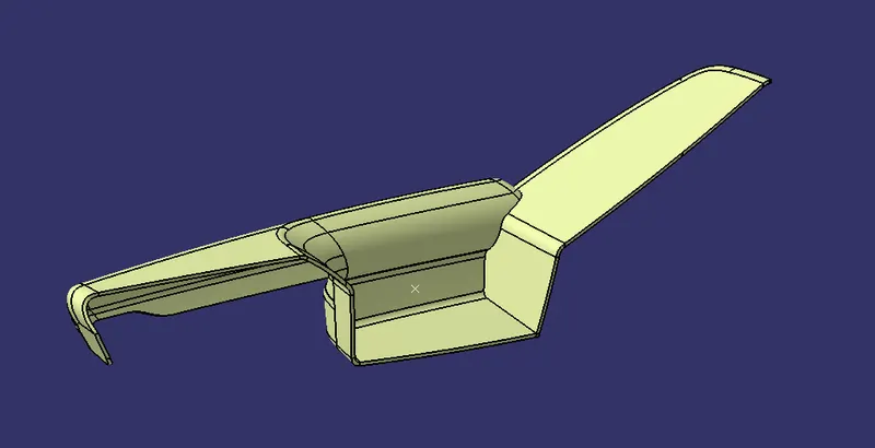
- Trim the obtained surface with Class B surface.
- Make Slight Adjustments by extrapolating small values and trimming to obtain a final Enclosed Surface.
2.LOWER SUBSTRATE
CLASS A SURFACE
Creation of tooling axis
The line has been created using the line command. The point-direction option is used to create the main tooling axis in the Y-direction.
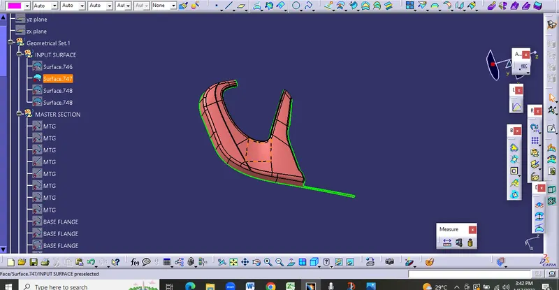
• Creation of Class B surface
Class B surface has been created by offsetting of class A surface. Offsetting has been done using the offset command. Class A surface is offset with a 2.5 mm distance.
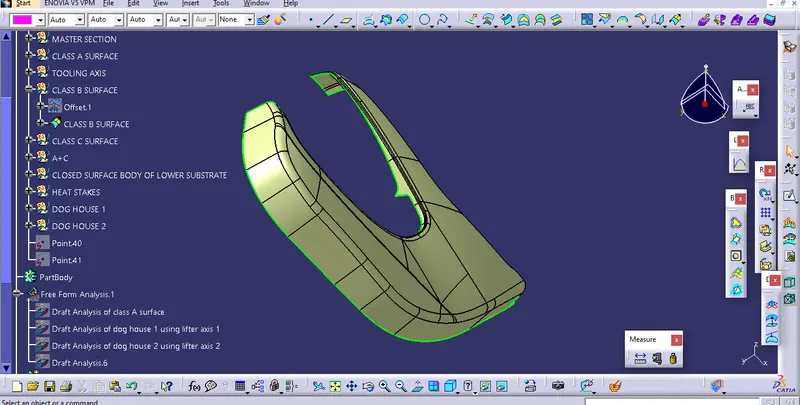
Creation of Class C surface
Using the Multiple extract commands, boundaries of class A surface were extracted. Class C surface joins class A and class B surfaces. It is created using the sweep command. Inputs for the sweep command were extracted boundary, class-A surface, angle value, and length of the sweep.
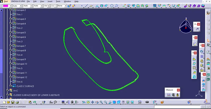
CLASS A B C SURFACE JOIN AND SOLID BODY
- Trim the obtained surface with Class B surface.
- Make Slight Adjustments by extrapolating small values and trimming to obtain a final Enclosed Surface.
3. INNER MAP POCKET
Creating class a surface
Extract input surface
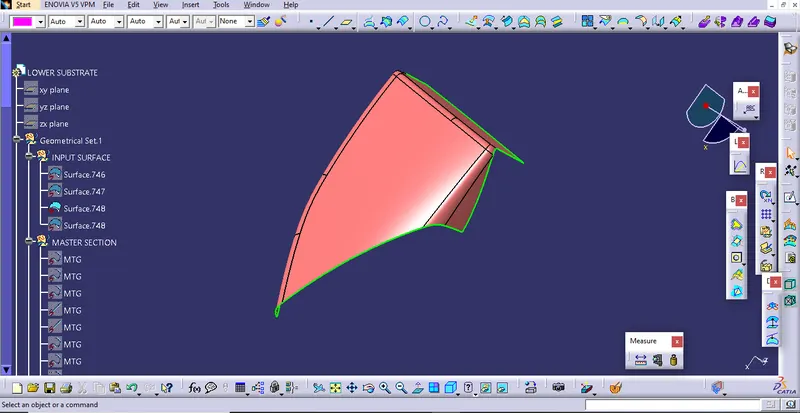
Creation of Class B surface
Class B surface has been created by offsetting of class A surface. Offsetting has been done using the offset command. Class A surface is offset with a 2.5 mm distance. Surfaces that were not offsetting were formed using the multisection command.
• Creation of Class C surface
Using the Multiple extract commands, boundaries of class A surface were extracted. Class C surface joins class A and class B surfaces. It is created using the sweep command. Inputs for the sweep command were extracted boundary, class-A surface, angle value, and length of the sweep.
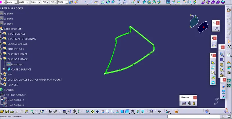
CLASS A B C SURFACE JOIN AND SOLID BODY
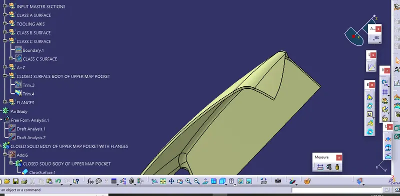
INNER map pocket
CREATING CLASS A SURFACE
Extract input
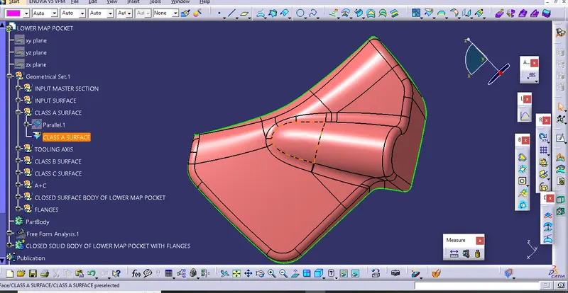
• Creation of tooling axis
The line has been created using the line command. The point-direction option is used to create the main tooling axis in the y-direction.
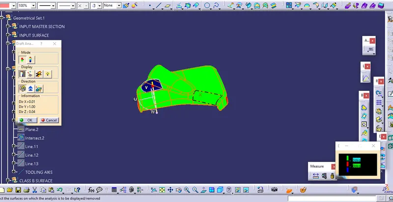
Creation of Class B surface
Class B surface has been created by offsetting of class A surface. Offsetting has been done using the offset command. Class A surface is offset with a 2.5 mm distance.
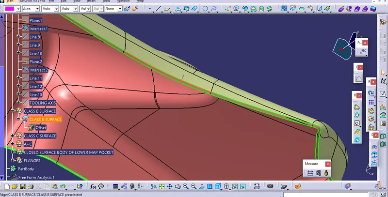
CLASS A B AND C SURFACE
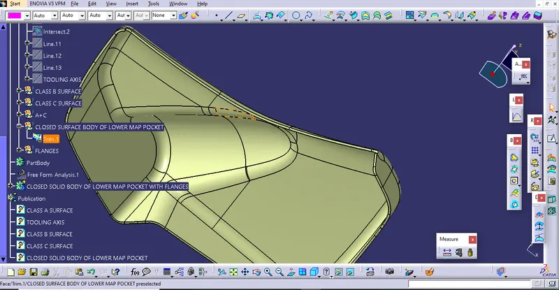
The join of Class A and Class C surface is trimmed with class B surface to create a closed surface.Above Close surface is converted into the close body using the close surface command from part design workbench.
FLANGE HEAT STEEKS & DOGHOUSE
FLANGES-
Flanges are the elements that are needed to join different components together. So here I have to make flanges on the door armrest and the map pocket. Following the master section, given as the input basically the measurements and location of the flange. I have created t he flanges. First I have created the flange on the outer map pocket. For creating the flanges I have taken extraction of the curve and made a point on that curve then created one plane on that point followed by creating a sketch on that plane taking the point created as the origin.
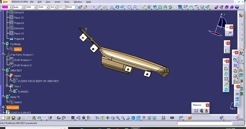
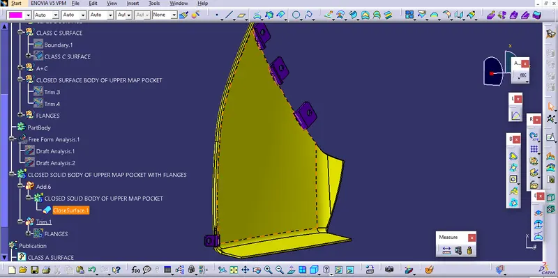
After creating the flanges I have created the dog house.
Dog House
-Dog house is an engineering feature used in the plastic trim design. Doghouses are used as supporting features. Sometimes other engineering features like snaps; locators, etc. are mounded on them to increase their strength. Dog houses are subjected to draft analysis to prevent breakage of the component during ejection from the mold cavity. Dog house and other engineering components are built on B-surface.
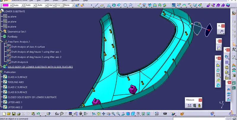
Here the dog house is required for lower substrate only. So for creating the dog house I have extracted the base surface of the lower substrate and made a point that extracted surface and sketched on it.Then I have swept the above sketch along the tooling axis of the lower substrate giving 1.5 degrees of the draft Then I have closed the surface on the top. After closing the surface I have used the thick surface command to make a solid body giving 2mm thickness.For this purpose, I have just offset the base of the lower substrate to a height of 4mm the value could be anything between 3-6mm and then I have extracted the inside portion of the dog house.Then I have extrapolated the inside portion that extracted and trimmed it with the base which saran offict of 4mm
PUSH PIN
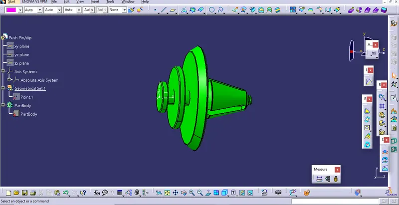
Push pins-Push pins are used for joining one component to another. These are basically attached to the dog houte For creating the push pins I have taken the following reference basically the measurements
CONCLUSION
The door Panel has been successfully designed by following OEM standards used in Automotive Industry. All the attachment features are properly placed at different locations he designed part meets all the defined objectives.