Week 11 - Final project
DESIGN OF DOOR TRIM PANEL
DOOR PANEL
The door panel covers internal parts like the window regulator, the power window motor, and the wiring. It is attached to the sheet metal part of the door. It is designed differently based on the design of the sheet metal part of the door. Besides its aesthetic look, it also has many functional features attached to it such as an armrest, bottle holder, speaker attachment, etc. In older cars, door panels used to be made out of cardboard and upholstered with material that matches the rest of the upholstery within the cabin. On the other hand, most modern cars have door panels made from plastic. The main materials used include kenaf, which grows year-round and has excellent CO2 absorbing properties, and plant-derived plastic, making them environmentally friendly as well.
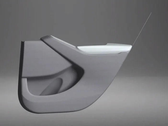
DESIGNED DOOR TRIM PANEL (RENDERED)
Aim:
To Design a part of the Car door Plastic components placed in the car door panel by following the design standards used in the Industries using Catia v5 software with the provided class A surface
Abstract:
The project report contains the steps and procedures followed while developing plastic door trim panel from the class A surface provided.It contains the method followed for creating the tooling axis, Class B surface, Class C surface, and final closed body creations. Also explains the draft analysis performed to check the manufacturability of the products using injection moulding.
APPROACH:
The basic approach to make a plastic model from class-A surface is:
- Make tooling axis
- Run draft analysis
- Make class B surface
- Make class C surface
- Trim all together and make it solid.
CLASS-A SURFACE
Class ‘A’ surfaces are primarily used in the automotive environment and refer to those surfaces which are visible in a product. In other words: A - class surfaces are those aesthetic/free-form surfaces, which are visible to us (interior/exterior), and have an optimal aesthetic shape and high surface quality.
Here, one should understand the difference between the internal or external and visible or hidden surface. The surfaces or regions which are visible nowadays are considered for Class-A modelling. It is one of the reasons why the importance of Class-A modelling is increasing day by day. Majority of the time this term is used in Plastic Part designs.
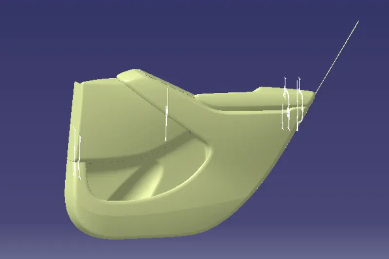
GIVEN CLASS S SURFACE WITH MASTER SECTION
MASTER SECTIONS
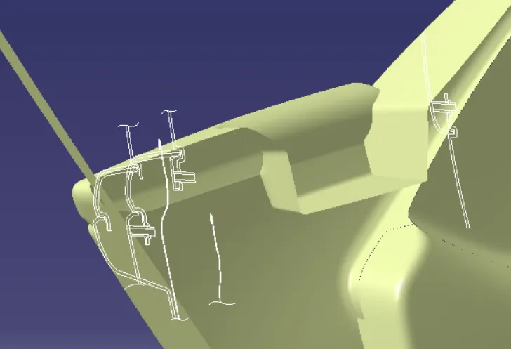
These are the guidelines provided to a design engineer which describe how a component would/must look like once it is modeled into a solid component from the class-A surface. For example, in this model, we have received a master-section as an input which tells us about the thickness of the component and dimensions & type of the engineering features on the component.
TOOLING AXIS
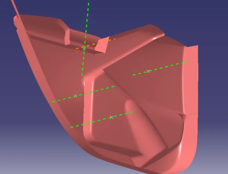
Tooling axis is the axis along which the core and cavity opens and closes. It is very important to define the tooling axis in the first step while designing a component as it is the main component which helps us to run draft analysis on class-A at initial stage to see if we can move ahead. Also for later stage, tooling axis is the direction along which class-C surface and the draft to the components is given.
For the creation of tooling axis there are different methords one is the Bisecting Line methord for this a suitable surface is chosen. A point is placed on the middle of that surface for creation of an axis system. A Point sketch is added on Axis system so as to intersect the surface and an intersection of the surface is made on the surface. lines which seems to create problems in the moulding are noted and an impression of it is made on the sketch and a bisecting line of the same is made. Now repeating the same procedure on the othher perpendicula plane could give you another bisecting line. Now a bisecting line of the two lines obtained is created which will be our tooling axis. Another methord is by choosing a suitble direction on a surface by visual analysis and doing the draft analysis for verification, this is a trial and error method
DRAFT ANALYSIS
Our first step before starting the model should always be to check is the surface has enough draft that it will not create any problems while ejecting from the mold considering the tooling axis. Some components require side core where there are under undercuts, holes or projections on the side walls, so for this we need a different tooling axis and a different analysis is required to check those areas. Draft analysis shows color codes which are defined by the user for different values which are also userdefined. These colors help us to analysis if the component is clearing. In case the component fails the analysis for class-A then we have to submit the draft analysis report to the higher authority so that the surface of the component can be improved. Failing analysis simply means that the component does not have the required draft value it must have. We have to make sure that our entire model is clearing the analysis. So we have to run analysis for class-A, solid model and other B-side features as every single component, regardless of its size should be ejected safely from the core.
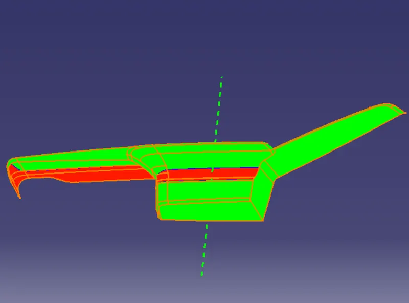
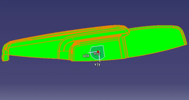
DRAFT ANALYSIS OF ARM REST (CLASS A AND FINAL PRODUCT)
The class A surface is not clearing for the draft analysis done. The design will cost the manufacturer a larger amount to create this part.
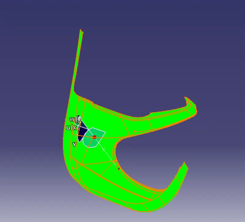
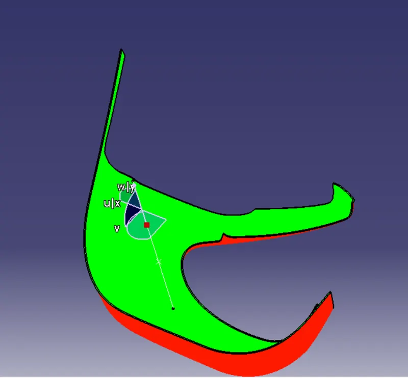
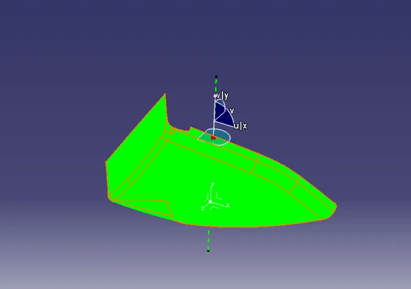
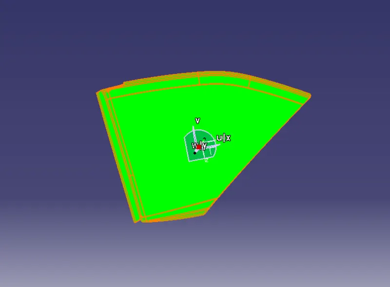
DRAFT ANALYSIS OF LOWER SUBSTRATE (CLASS A AND FINAL PRODUCT)
Both the class A and the part is clearing the draft analysis
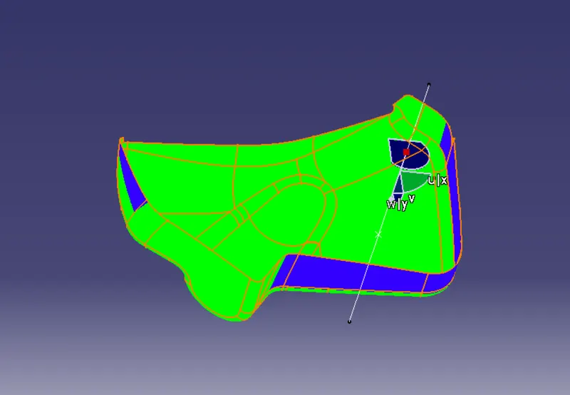
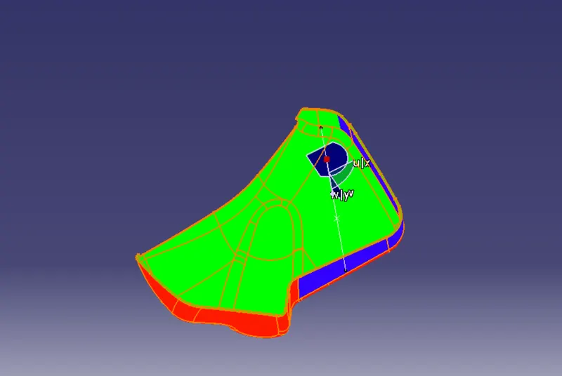
DRAFT ANALYSIS OF UPPER MAP POCKET (CLASS A AND FINAL PRODUCT)
Both class A and the Part is clearing the draft analysis
DRAFT ANALYSIS OF LOWER MAP HOLDER (CLASS A AND FINAL PRODUCT)
Both class A and the Part is clearing the draft analysis
PROCEDURE
The first procedure is to check whether the provided class a is of good quality or not, for that we check the boundary of the given class A surface if it shows some boundaries otherthan the desired ones we have to clear for the arm rest there was a certain problem with the quality of the class A
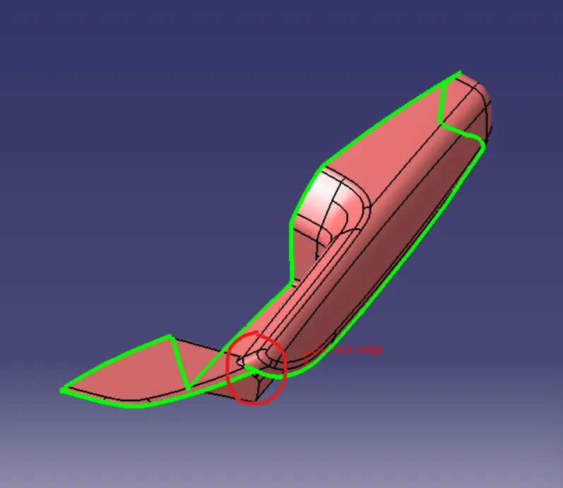
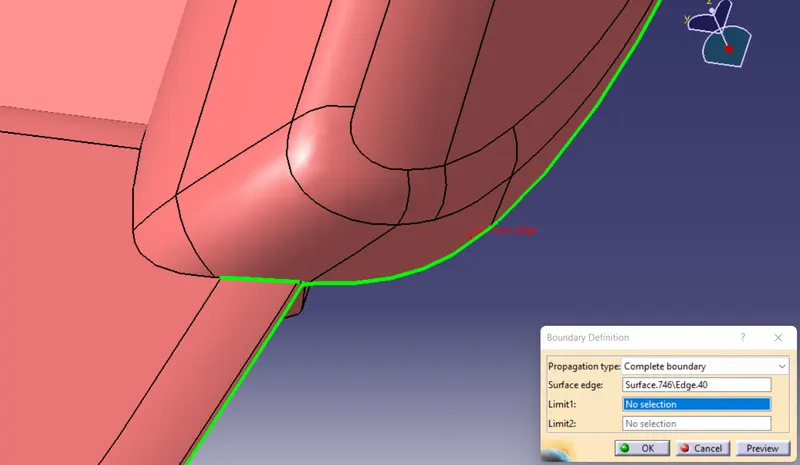
CLASS A QUALITY ISSUE
This issue was resolved by extract extrapolate and trim commands
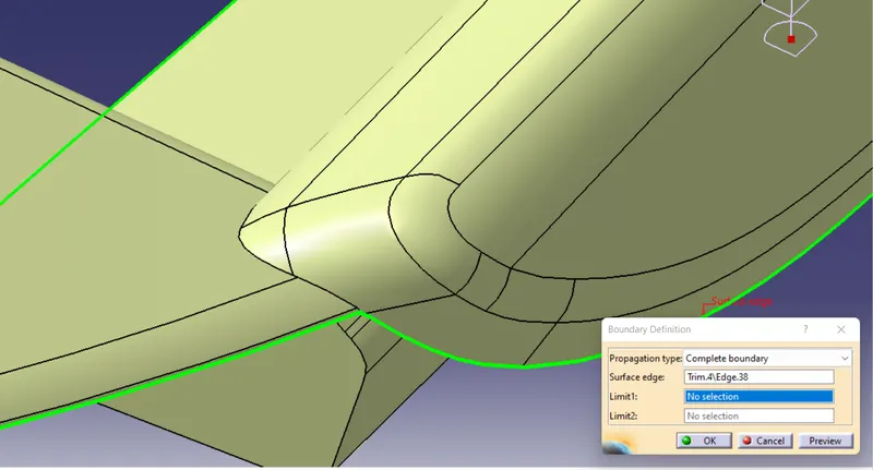
ISSUE RESOLVED CLASS A
The next procedure to follow is the
Tooling axis creation and the
Draft analysis
After that we create the
CLASS B surfaces
For that first Offset the A-surface for 2.5mm(according to master-section) and work on the patches if any are required.
Certain patches where missing while offsetting most of the surfaces so several procedures were done within the industrial rules and norms to obtain a fine CLASS B surface
ARM REST
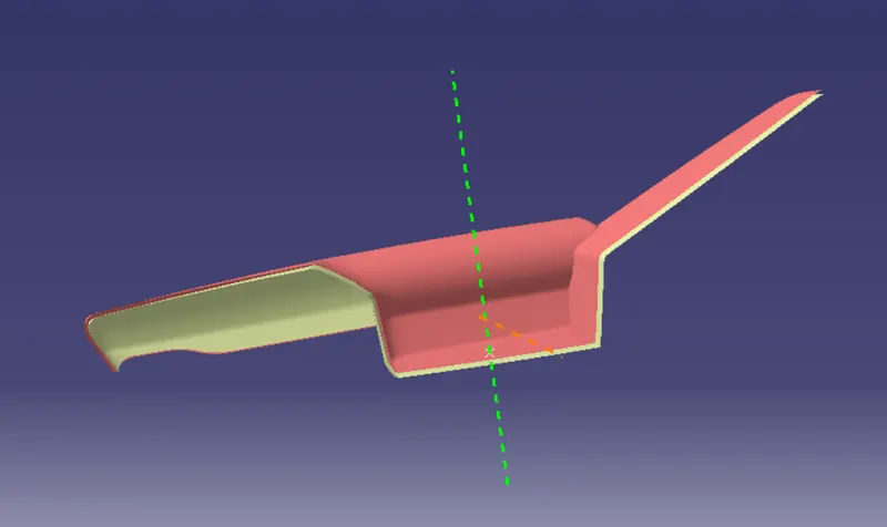
The one in the top (coloured) is the class A surface and the other one is class B surface
LOWER SUBSTRATE
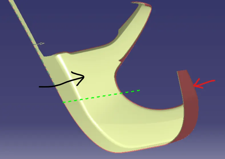
The one marked in black is the class A surface and the other one marked in red is class B surface
UPPER MAP POCKET
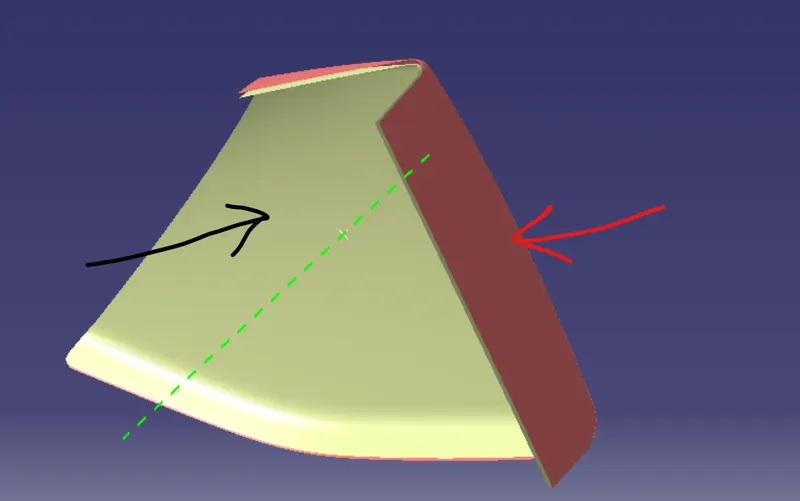
LOWER MAP HOLDER
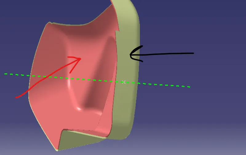
he one marked in black is the class A surface and the other one marked in red is class B surface
CLASS C SURFACES
Class C surface is created by sweeping along the boundary of the class A surface wihe the desired draft angle. For the patches in class C surface multi section command iss used
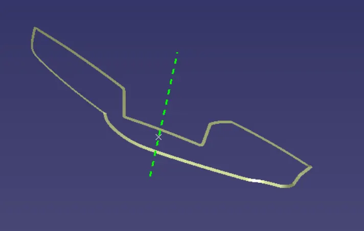
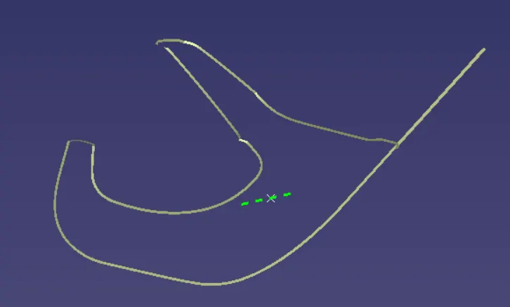
ARM REST AND LOWER SUBSTRATE
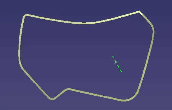
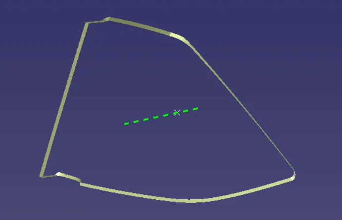
LOWER MAP HOLDER AND UPPER MAP POCKET
JOINING AND TRIMMING TO CREATE A SOLID
The next procedure is to join the surfaces togeather and creating a closed component for that we trim the A and C surfaces first and then trim the result with the B surface as a result we get a closed componentwhich is then converted to a solid part using CLOSE SUFACE COMMAND
ADDING ENGINEERING FEATURES TO THE BODY
The next procedure to be followed is adding engineering features to the created part the features added are
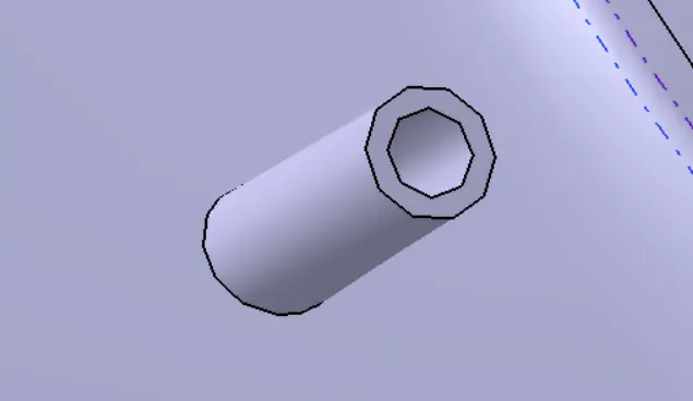
1. HEAT STAKES
Heat Staking is a pulsed-heat process to join two or more parts out of which one at least is made of plastic. The process is to deform the plastic material using heat and force at a set process time. The bond is made by partially de-forming the plastic part in order to fix the other.
Heat stakes are created on Lower-substrate wherever the flanges are projected on the lower-substrate.
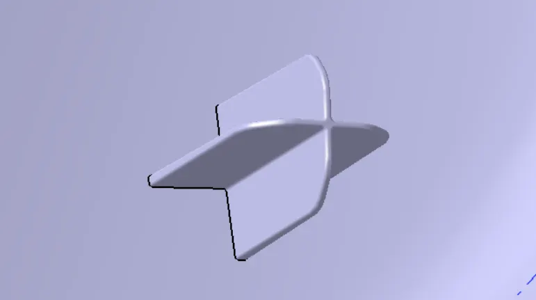
2. LOCATORS
Locators are the small projections place on a plastic part which helps in the proper alignment and arresting of the components for fixation. There shall be a hole in the mating part so as the locator slides inside and fits in properly with the other part
Here we have used 4 way locators
DESIGN RULES FOR LOCATORS:
- Draft: 0.5 deg per side (minimum), but this value should not be high enough that it will cause failure for other consideration. For example, more draft will result in less thickness at the top surface.
- Thickness: 40% of wall thickness or 0.4*t where t is the wall thickness.
- Height: Varies according to the component
3. PUSH CLIPS
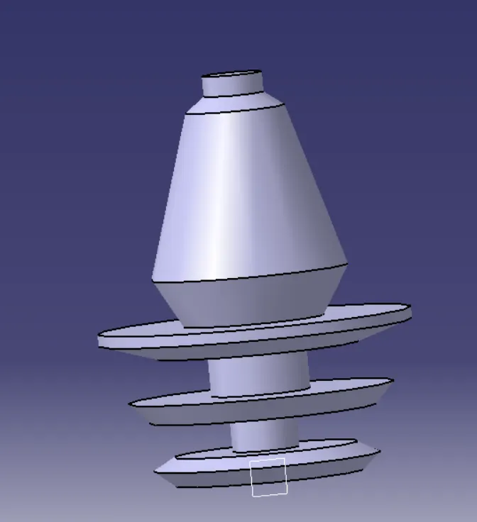
Push clips are fixing cmponents mount on dog house which help in clipping the part to the other body. As the push clips are manufactured else where and is not in our zone of concern so we have ignored the rules while making the push clips and made a general clip of similar shape in part design without following any rules.
3.DOG HOUSE
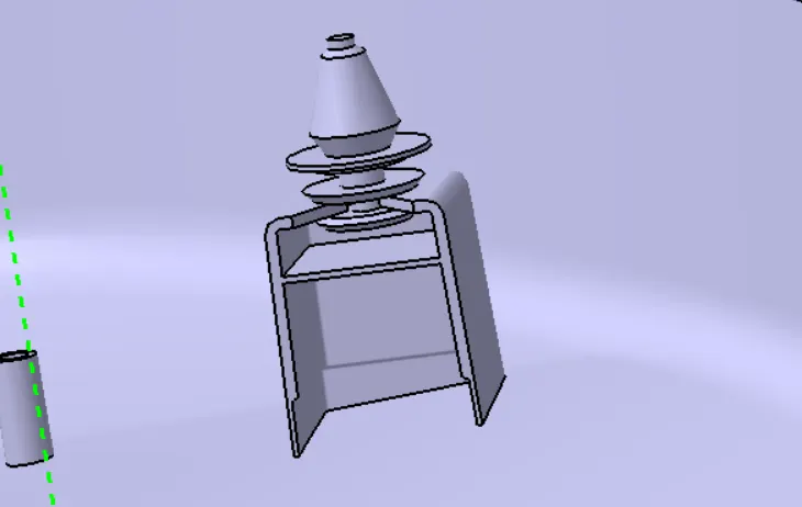
Primary function of the dog house is to avoid sink marks. But it also helps in other things like if the mating part is to be at a greater distance then we cannot make the height of the screw boss of that greater height, thus we make dog house and mount screw boss on it. Hence it helps in solving the problem of screw boss and also it helps to have perpendicular screw boss.
GENERAL DESIGN GUIDELINES FOR DOG HOUSE DESIGN:
- Minimum height: Less than 6mm causes steel condition.
- 3:1 ratio of steel width to height. But 2:1 is preferred.
- Minimum width: 3:1 ratio of steel width to height. But 2:1 is preferred.
- Draft: minimum 1.5deg.
- Sink saver: height= 40% of nominal thickness. Width= 3.0mm-6.0mm.
- Optimal radius:25mm
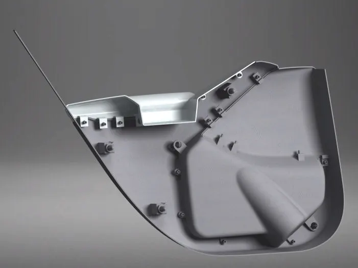
FINAL COMPONENTS WITH ENGINEERING FEATURES
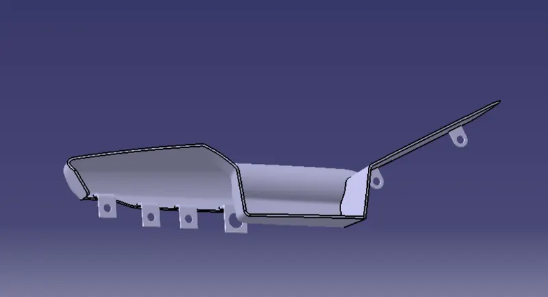
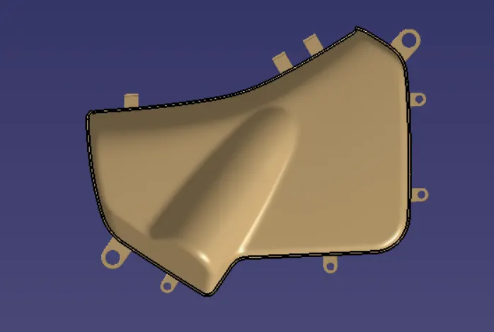
ARM REST
LOWER MAP HOLDER
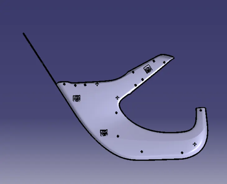
LOWER SUBSTRATE
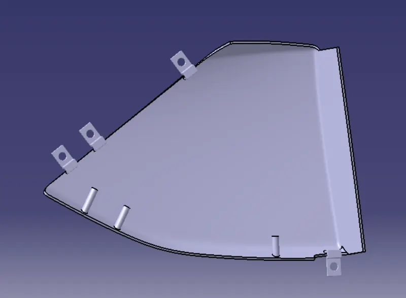
UPPER MAP POCKET
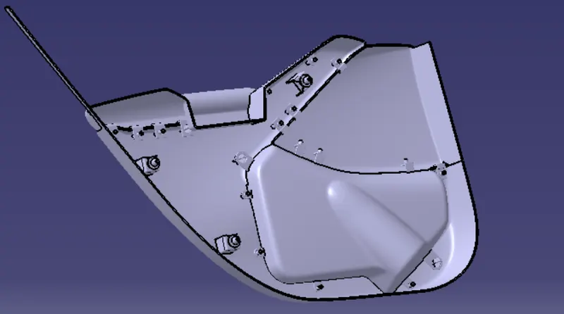
OVERALL 3 LOCATORS, 3 DOG HOUSE AND 16 LOCATORS ARE PROVIDED FOR FIXATION
FINAL COMPONENT
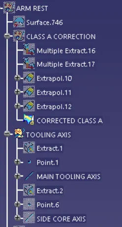
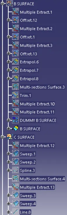
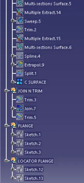
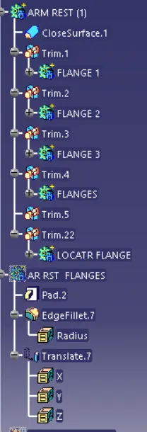
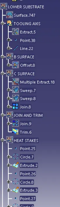
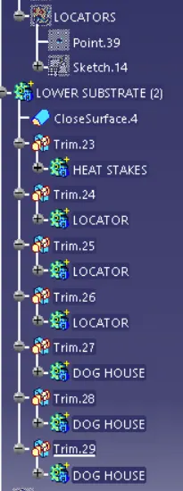
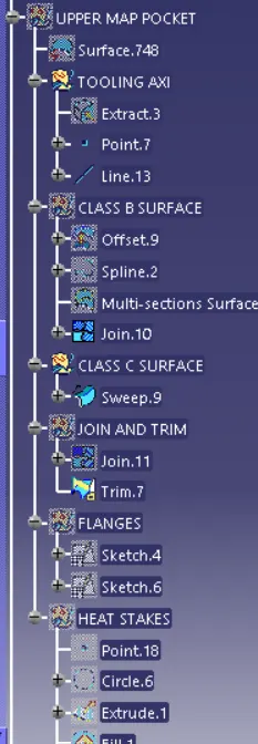
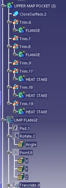
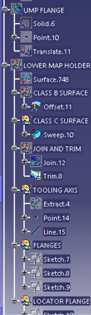
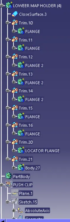
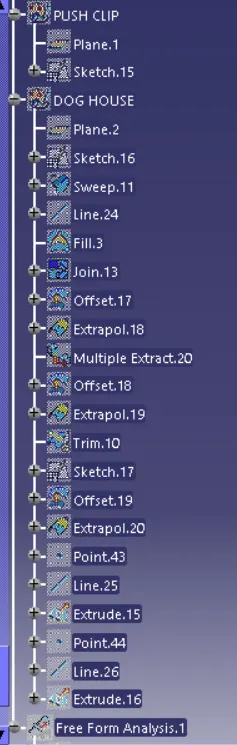
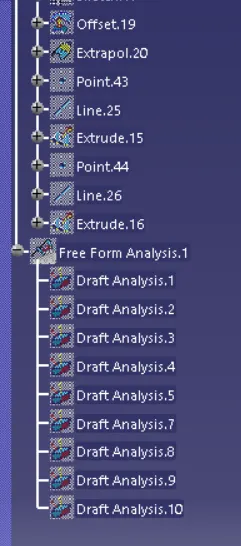
TREE STRUCTURE for above:
CONCLUSION:
The door trim panel was successfully created with all the design rules taken into considerations for feature attachment and the main part was created using the master section provided with the input class A.