Week 11 - Final project
Design & Development of Door Trim Panel
Introduction:
- An internal part linked to the inner side of the door is called a door trim panel. This item does more than just make the interior of the car seem nicer.
- Instead, it is a crucial module component that adds a range of amenities and features to make the interior more pleasant. As a result, there is a need to balance the gaps between the various sections and create a sense of general harmony among them.
- They must adhere to a number of design requirements in terms of operation, appearance, and safety.
- Currently, doors have an interior full-width panel that includes speakers, an armrest, a map pocket, a bottle holder, and electronic windows.
- These panels typically have a foamed core that is wrapped in either plastic or fabric.
- The main goal of this project is to create plastic door panel material for door trim components that comply with OEM standards.
- The Correct Tree Structure should be followed using a boolean operation.
- The name of a geometric set should be based on proper Standards.
Aim:
- Creation of a CAD model taking into account the following inputs similar to OEM and Tier 1 businesses
a) Category A surface
b) Reference master sections for nominal thickness
c) Part-to-part attachment technique: Use heat stakes.
- To design a tooling axis that complies with the specifications for the draught angle for the specified Class-A Surface and then perform a draught analysis on the finished model.
- The Correct Tree Structure should be followed using a boolean operation.
- The name of a geometric set should be based on proper Standards.
Model of Door Trim Panel:
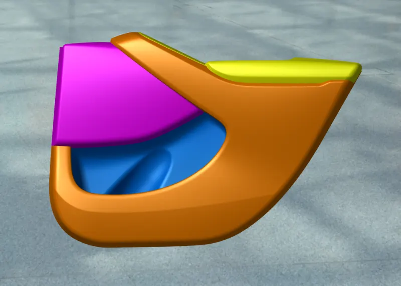
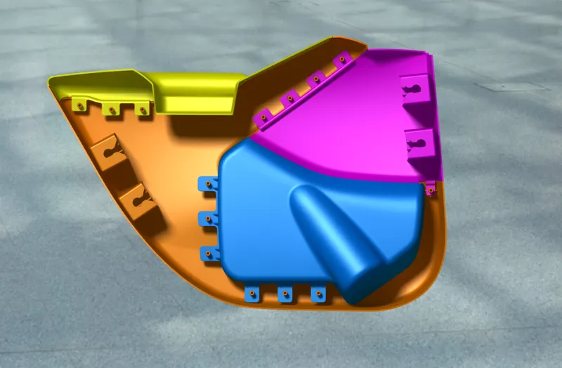
Arm_Rest:
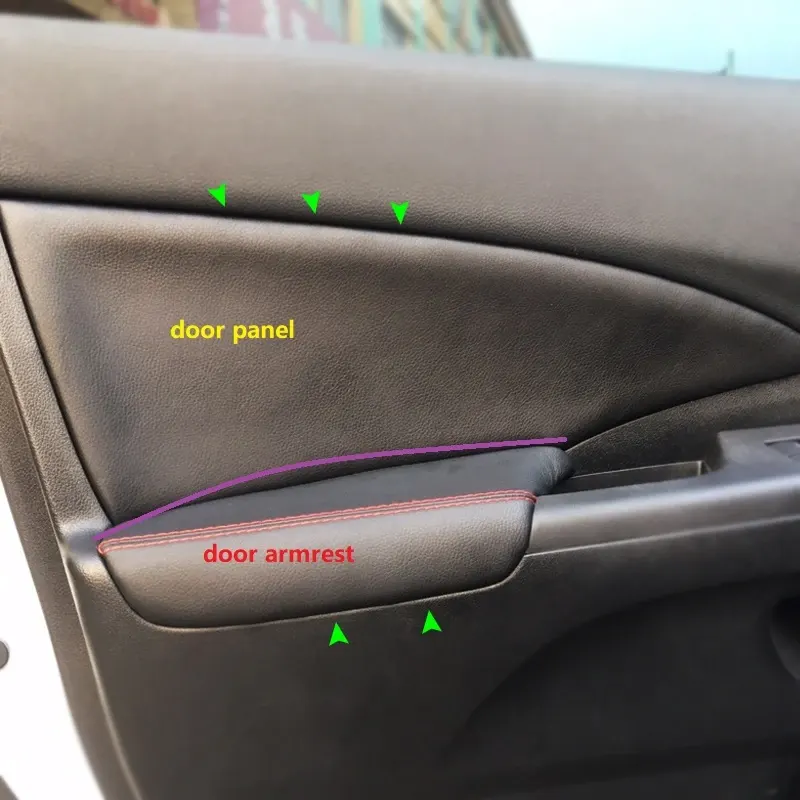
- The support that armrests offer for your hands and arms is highly beneficial.
- They will assist in directing your hands and arms into a relaxed position, releasing any muscle tension that would otherwise develop when they are not in the proper alignment.
Class.A_Surface:
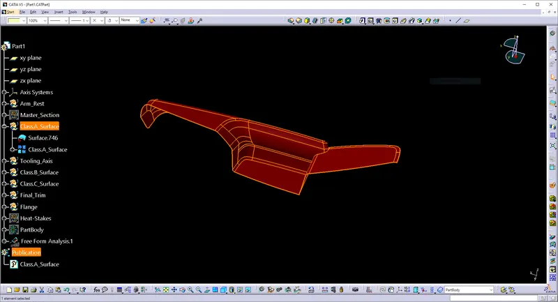
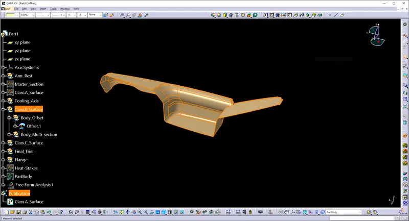
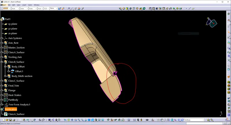
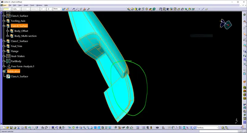
- Error Fixed
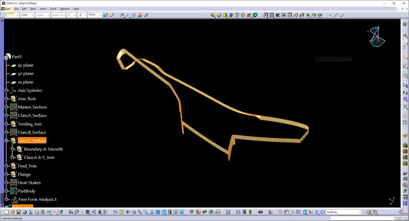
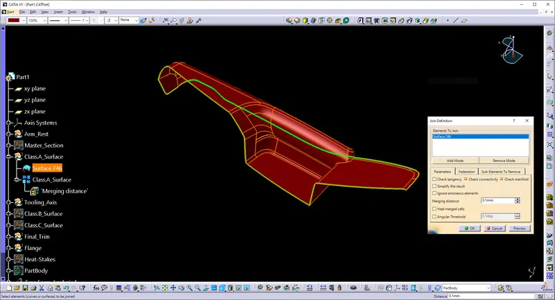
- In Class A surface, must be closed.
- If it is not closed or any invalid features are noticed the part will not going to generate.
- The part is fully constrained, already it's closed we need to proceed. I use the joining method for my Identification.
Creating of Tooling Axis:
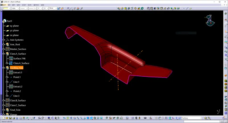
- Select Insert > Axis System from the menu bar or click Axis System . ...
- Select the point as shown to position the origin of the axis system you wish to create. ...
- If you are not satisfied with the x-axis, for instance, click the X-Axis field and select a line to define a new direction for the x-axis.
- Here we created 2-tooling Axis because of draft analysis didn't clear.
- In this Arm_Rest design, they create 2 operations to manufacture as slider & Lifter.
Class.A & Class.C_Joining:
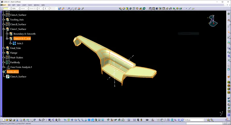
- In a process of joining A & C, it should be a closed surface.
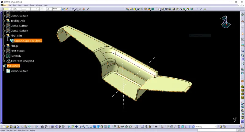
Class.A & Class.B & Class.C_Joining:
Draft Analysis:
- The draught analysis approach is used to determine whether our CAD-created part model is capable of being manufactured given the draught condition employed.
- Here, the component should be simple to remove from the panel dies (for sheet metal parts) or Mold (in plastic case).
Representation of the color range:
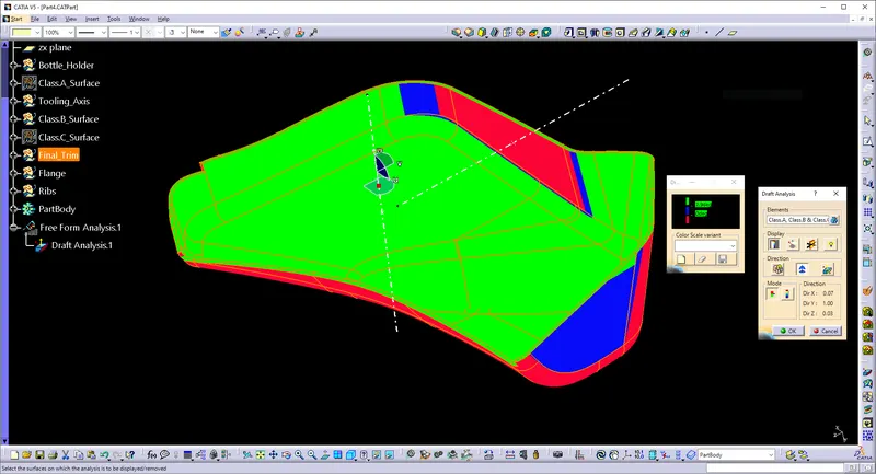
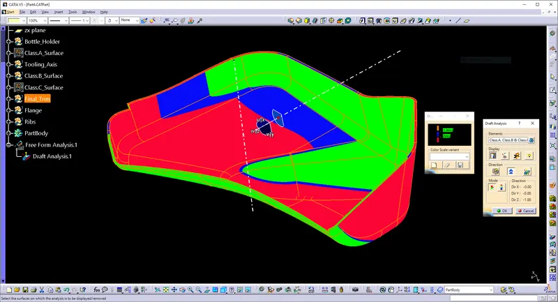
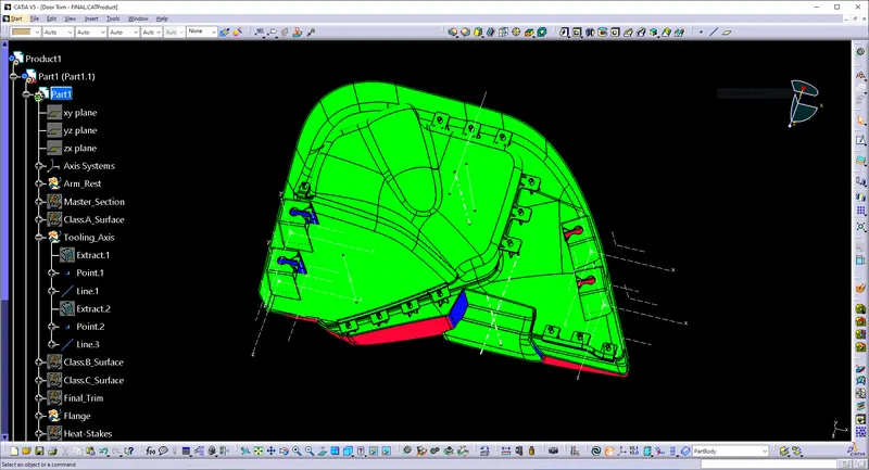
- Green color - Verify whether the draft meets your needs.
- Blue color - Determine the error.
- Red color - Make a distinction between the cavity and the core.
Draft Analysis on Class-A Surface:
- Enter analysis, feature draught analysis, and insert.
- Align the compass and the tooling axis.
- Click the surface to verify that it is within the draught values' permitted range.
- The surface should be green, and the nominal input value for the column should be 3 degrees.
- As a result, the draught analysis on the class-A surface was completed satisfactorily.
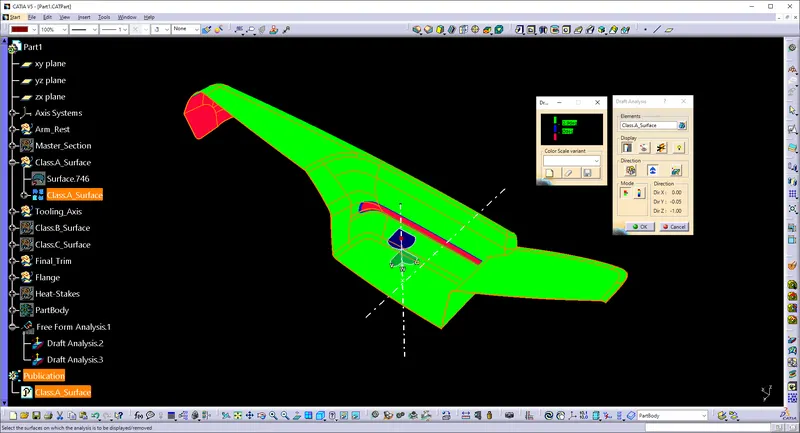
- Draft Analysis of Lifter as a Vertical Tooling Direction.
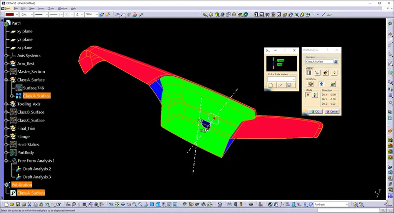
- Draft Analysis of Slider as a Horizontal Tooling Direction.
Draft Analysis on Final Part:
- Using the draught analysis command, you can determine whether the part you drafted will be simple to remove.
- In this kind of analysis, zones on the investigated element are identified by color ranges where the deviation from the draught direction at any given place corresponds to predetermined values.
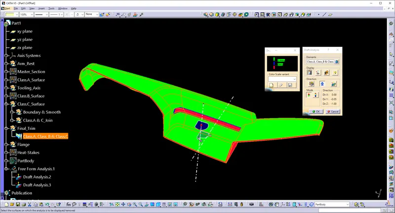
- Draft Analysis of Lifter.
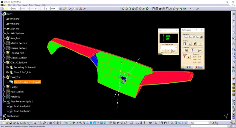
- Draft Analysis of Lifter.
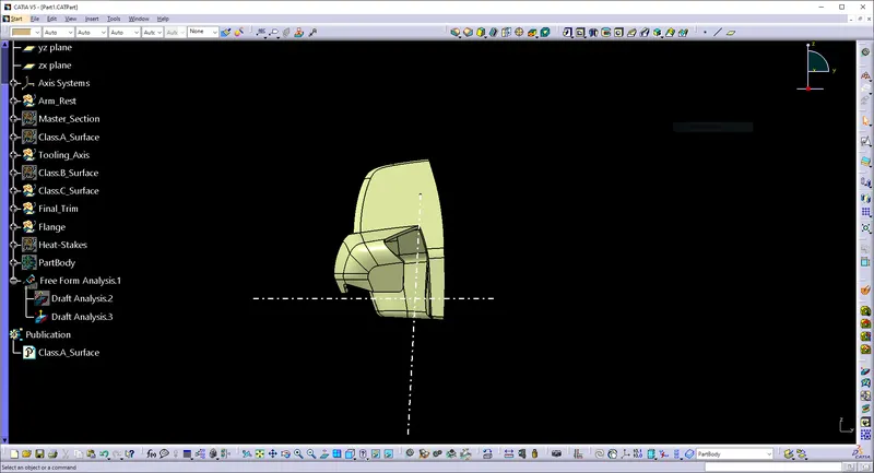
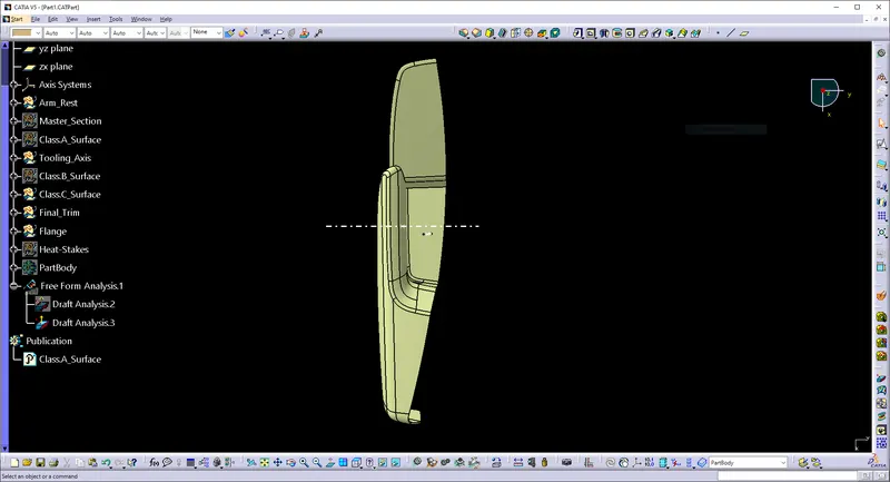
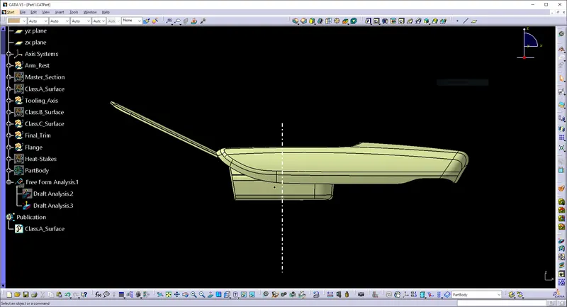
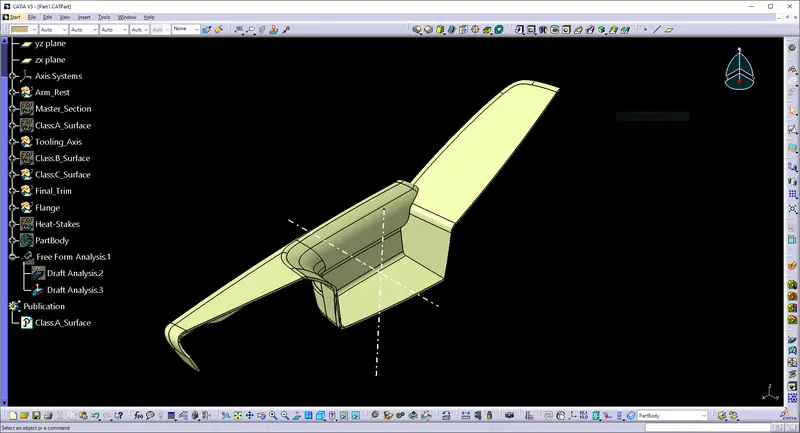
Orientation of Class A, B, & C, Surfaces:
Front View:
Top View:
Left View:
Isometric View:
Lower_Sub-Strate:
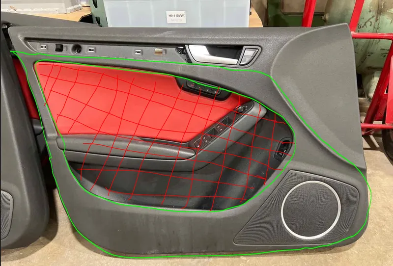
- The Lower substrate is present at the bottom portion of the door panel.
Class.A_Surface:
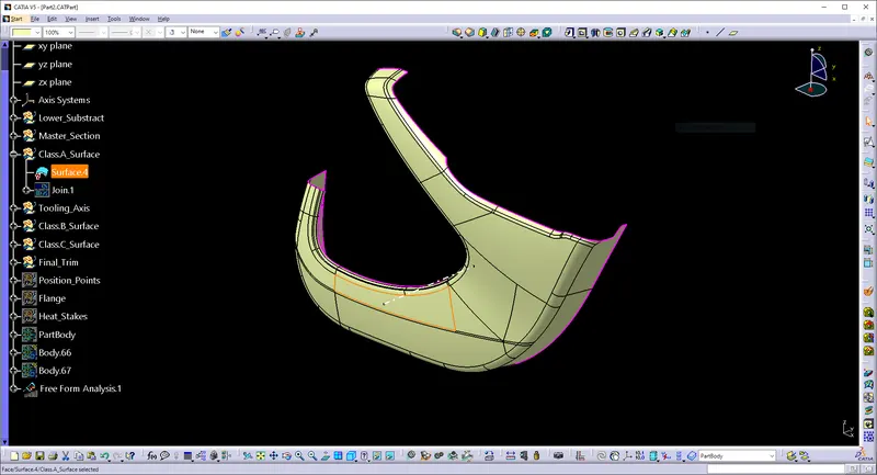
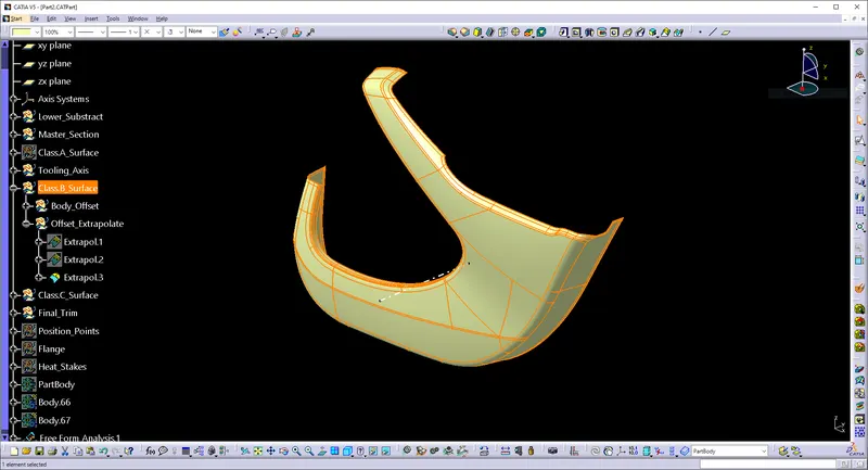
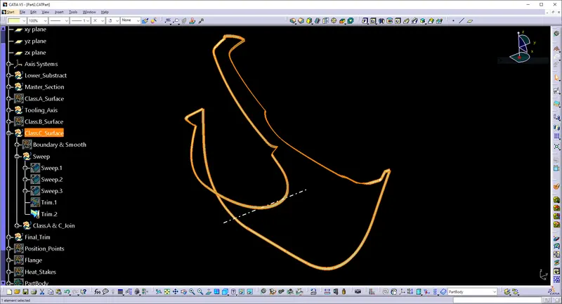
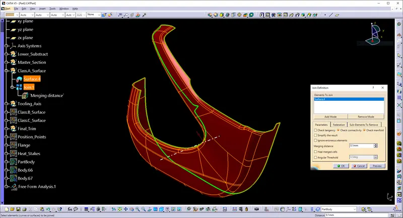
- In Class A surface, must be closed.
- If it is not closed or any invalid features are noticed the part will not going to generate.
- The part is fully constrained, already it's closed we need to proceed. I use the joining method for my Identification.
Creating of Tooling Axis:
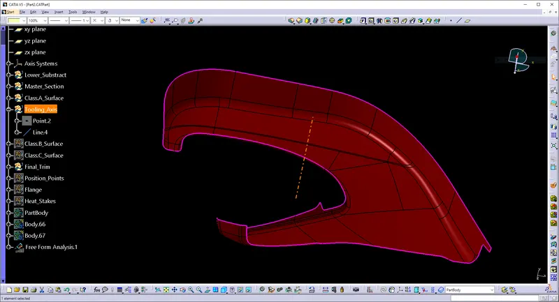
- Select Insert > Axis System from the menu bar or click Axis System . ...
- Select the point as shown to position the origin of the axis system you wish to create. ...
- If you are not satisfied with the x-axis, for instance, click the X-Axis field and select a line to define a new direction for the x-axis.
Class.A & Class.C_Joining:
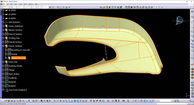
- In a process of joining A & C, it should be a closed surface.
Class.A & Class.B & Class.C_Joining:
Draft Analysis:
- The draught analysis approach is used to determine whether our CAD-created part model is capable of being manufactured given the draught condition employed.
- Here, the component should be simple to remove from the panel dies (for sheet metal parts) or Mold (in plastic case).
Representation of the color range:
- Green color - Verify whether the draft meets your needs.
- Blue color - Determine the error.
- Red color - Make a distinction between the cavity and the core.
Draft Analysis on Class-A Surface:
- Enter analysis, feature draught analysis, and insert.
- Align the compass and the tooling axis.
- Click the surface to verify that it is within the draught values' permitted range.
- The surface should be green, and the nominal input value for the column should be 3 degrees.
- As a result, the draught analysis on the class-A surface was completed satisfactorily.
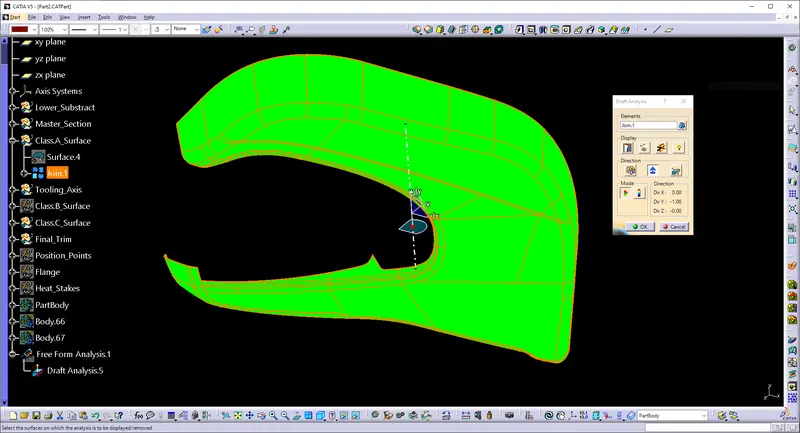
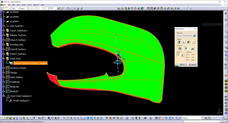
Draft Analysis on Final Part:
- Using the draught analysis command, you can determine whether the part you drafted will be simple to remove.
- In this kind of analysis, zones on the investigated element are identified by color ranges where the deviation from the draught direction at any given place corresponds to predetermined values.
Orientation of Class A, B, & C, Surfaces:
Front View:
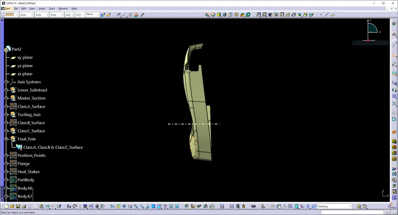
Top View:
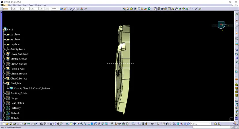
Left View:
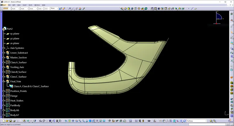
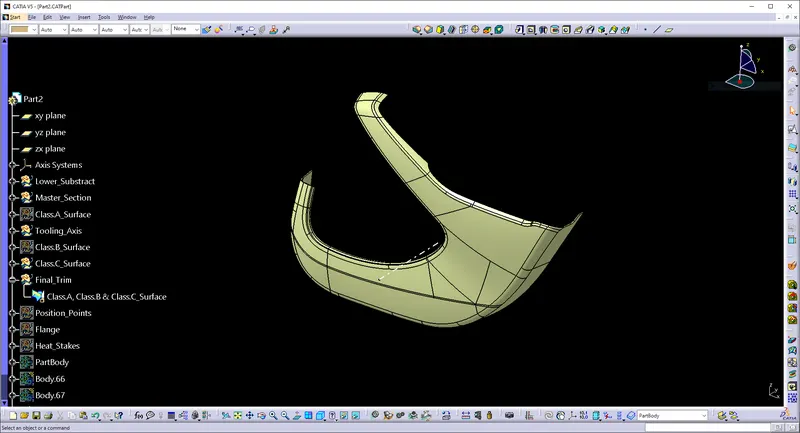
Isometric View:
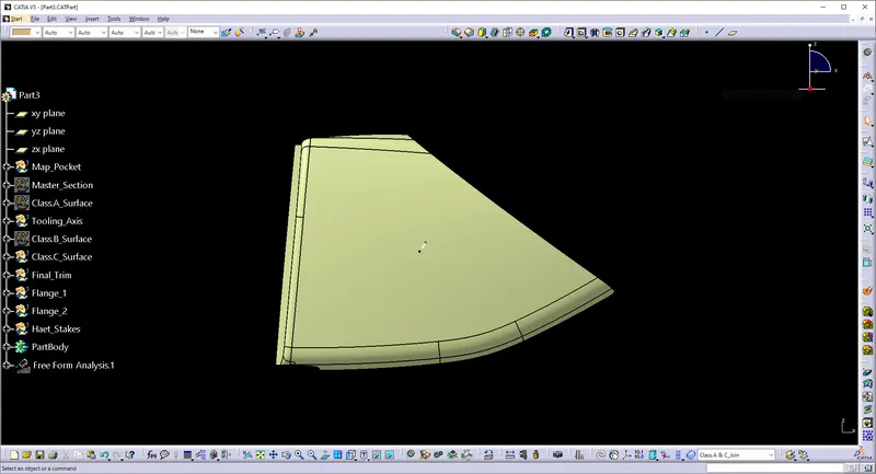
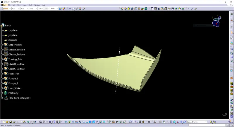
Map_Pocket:
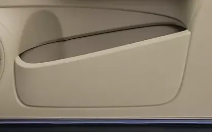
- To keep water bottles from moving around while driving and to store bottles of all shapes and sizes, a map pocket structure for vehicles is offered.
Class.A_Surface:
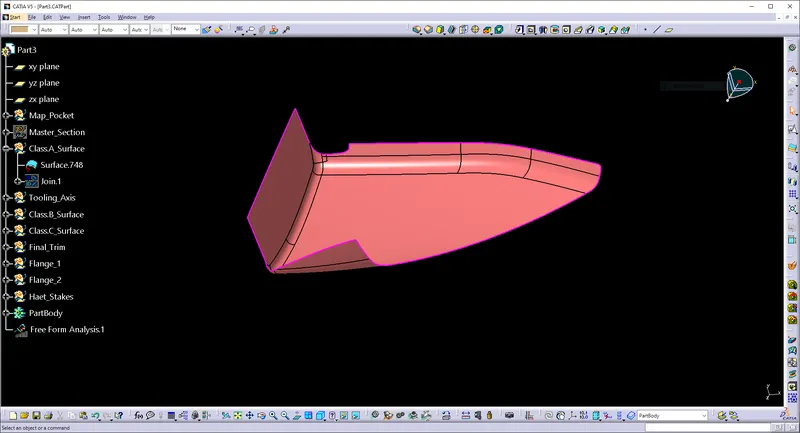
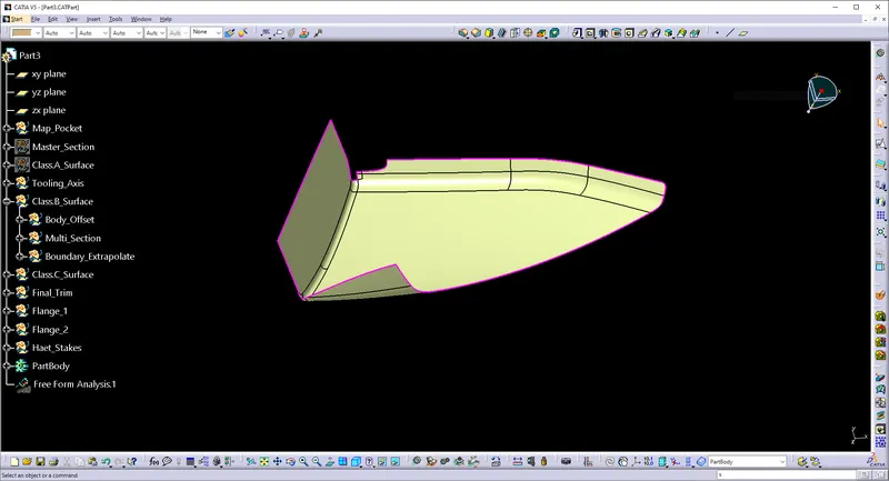
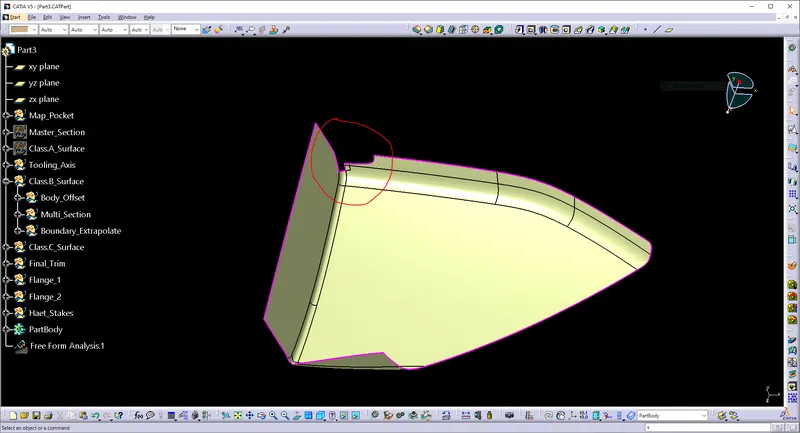
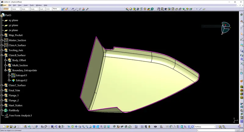
- Error Fixed
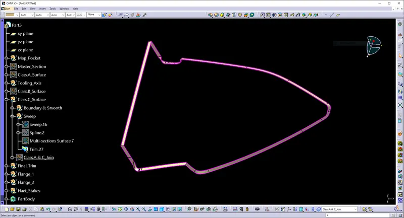
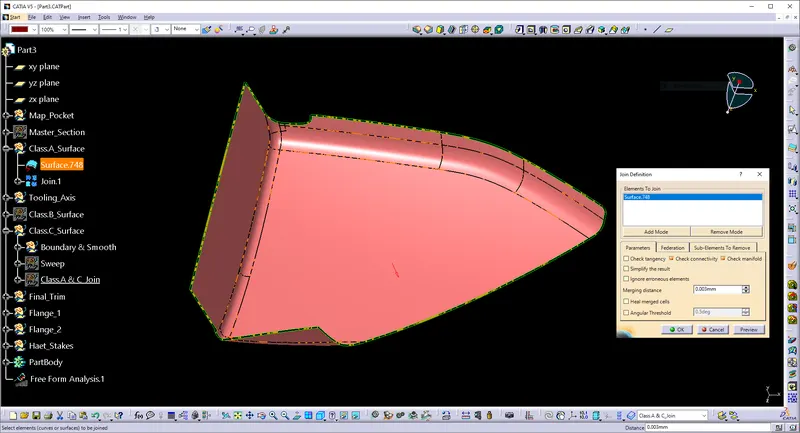
- In Class A surface, must be closed.
- If it is not closed or any invalid features are noticed the part will not going to generate.
- The part is fully constrained, already it's closed we need to proceed. I use the joining method for my Identification.
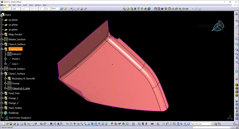
Creating of Tooling Axis:
- Select Insert > Axis System from the menu bar or click Axis System . ...
- Select the point as shown to position the origin of the axis system you wish to create. ...
- If you are not satisfied with the x-axis, for instance, click the X-Axis field and select a line to define a new direction for the x-axis.
Class.A & Class.C_Joining:
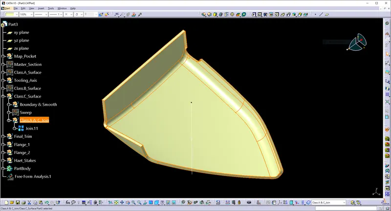
- In a process of joining A & C, it should be a closed surface.
Class.A & Class.B & Class.C_Joining:
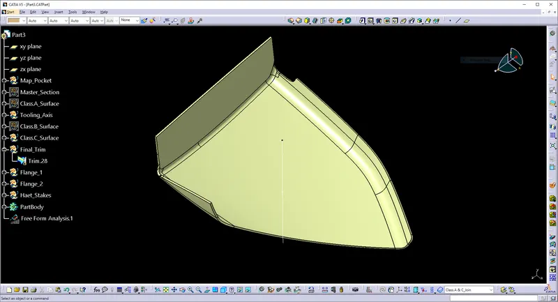
Draft Analysis:
- The draught analysis approach is used to determine whether our CAD-created part model is capable of being manufactured given the draught condition employed.
- Here, the component should be simple to remove from the panel dies (for sheet metal parts) or Mold (in plastic case).
Representation of the color range:
- Green color - Verify whether the draft meets your needs.
- Blue color - Determine the error.
- Red color - Make a distinction between the cavity and the core.
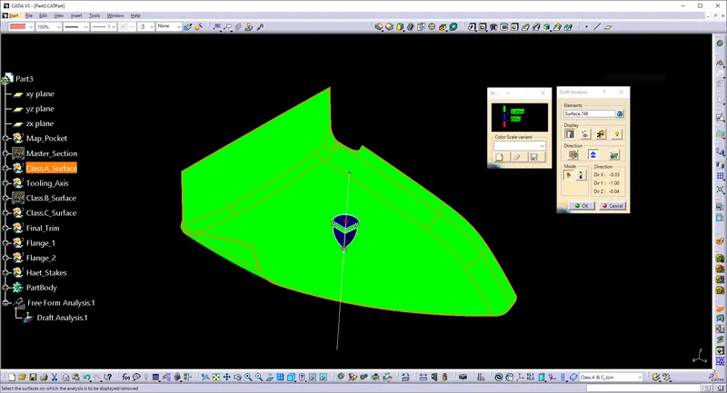
Draft Analysis on Class-A Surface:
- Enter analysis, feature draught analysis, and insert.
- Align the compass and the tooling axis.
- Click the surface to verify that it is within the draught values' permitted range.
- The surface should be green, and the nominal input value for the column should be 3 degrees.
- As a result, the draught analysis on the class-A surface was completed satisfactorily.
Draft Analysis on Final Part:
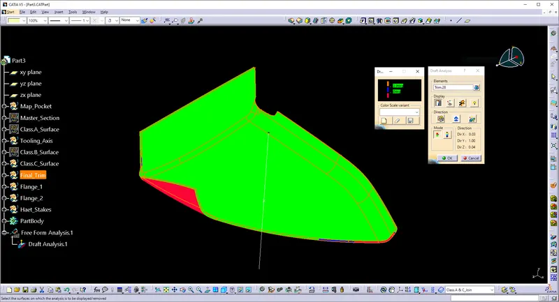
- Using the draught analysis command, you can determine whether the part you drafted will be simple to remove.
- In this kind of analysis, zones on the investigated element are identified by color ranges where the deviation from the draught direction at any given place corresponds to predetermined values.
Orientation of Class A, B, & C, Surfaces:
Front View:
Top View:
Left View:
Isometric View:
Bottle_Holder:
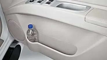
- A bottle holder is an integrated part of the door trim on an automobile's interior.
- It is situated between the lower substrate and the map pocket.
- Bottle storage space and additional room for various uses are provided by this component in the door panel.
Class.A_Surface:
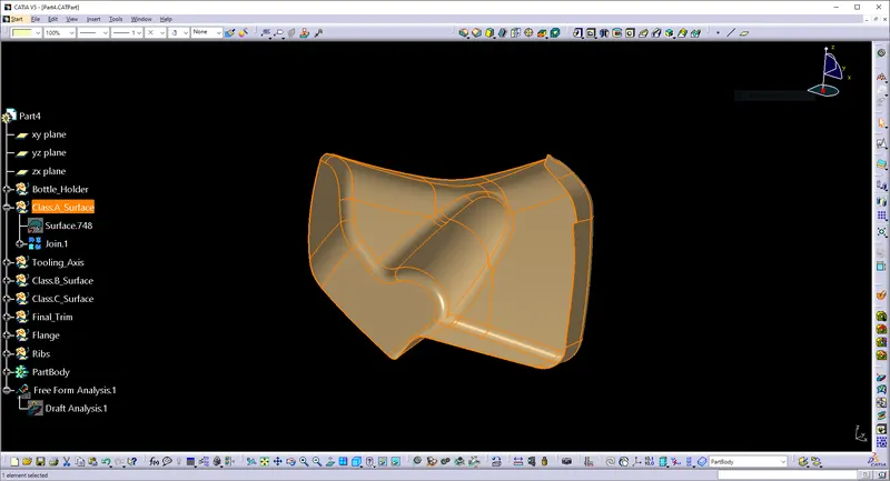
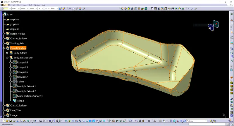
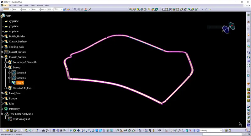
- In Class A surface, must be closed.
- If it is not closed or any invalid features are noticed the part will not going to generate.
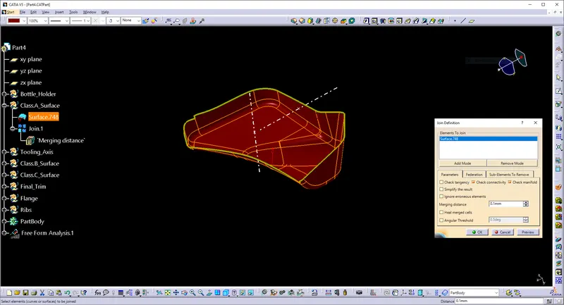
- The part is fully constrained, already it's closed we need to proceed. I use the joining method for my Identification.
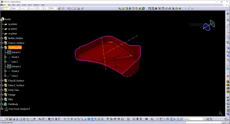
Creating of Tooling Axis:
- Select Insert > Axis System from the menu bar or click Axis System . ...
- Select the point as shown to position the origin of the axis system you wish to create. ...
- If you are not satisfied with the x-axis, for instance, click the X-Axis field and select a line to define a new direction for the x-axis.
- Here we created 2-tooling Axis because of draft analysis didn't clear.
- In thisBottle_Holder design, they create 2 operations to manufacture as slider & Lifter.
Class.A & Class.C_Joining:
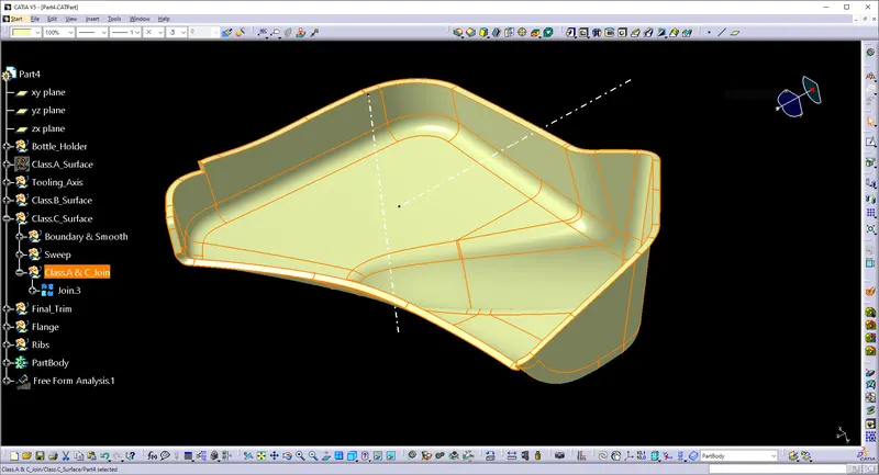
- In a process of joining A & C, it should be a closed surface.
Class.A & Class.B & Class.C_Joining:
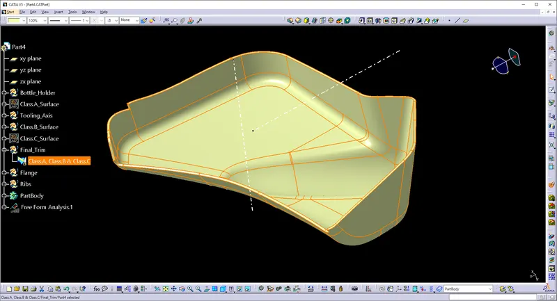
Draft Analysis:
- The draught analysis approach is used to determine whether our CAD-created part model is capable of being manufactured given the draught condition employed.
- Here, the component should be simple to remove from the panel dies (for sheet metal parts) or Mold (in plastic case).
Representation of the color range:
- Green color - Verify whether the draft meets your needs.
- Blue color - Determine the error.
- Red color - Make a distinction between the cavity and the core.
Draft Analysis on Class-A Surface:
- Enter analysis, feature draught analysis, and insert.
- Align the compass and the tooling axis.
- Click the surface to verify that it is within the draught values' permitted range.
- The surface should be green, and the nominal input value for the column should be 3 degrees.
- As a result, the draught analysis on the class-A surface was completed satisfactorily.
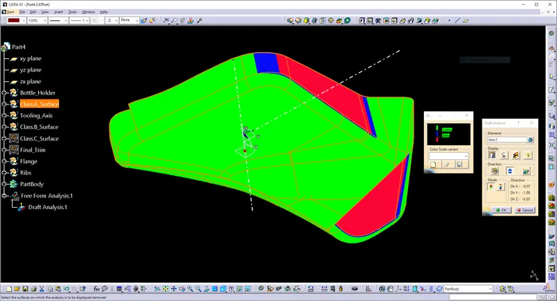
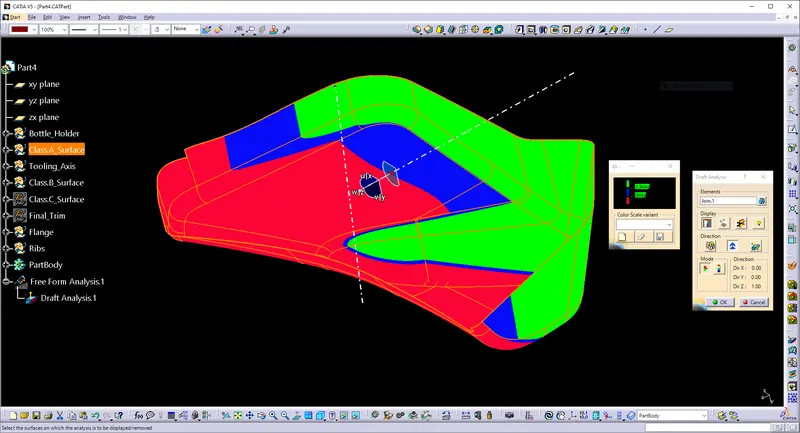
Draft Analysis on Final Part:
- Using the draught analysis command, you can determine whether the part you drafted will be simple to remove.
- In this kind of analysis, zones on the investigated element are identified by color ranges where the deviation from the draught direction at any given place corresponds to predetermined values.
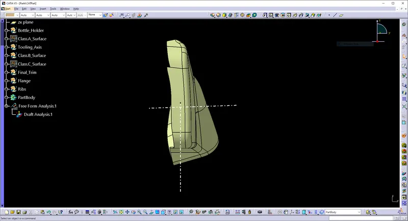
Orientation of Class A, B, & C, Surfaces:
Front View:
Top View:
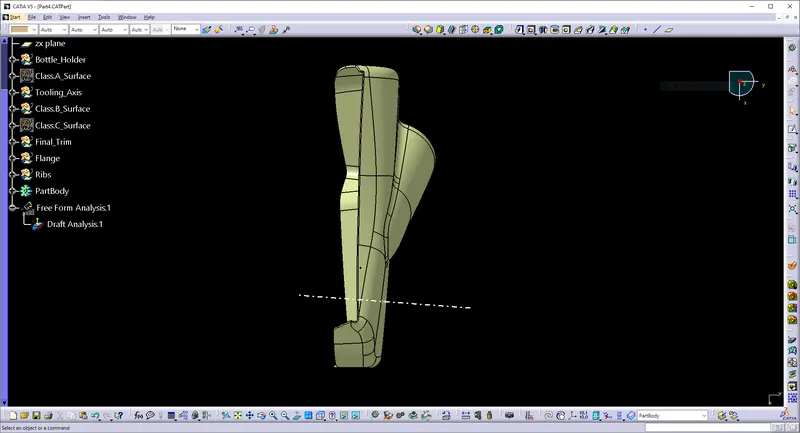
Left View:
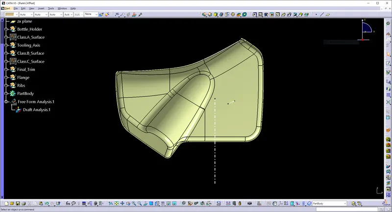
Isometric View:
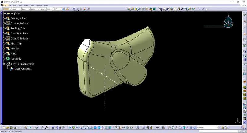
Flanges:
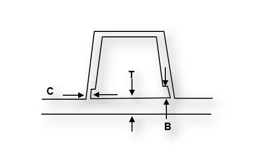
- These flanges will be built on the components for the purpose of fitment with the lower substrate.
- Along the heat stakes, the center hole will be directed.
- In the future, the heat stake's upper portion will melt over it. The supporting side ribs are where the flange should sit. When welding flanges, there is no contact.
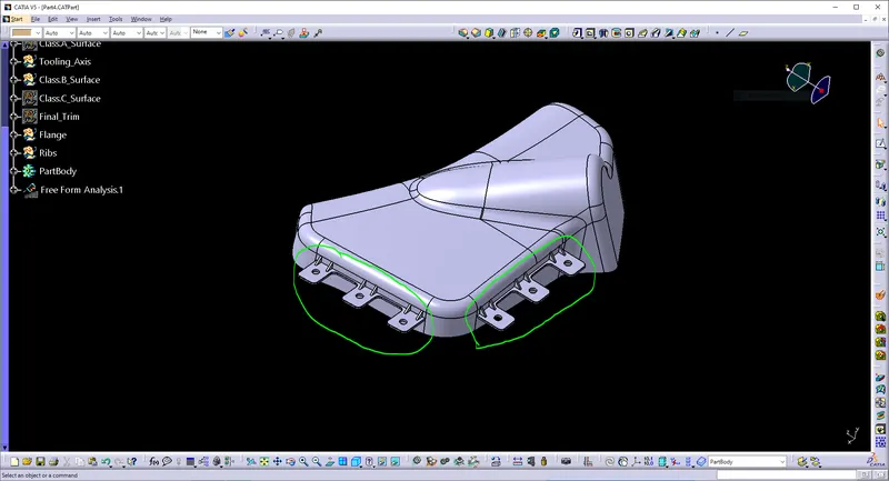
Heat Stakes:
- The technique of putting two different materials together is known as heat staking, also referred to as thermoplastic staking.
- In heat staking, we boost the temperature of plastic components and enable plastic reformation by using local heating and cooling.
- Applications include attaching PCBs to plastic housings and staking plastic bosses for automobile door panel assembly.
- Benefits of this method include the absence of vibration damage, the absence of particles, the ability to stake applications with metalized coatings, and the capacity to stake in locations with restricted access.
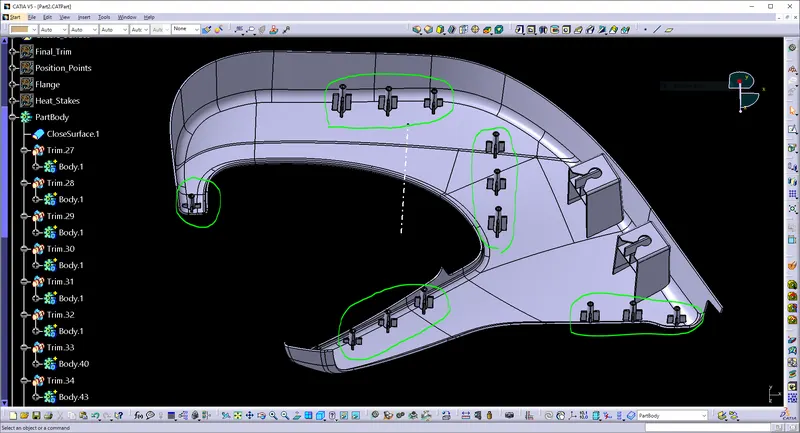
Dog House:
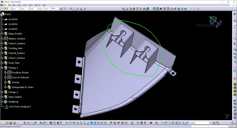
- Plastic design makes use of an engineering feature called a dog house.
- Dog houses serve as a support element to increase their strength, other engineering features like snaps, locators, and screw bosses may be mounted on them.
Draft analysis is performed on dog houses to prevent component breakage during ejection from the mold cavity. - On the B-surface, the dog house and other engineering components are constructed.
Attachment Features and Creation Using Master Section:
Solid Body with Attachment Feature:
Final Model:
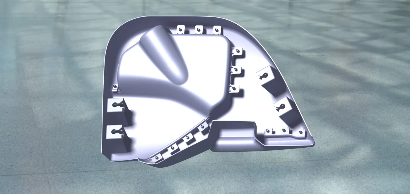
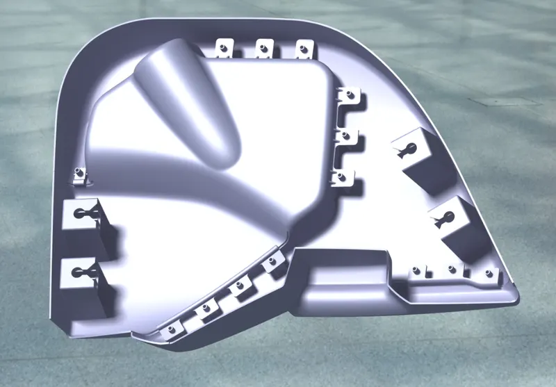
Rendering:
Draft Analysis:
Procedure:
- Change the view mode to customize view parameters and give material as view mode.
- In the draft analysis toolbar, set the draft values and color (3 degrees and above - green, 0 to 3 degrees - blue, less than 0 - red).
- Drag and drop the axis system on the tooling axis and lock it.
- Perform draft analysis.
Conclusion:
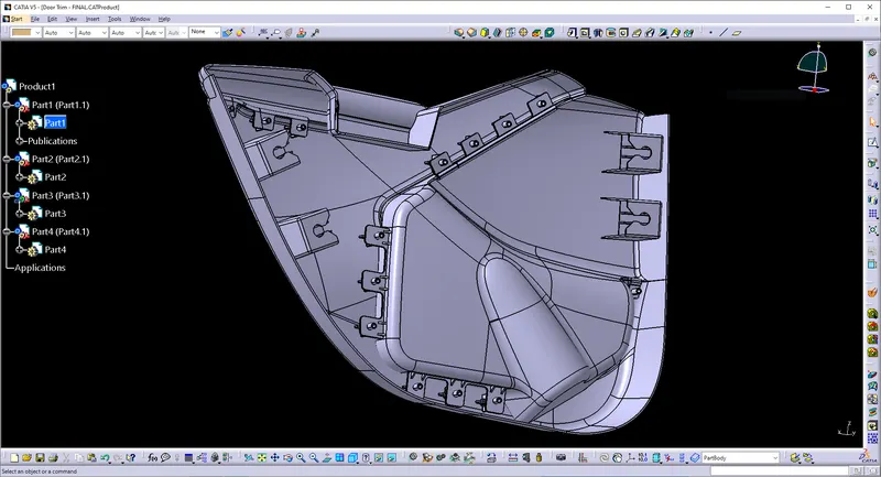
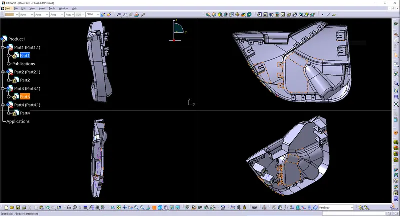
- Using the door trim's Lower CLASS A surface, the created main tooling axis, and the CLASS B and C surfaces were successfully created.
- The examination of the Ribs, Heat stakes, Dog houses, 2-way, and 4-way locators, and the last part in its drafted and fixed on the entryway trim and concluded.