Week 11 - Final project
DEVELOPMENT OF DOOR TRIM PANEL
AIM
To design and development of vehicle interior door trim using given class A surface along with master section. Also create the side attachment features as per design rules.
OBJECTIVE
- To create the thickened part using master section for reference.
- To Create the mounting features are per design rules in the industry and with master sections.
- To creating tooling axis and perform draft analysis.
INTRODUCTION
The door panel is the interference between the interior of the car and the inner workings of the door. Generally, the door panel is divided into two parts of easy designing like arm rest, map pocket, lower substrate, bottle holder, these requires one of the toughest requirements among the interior parts of the car. This should be designed to with stand the load while being less than 2mm in the thickness and also protect the occupants during collisions. Door currently has an inner full width panel consisting of electronic windows. Central locking system and speakers. These panels typically consist of a covered with either textiles or plastics.
A surface:
A surface is the styling surface that is visible to the consumer and gives an aesthetic look for the model designed. Surfaces which are having curvature continuity is also called Class A Surface. Engineering features are not added to this surface. Class A is any of set freedom surface high efficiency and quality. Although strictly it is nothing more than surface have curvature and tangency alignment.
B Surface:
Class B surfaces are the secondary surfaces that you can see sometimes includes all the engineering features such as dog house, locators, ribs, flanges, etc. This
surface is the direct offset of the Class A surface which gives thickness to the component.
C Surface:
This surface is the combination of the Class A and Class B surfaces also they are the backside surfaces that can have tool marks, flash, and other imperfections without hurting appearance, function, etc.
Given input
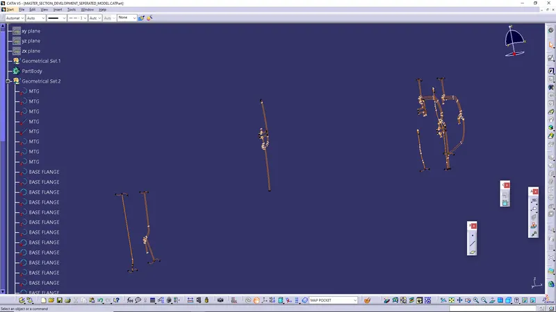
MASTER SECTION
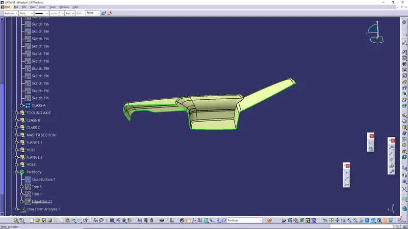
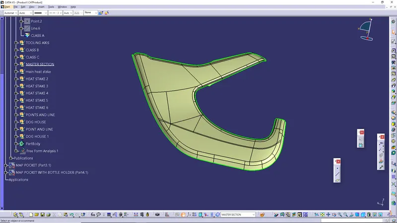
CLASS A OF DOOR ARM REST
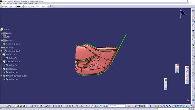
CLASS A OF LOWER SUBSTRACT
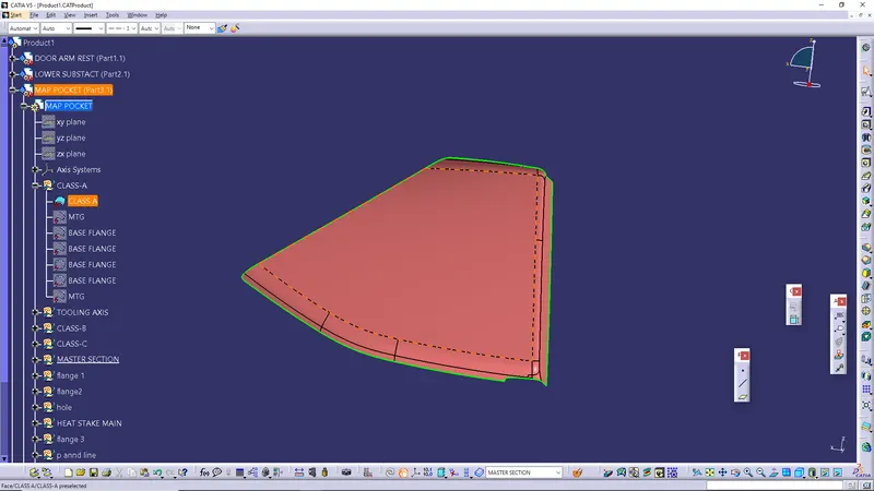
CLASS A OF MAP POCKET
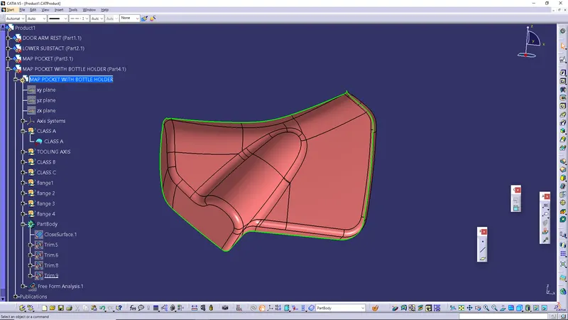
CLASS A OF MAP POCKET WITH BOTTLE HOLDER
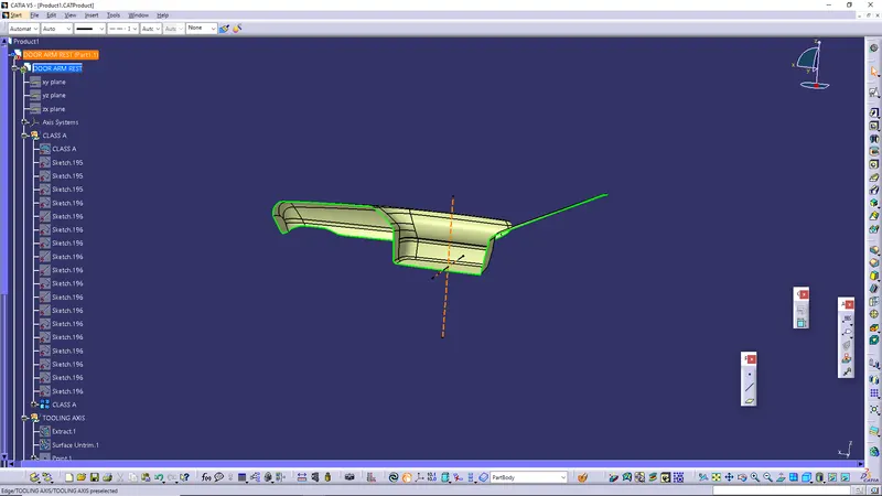
DOOR ARM REST
Tooling axis: - First we extract the lower surface than using point on surface at 0mm create a point. The line has been created using line command. The point direction command is used for create the line (Tooling Axis) along z direction.
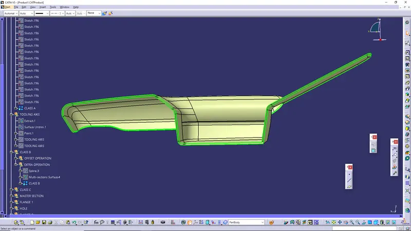
Creation of B surface
Class B surface has been created by offsetting the surface 2.5mm. Surface that are not offsetting were formed by using multi section command and join them.
Creation of C surface
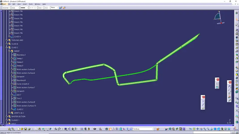
Using the multiple extract commands boundaries of class, A surface were extracted. Class C surface joins class A and Class B surfaces. It is created using the sweep command. Inputs for the sweep were extracted boundary, class a surface angle values and length of the sweep. Due to surface irregularities, it was not possible to make a single sweep. Hence several sweep and multi section were created, and finally they joined together to create a Class C surface.
Creation of solid body
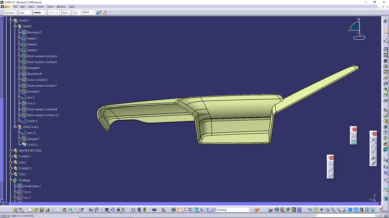
After joining the class, A and class C together, the join surface trimmed with class B surface to create a close surface. Some errors showing that’s why we extrapolate the class B surface for correctly trim the class A and C with class C.
Go to part workbench insert a body and doing close surface operation create the solid body.
DRAFT ANALYSIS-
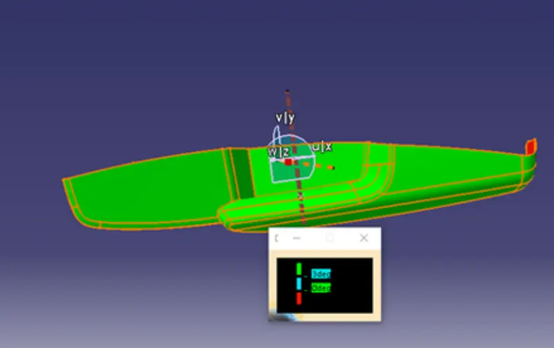
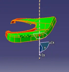
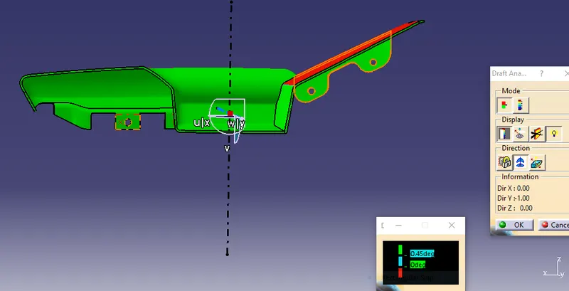
- Final plastic parts are the nominal draft angle is 3 degrees but even 7degree is allowed for the subassemblies like ribs and slots.
- Insert< Analysis< Feature draft analysis
- First the compass is moved to the part which used to define the tooling axis new current draft direction then lock the draft direction using the lock icon.
- The color of the chart indicates the draft if the color is indicated that means the part passes and used for further operation.
- By using the analysis under the running point icon, we can check draft angle at the various surface of the component.
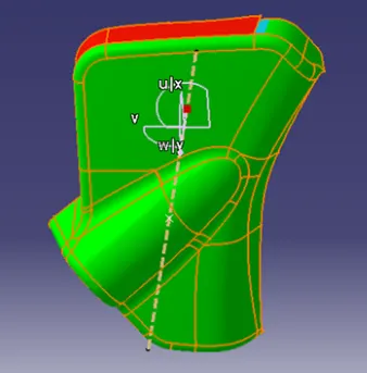
- If the surface satisfied the draft angle, then it shows the green color if not appears in red color.
BOTTLE HOLDER (INNER MAP POCKET)
CREATION OF CLASS A
Extract the inner surface and check the continuity of the surface using join command or boundary command.
CREATION OF TOOLING AXIS
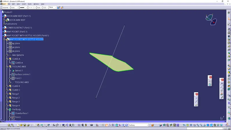
The line has been created using line command. The point direction option is used to create the main tooling axis in the Y direction.
CREATION OF B SURFACE
Class B surface has been created by offsetting of class A surface. Offsetting has been done using offset class A 2.5mm distance .
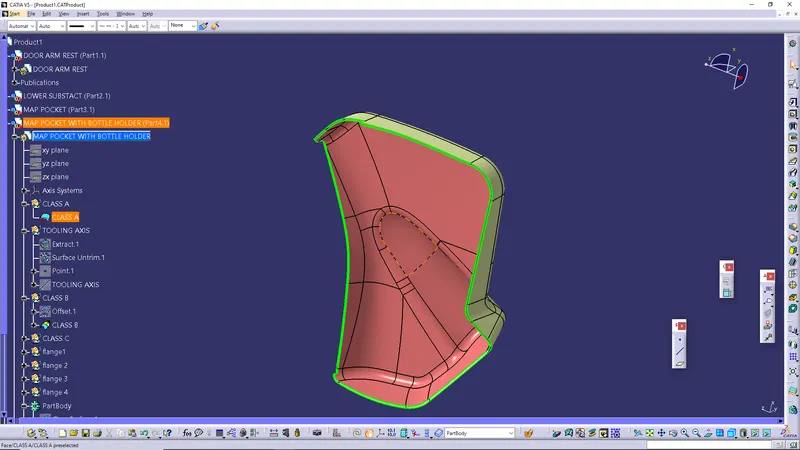
CREATION OF CLASS C SURFACE
Using the multiple extract commands boundaries of class, A surface were extracted. Class C surface joins class A and Class B surfaces. It is created using the sweep command. Inputs for the sweep were extracted boundary, class a surface angle values and length of the sweep. Due to surface irregularities, it was not possible to make a single sweep. Hence several sweep and multi section were created, and finally they joined together to create a Class C surface.
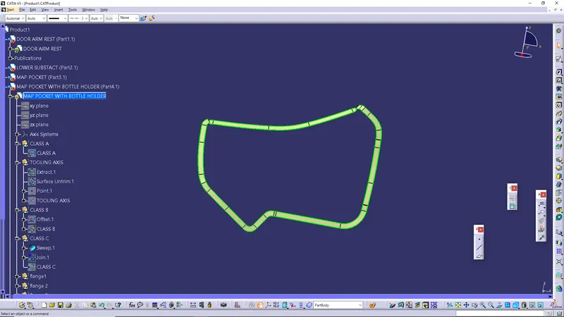
CLOSE BODY
Join the class c with class A. And trimmed with class b surface we get the closed surface.
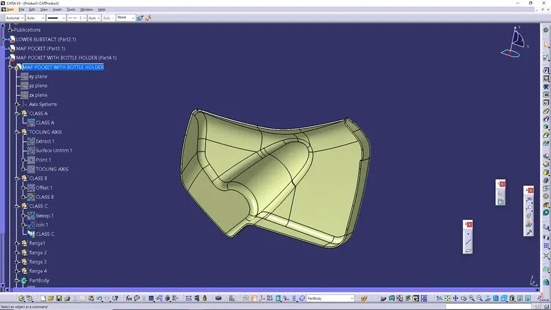
SOLID BODY
After joining the class, A and class C together, the join surface trimmed with class B surface to create a close surface. Some errors showing that’s why we extrapolate the class B surface for correctly trim the class A and C with class C.
Go to part workbench insert a body and doing close surface operation create the solid body.
DRAFT ANALYSIS
CLASS A
LOWER SUBTRACT
CLASS A SURFACE &TOOLING AXIS
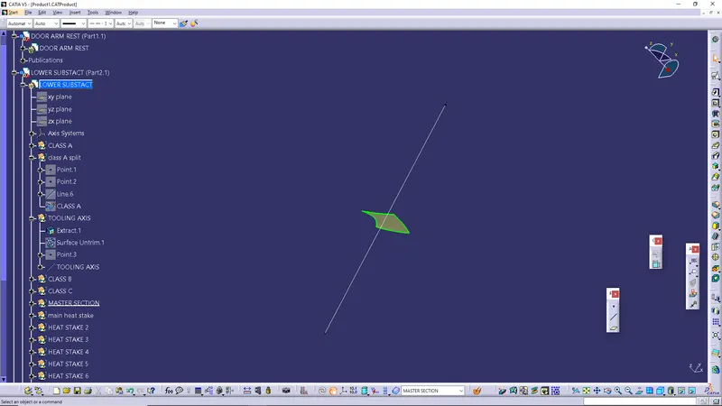
Extract the inner surface and check the continuity of the surface using join command or boundary command.
Create a point on surface 0mm.The line has been created using line command. The point direction option is used to create the main tooling axis in the Y direction.
CREATION OF CLASS B SURFACE
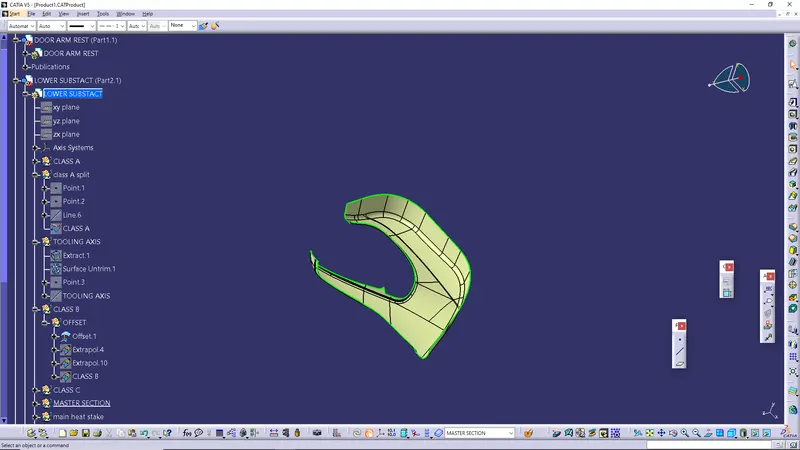
Class B surface has been created by offsetting of class A surface. Offsetting has been done using offset class A 2.5mm distance.
CREATION OF CLASS C SURFACE
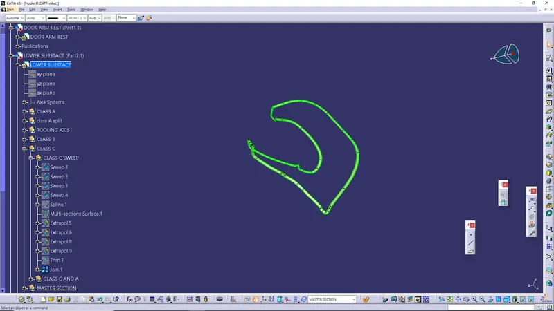
Using the multiple extract commands boundaries of class, A surface were extracted. Class C surface joins class A and Class B surfaces. It is created using the sweep command. Inputs for the sweep were extracted boundary, class a surface angle values and length of the sweep. Due to surface irregularities, it was not possible to make a single sweep. Hence several sweep and multi section were created, and finally they joined together to create a Class C surface.
CREATION OF CLOSE BODY AND SOLID BODY
Join the class c with class A. And trimmed with class b surface we get the closed surface.
After joining the class, A and class C together, the join surface trimmed with class B surface to create a close surface. Some errors showing that’s why we extrapolate the class B surface for correctly trim the class A and C with class C.
Go to part workbench insert a body and doing close surface operation create the solid body.
DRAFT ANALYSIS OF CLASS A
INNER MAP POCKET
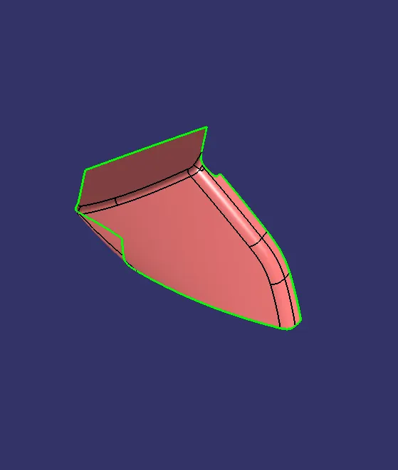
CREATION CLASS A SURFACE
Extract the inner surface from the input .
CREATION OF TOOLING AXIS
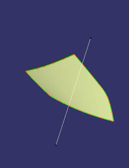
The tooling axis created using line command. The point -direction option used to create line.
CREATION OF CLASS B
Class B surface has been created by offsetting of class A surface. Offsetting has been done using offset class A 2.5mm distance.
CREATION OF CLASS C
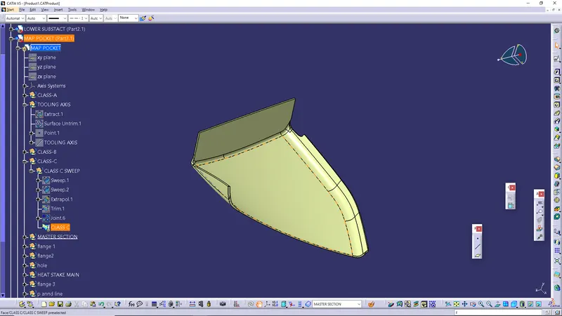
Using the multiple extract commands boundaries of class, A surface were extracted. Class C surface joins class A and Class B surfaces. It is created using the sweep command. Inputs for the sweep were extracted boundary, class a surface angle values and length of the sweep. Due to surface irregularities, it was not possible to make a single sweep. Hence several sweep and multi
section was created, and finally they joined together to create a Class C surface.
CREATION OF CLOSE SURFACE
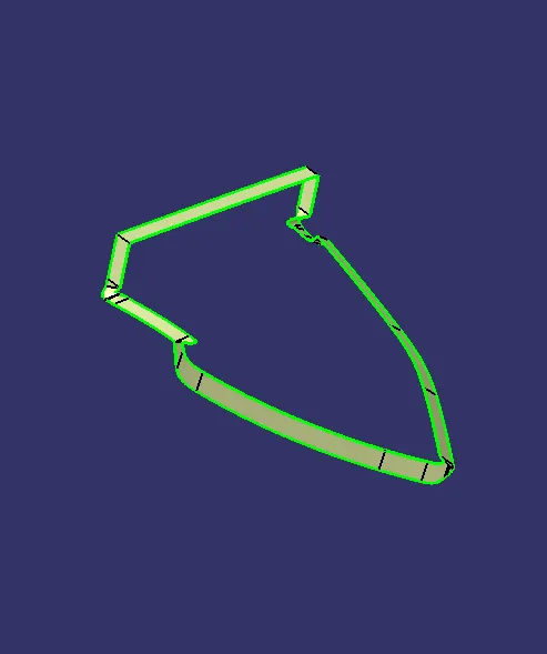
Class A and Class C surface are joined together, trim with class B and create close surface. And the close surface converted into close body.
PUSH PIN
Push pin which helps us locating and arresting component of an assembly and it provides alignment in matting parts and also acts as various guide of mechanism.
CREATION OF ENGINEERING FEATURES
FLANGE-Flange are needed to join different component together, so I have to create flange as design guidelines of master section given as the input basically the measurement and location of the flange.
RIBS- Ribs provide a means to economical stiffness and strength in molded parts without increasing overall wall thickness. They also facilitate:
1) Locating & arresting components of an assembly.
2) Providing alignment in mating parts.
3) Acting as stops or guides for mechanisms.
DESIGN RULES FOR RIBS:
- Draft: 0.5 deg per side (minimum), but this value should not be high enough that it will cause
failure for other considerations. For example, more draft will result in less thickness at the top surface.
- Thickness of ribs: 40% of wall thickness or 0.4*t where t is the wall thickness.
- Height: ≤ 5 times the wall thickness i.e., 5*t.
- Spacing (for more than 1 rib): 3:1- steel height/width ratio (maximum). h/w =3or2(preferred)
where h is the height of the rib and ‘W’ is the space between two ribs.
- Minimum thickness at the tip: 0.75
- Radius: 0.25mm max.
- Ribs on the opposite side of the wall should be offset.
- Ribs should be connected to other structural features where possible.
- Rib root thickness should not be more than 30% of the wall thickness.
DOG HOUSE
Dog house is an engineering feature used in plastic trim design. The primary function of a dog house is to avoid sink marks on the class A surface which may occur due to features such as a thick screw boss or rib on the backside of Class A. So, the best possible solution is to increase the height and decrease the cross-sectional thickness of the ‘legs’ by using a dog house. We can also use them for solving the necessity of large length features such as a screw boss which may require a large length sometimes. We can use a dog house and make a screw boss above it in such situations. We can also use them for making features that are perpendicular to the main tooling direction.
DESIGN RULES FOR DOG HOUSE:
- Minimum height: Less than 6mm causes steel condition.
- 3:1 ratio of steel width to height. But 2:1 is preferred.
- Minimum width: 3:1 ratio of steel width to height. But 2:1 is preferred.
- Draft: minimum 1.5deg.
- Sink saver: height (C) = 40% of nominal thickness. Width (B) = 3.0mm-6.0mm.
- Optimal radius:25mm
HEAT STAKES
Manufacturing operations currently use many different combinations of attachment methods to keep components together. Common fasteners such as bolts, screw, and rivets can be used to form permanent attachments, but there are attachment methods that don’t require secondary hardware. One of those methods is heat staking which does not require additional fasteners.
Heat staking is the process to attach two separate component together secondary component. It’s a permanent attachment method that doesn’t require any additional material such as adhesive or a solvent to make the permanent bond. The only addition is the heat applied to melt the plastic and tool to shape the plastic to form the mechanical connection.
Heat staking is a great option that is comparable in strength and durability to other operations involving secondary fasteners without extra cost. These connections can also resist corrosion in harsh environments.
REASONS FOR HEAT STAKING-
- Multiple staking shapes for different benefits.
- Excellent durability
- No extra materials are needed
- Increased efficiency
- Easy maintenance.
CREATION OF SOME ENGINEERING FEATURE
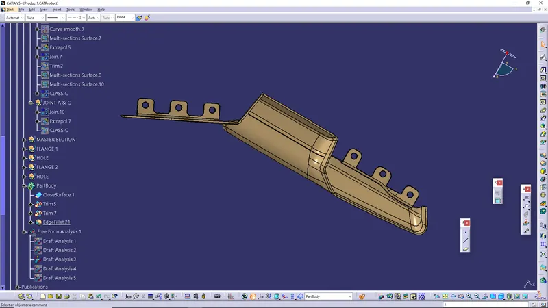
DOOR ARM REST
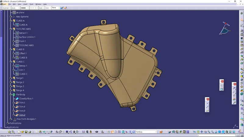
(BOTTLE HOLDER) MAP POCKET
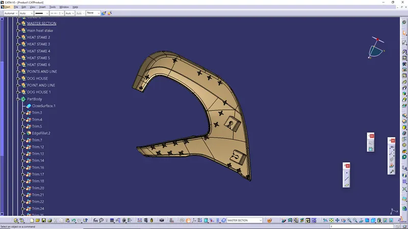
LOWER SUBSTRATE
DRAFT ANALYSIS OF FINAL COMPONENTS
WITH MAIN TOOLING AXIS DRAFT ANALYSIS OF DOOR ARM REST
With side core axis
MAP POCKET DRAFT ANALYSIS
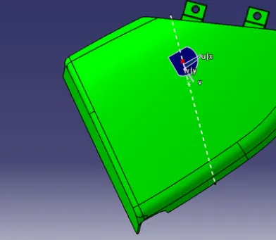
BOTTOLE HOLDER (MAP POCKET) DRAFT ANALYSIS
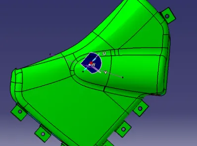
LOWER SUBSTRACT DRAFT ANALYSIS
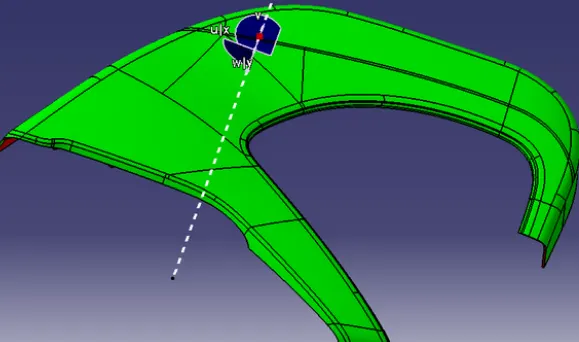
DOG HOUSE WITH SIDE CORE AXIS DRAFT ANALYSIS
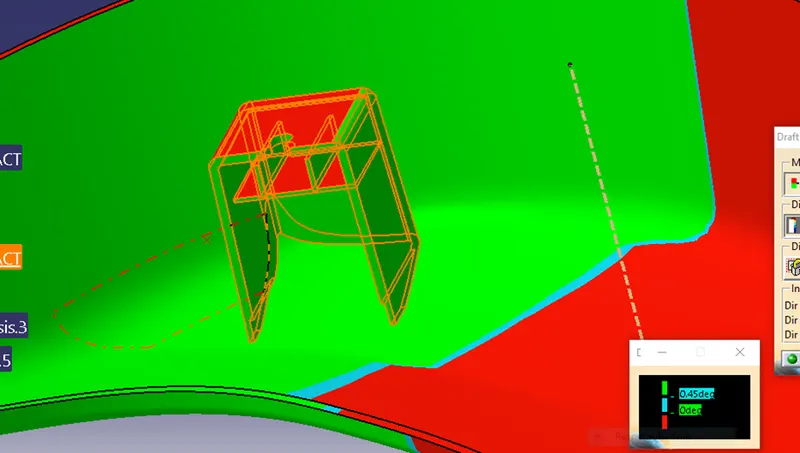
ASSEMBLY
The component is created in separated part files and then inserted into the assembly file. The component is assembled to their working positions by applying assembly constraint to them. Fix the 1st component (LOWER SUBSTRACT) and inserted one by one. Inserted 3 push pin and use constraint to attach them with dog house.
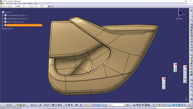
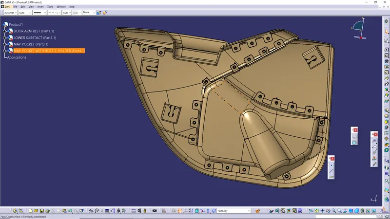
DESIGN VIEW OF ASSEMBLY
ISOMETRIC VIEW
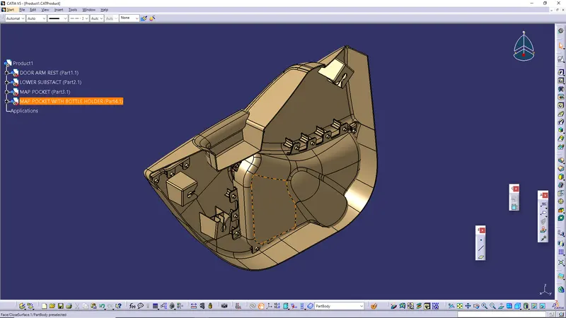
FRONT VIEW
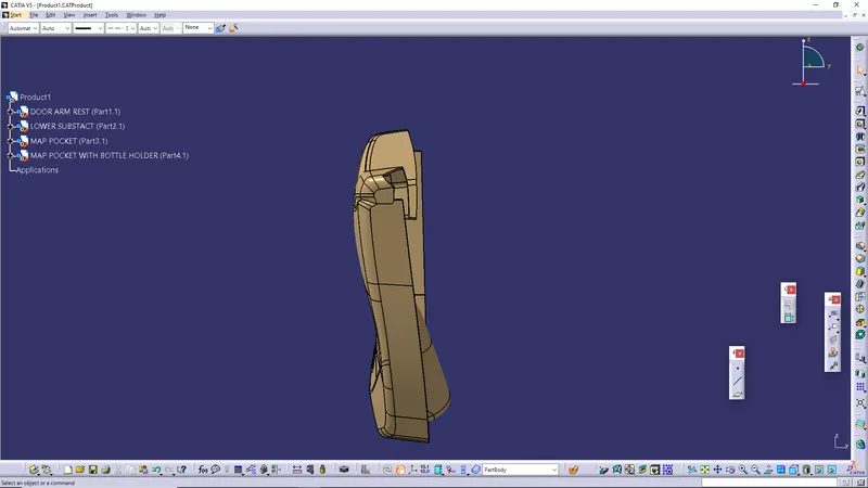
RIGHT SIDE VIEW
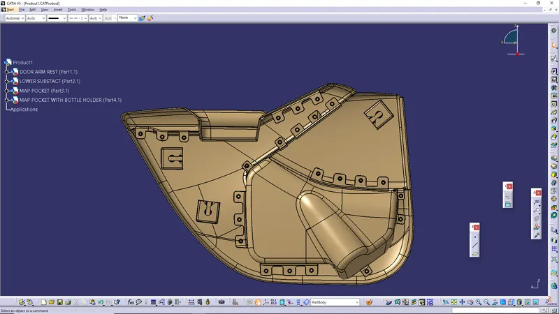
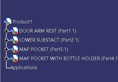
ASSEMBLY TREE
MATERIAL
Polycarbonate (PC) Polypropylene (PP) Polystyrene (PS) Acrylonitrile butadiene styrene (ABS)
CONCLUSION
The door panel successfully designed by following all design rules used in automotive industry. All the attachment feature are properly placed at different location.