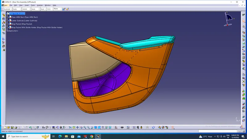
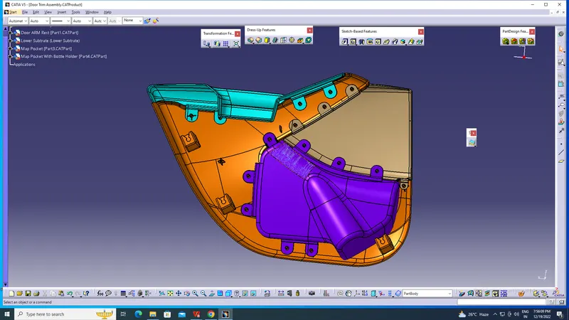
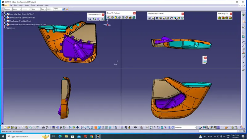
Week 11 - Final project
- WHAT IS TOOL AXIS ?
ANS. WHEN WE CREAT A AXIS FOR ANY PARTICULAR PART OR PRODUCT TO MEASURE DRAFT ANGLE THAT IS TOOL AXIS.
- HOW DID YOU CREAT TOOL AXIS?
ANS. FIRSTLY ON THE REFERENCE OF SURFACE AND TAKE NEW GEOMETRICAL SET,AFTER THAT WE SELECT POINT COMMAND AND SELECT CIRCLE AS A REFERENCE AND POINT PLOTTED AFTER THAT WE GO TO LINE COMMAND AND SELECT POINT AND DIRECTION OPTION CHOOSE POINT AND GIVE Z AXIS DIRECTION AND CREAT LINE. NOW,WE GO TO INSERT SELECT ANALYSIS AND FEATURE DRAFT ANALYSIS OPTION SELECT SURFACE DRAG THE CAMPUS ON LINE AND SWITCH ON THE USES THE CAMPUS TO DEFINE THE NEW CURRENT DRAFT DIRECTION OPTION, AFTER THAT IF YOUR BOTH SIDE OF SURFACE IS GREEN NOW YOUR SURFACE IS READY TO MAKE SURFACE B.
- WHAT IS DRAFT ANALYSIS?WHY DO WE NEED TO PERFORE DRAFT ANALYSIS?
ANS. DRAFT ANALYSIS IS THE WAY TO KNOW DRAFT ANGLE IN SURFACES.BY THE HELP OF DRAFT ANALYSIS WE KNOW THE DRAFT ANGLE IN SURFACE AND ALSO KNOW WHERE IS UNDER CUT.SO, FOR FINDING UNDERCUT WE NEED TO PERFORM DRAFT ANALYSIS.
4.WHAT IS CLASS A SURFACE?
ANS.CLASS A SURFACE IS A VISIBLE SURFACE WHICH SURFACE SEEN BY US IN ANY PRODUCT.IT LOOKS STYLER AND ATTRACTIVE.AND A BEST FINISHING YOU SEEN IN CLASS A SURFACE.
- DRAFT ANALYSIS OF CLASS A SURCAE?
ANS. FIRSTLY ON THE REFERENCE OF SURFACE AND TAKE NEW GEOMETRICAL SET,AFTER THAT WE EXTRACT A FLAT SURFACE AND PLOT A POINT ON SURFACE BY USING POINT ON SURFACE OPTION AFTER THAT MAKE A LINE ON POINT BY USING NORMAL TO SURACE OPTION. NOW,WE GO TO INSERT SELECT ANALYSIS AND FEATURE DRAFT ANALYSIS OPTION SELECT SURFACE DRAG THE CAMPUS ON LINE AND SWITCH ON THE USES THE CAMPUS TO DEFINE THE NEW CURRENT DRAFT DIRECTION OPTION, AFTER THAT IF YOUR BOTH SIDE OF SURFACE IS GREEN NOW YOUR SURFACE IS READY TO MAKE SURFACE B.
6.WHAT IS CLASS B SURFACE?
ANS. CLASS B SURFACE IS A HIDDEN BACK INSIDE PART WHERE MANY SUPPORTS AND MARKS ARE VISIBLE BUT THIS A HIDDEN FACE SO THAT IS NOT A ISSUE. CLASS B SURFACE IS ALSO A THICNESS OF THE PART.
7.CLASS B CREATION?
ANS. FIRSTLY EXTRACT ALL THE FLAT SURFACE AND UNTRIM ALL THIS AFTER THAT WE EXPTRAPOLATE ALL THE SURFACES AND TRIM AS WE NEED AFTER THAT WE MEASURE ALL THE RADIUS FROM SURFACE A AND GIVE THE RADIUS IN SURFACE B .NOW YOUR SURFACE B IS READY.
8.WHAT IS CLASS C SURFACE?
ANS. THE COMBINATION OF CLASS A SURFACE AND CLASS B SURFACE IS CLASS C SURFACE. NOW WE CAN SAY THAT FINAL SURFACE IS A CLASS C SURFACE IN WHICH CLASS A SURFACE ,CLASS B SURFACE AND THICKNESS IS ALSO PRESENT.
- CLASS C CREATION?
ANS. SELECT ALL THE BOUNDARY AFTER THAT SELECT SMOOTH CURVE TO SMOOTH THE BOUNDARIES NOW WE SELECT SWEEP COMMAND AND SELECT GUIDE CURE AND ANGLE GIVE DRAFT ANGLE AND SELECT WHERE IS ANGLE EXTERIOR OR INTERIOR. NOW OFFSET B SURFACE HOW MANY YOU WANT WITHOUT PROVIDING RADIUS AND TRIM WITH THW BOUNDARIES THAT YOU MAKE AND NOW WE FOUND CLOSE SURFACE.
- FINAL SOLID BODY DRAFT ANALYSIS?
ANS.GO TO PART DESIGN CHOOSE SOLID OPTION SELECT PART NOW YOUR PART IS BECOME SOLIDE AFTER THAT UNHINE THE LINE WHICH U MAKE IN DRAFT ANALYSIS IN CLASS A SURFACE AND WE GO TO INSERT SELECT ANALYSIS AND DRAFT ANALYSIS OPTION SELECT PART DRAG THE CAMPUS ON LINE AND SWITCH ON THE USES THE CAMPUS TO DEFINE THE NEW CURRENT DRAFT DIRECTION OPTION, AFTER THAT IF YOUR BOTH SIDE OF SURFACE IS GREEN, THE DRAFT ANALYSIS IS DONE SUCCESSFULLY.
- JUSTIFICATION OF MANUFACTURING?
ANS. DRAFT ANGLE IN PART DESING MUST BE 3 DEGREE SO THAT WE EASILY EJECT THE PART WITH FRICTION BETWEEN PART AND CORE OR CAVITY.DRAFT ANGLE IS MOST IMPORTANT IN ANY PRODUCT DESIGN.
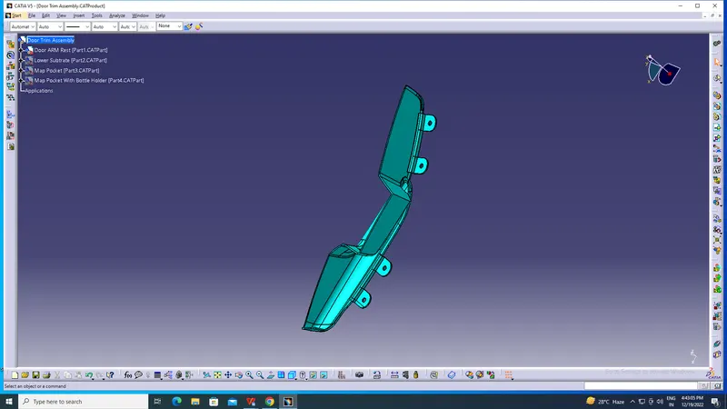
1. DOOR ARM REST-
Arm Rest as the name says it is the part where the driver or the Passenger can rest their hand on. It may come with a soft touch surface such as leather, cloth or any soft material as a wrap around.It may also house various electricals such as the Power Window switches, Mirror adjustment switches etc.It may come with a small storage for coins or sunglasses.
2. LOWER SUBSTRATE-
Lower Substrate is the encapsulating aesthetic Part used in the door panel.It may house various features such as Wirings, Speakers and other sheet metal components behind it.
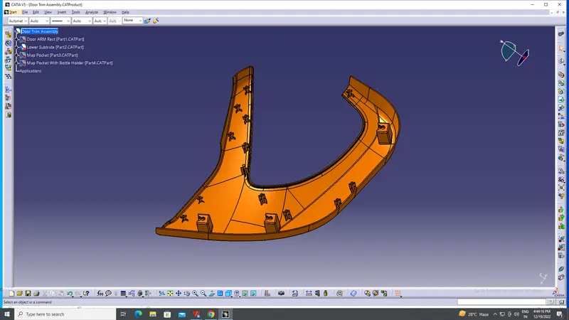
3.MAP POCKET-
Map Pockets are genrally used as storage space on the door.In this case The Map Pocket is divided into 2 sections the upper and LowerThe Upper Section acts as an enclosure from the inner parts and for aesthetics only
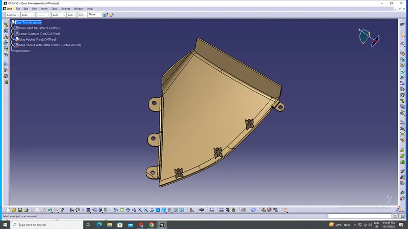
4. MAP POCKET WITH BOTTLE HOLDER-
Map Pockets are genrally used as storage space such as a bottle Holder, Umbrella Holder etc. on the door.The Lower Section of Map Pocket development is shown in further steps.
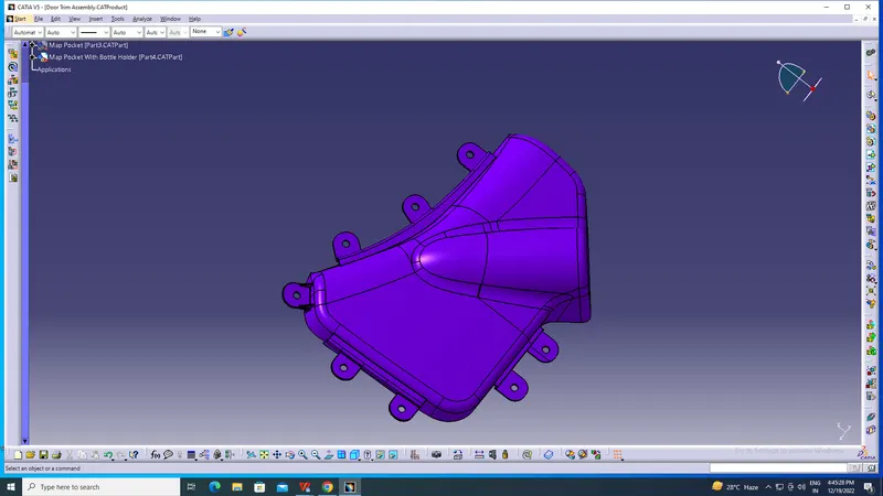
Creating B Side Features--
* HEAT STAKES AND RIBS--
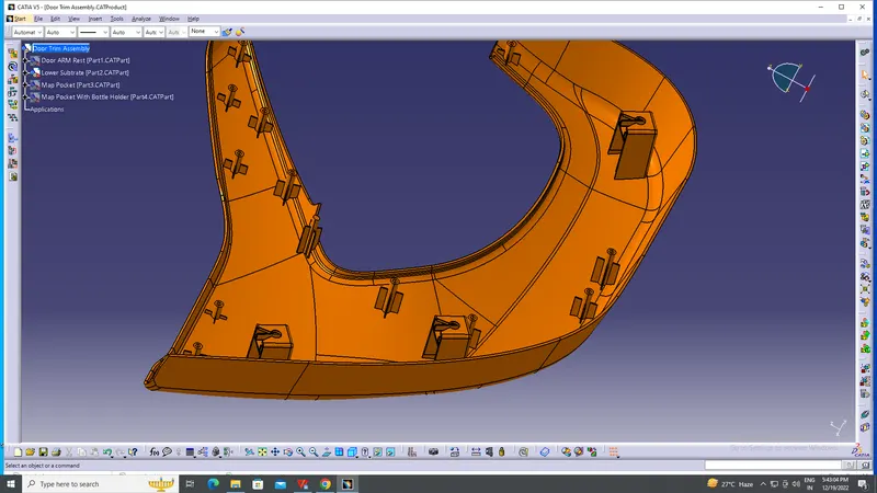
A circle of diameter 4.5mm was made and thickened outside 3mm to get a 7.5mm dia. circle outside. Ribs were added on both sides for strength to the heat stake. 40mm ribs were provided.Multiple heat stakes were made using translate function on various areas of the doghouse. These heat stakes support the bottle holder, map pocket and door armrest.
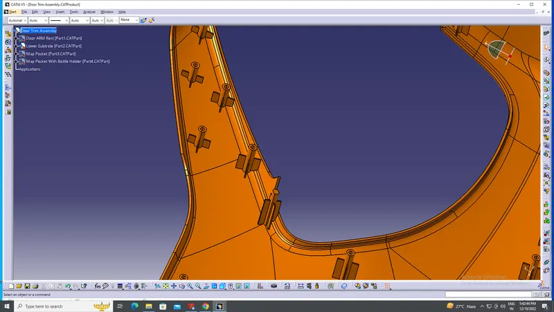
* DRAFT ON HEAT STACKS AND RIBS--
A draft of 0.5 was given to the heat stakes and their ribs. Note that inside draft for the stake will be in the opposite direction to the outside.
Finally, the heat stakes were union trimmed with the lower substrate.
*DOG HOUSES---
3 doghouses were added on the lower side of the lower substract. we make axis system and make a rectangle 30x30mm we pad this 60mm now we gives draft on 1.5mm bt tool axis and shell from the inner side.after this we copy a first skecth and offset 1.5mm for making coring portion after that we draft on 0.5 coring section by lifter axis. after that we made ribs on dogb house along the front face a thick ness of rib is 1.5mm and give draft 0.5 on rib by lifter axis.after by the help of user pattern i placed 3 dog house in different point at last we perform union trim and add dog houses in lower substract.
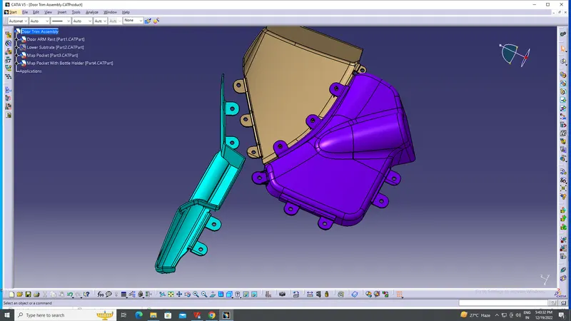
* FLANGES FOR MAP POCKET,MAP POCKECT WITH BOTTLE HOLDER AND ARM REST--
FOR MAKING FLANGES FIRST WE CREAT A LINE AND AXIS SYSTEM AFTER THAT WE SKETCH AND EXTRACT THE UPPER SIDE OUTER LINE AND SWEEP SKETCH ALONG THE EXTRACT LINE AFTER THAT MAKE A SWEEP STRAIGHT AFTER THAT TAKE A TOP PLANE AND SKETCH FLANGS AND EXTRUDE THIS SKETCH AND SPLIT THEM AFTER THAT GIVE THICKNESS, RADIUS AND SUPPORT. AT LAST PERFORM UNION TRIM TO JOIN FLANGES IN THE COMPONENT. AND MAKES A HOLES IN FALNGES FOR HEAT STACKES.PLOT A POINT AND MAKE 3D CIRCLE AND POCKET THEM.
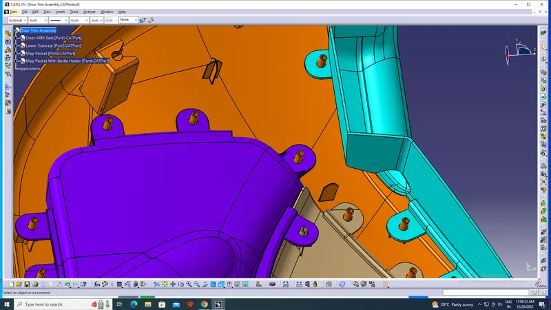
*2 WAY AND 4 WAY LOCATERS--
A 2-way locating pin restricts motion along 1 axis (or 2 degrees of Freedom), like a round pin in a slot. Likewise, a 4-way pin restricts 4 degrees of freedom along 2 axes. A round locating pin located concentrically in a hole is a common application of a 4-way pin, and helps to further secure the piece.4-way mean you prevent movement at 2 axes (+X, -X, +Y and -Y) on the plane. Generally, you have cylindrical pin on the fixture and circular hole at workpiece part.
DRAFT ANALYSIS OF A SURFACE
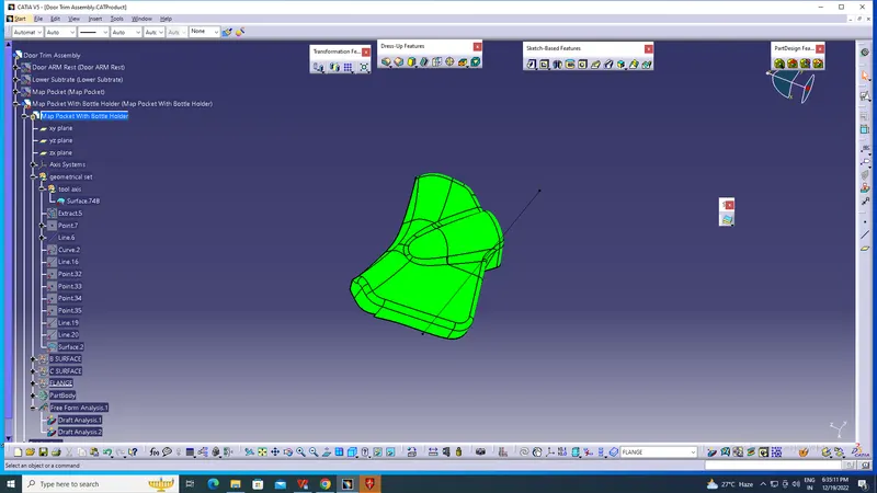
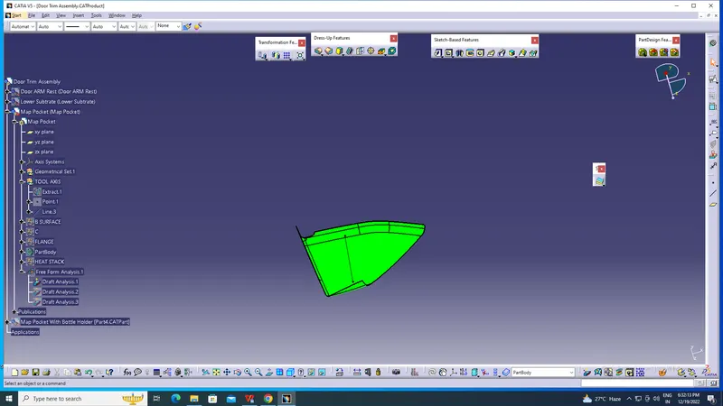
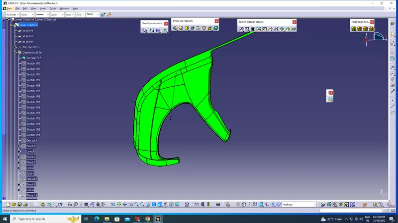
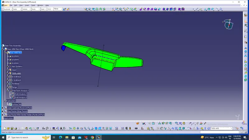
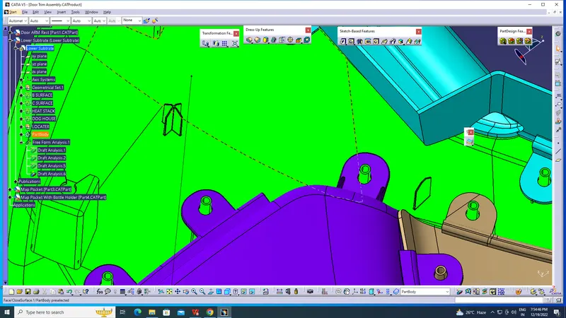
DRAFT ANALYSIS OF B SURFACE FEATURES--
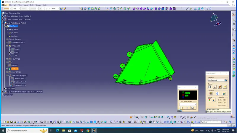
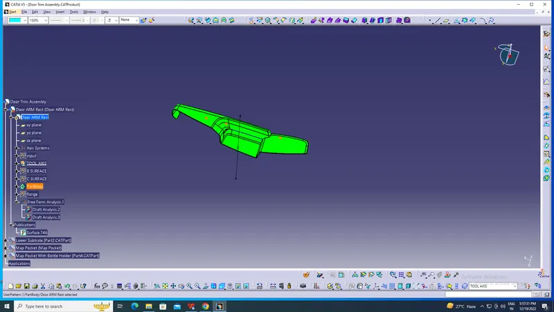
HEAT STACKS DRAFT ANALYSIS
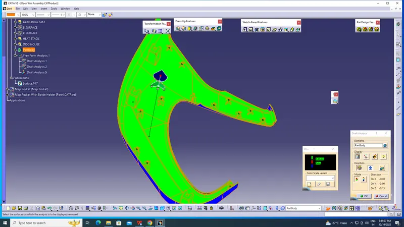
FLANGE DRAFT ANALYSIS
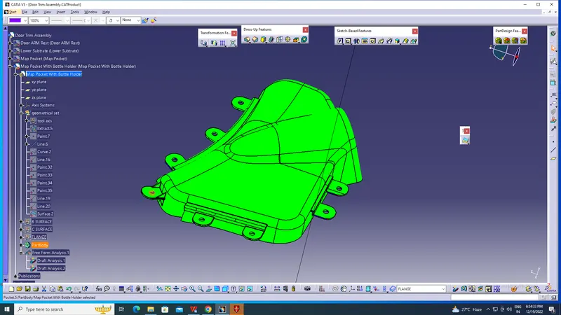
DOG HOUSE DRAFT ANALYSIS
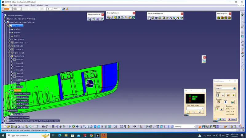
LOCATORS DRAFT ANALYSIS
FINAL DOOR PROJECT--