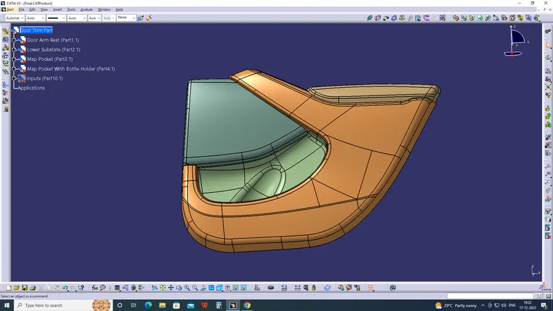
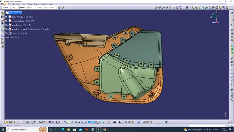
Week 11 - Final project
Objective
With the given input of class A surfaces and master sections, the plastic door trim parts are to be developed following industry standard design guideline using Catia V5 software.
Introduction
Door panels serve as an interface between the interior of the car and the inner workings of the door, and between vehicle occupants and the door. They are expected to meet a variety of design specifications regarding safety, aesthetics, and functionality. In addition, they are expected to continue the material theme of the dashboard and pillars while concealing intricate electrical and mechanical components for operating locks, windows, and other features. The door panel has evolved from a simple two-part system of latch and simple winding mechanism to a more sophisticated enclosure. Doors currently have an inner full-width panel consisting of electronic windows, central locking system, and speakers. These panels typically consist of a foamed core covered with either textiles or plastics.
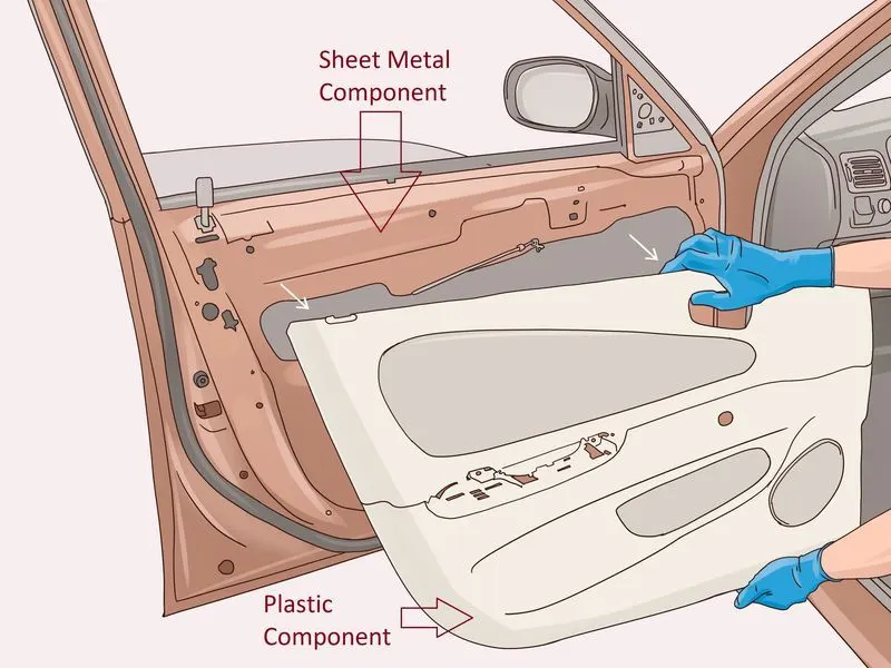
DOOR TRIM PANEL CONSISTS OF FOLLOWING COMPONENTS:
1.DOOR ARM REST
2. MAP POCKET
3.LOWER SUBSTRATE
4.FLANGES
5.HEAT STAKES AND DOG HOUSE
Terms and definitions
Class A surface
This is the styling surface which provides the aesthetic features of a component. A designer starts the component design from a class A surface.
Class B surface
Class B surface is obtained by offsetting the class A surface by the component thickness value. This B surface contains all the engineering features of the component.
Class C surface
Class C surface is created along the tooling direction of the component and connects the class A and class B surfaces.
Draft Angle
Sheet metal and plastic parts that are made by forming, casting, pressing or even molding, require a draft angle at their side walls. Draft angles are the degree of taper that is incorporated into the side wall and cores of the die cast tool to aid in the removal of a part. Primarily, they function to reduce the friction between the part and the tool as it is ejected. Without draft angles, parts can be stripped, dented, or get stuck in the tool.
Draft angles are measured from the Tooling axis of the part. For mould designs where one metal mould component make direct contact with another, a minimum of 3° draft is required to ensure that the mould can separate properly.
Draft Analysis
Draft analysis measures the draft angle on multiple surfaces of a part along the tooling axis to check if the surfaces have the minimum required draft angle for it to be moulded properly.
Tooling Axis
Tooling axis is the direction in which the 2 halves of a mould (core and cavity) opens or closes, or the direction in which the part is released from the mould.
Parting Line
A ‘parting line’ is the line of separation on the plastic part where the two halves of the plastic injection mold meet. The line actually indicates the parting ‘plane’ that passes through the part. Within more basic plastic part design plans this plane can be a simple, flat surface, but it is often a complex form that traces the perimeter of the part around the various features that make up the part’s outer ‘silhouette’.
Ribs
Ribs are thin wall-like structures that add support and rigidity to injection moulded parts. They are thinner than primary walls and are used to support these walls, as well as bosses, by running perpendicular to these structures. Ribs are often used to replace thick wall sections to avoid sink marks, warp, and voids.
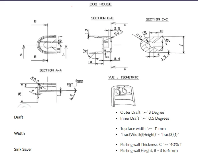
Dog House
Dog house is an engineering feature used in plastic trim design. These are used as supporting feature and other engineering features such as bosses, locators etc are mounted on them to increase their strength. Dog houses require a slider for moulding and are subjected to draft analysis along the slider axis to prevent breakage during ejection from mould cavity.
Heat Staking using heat stakes
Heat staking technology is quite simple in concept. Whenever two or more components need to be attached to one another, and at least one is made of a thermoplastic, a combination of heat and pressure can be used to reform the plastic to the many shapes or profiles to retain or join the parts together.
This creates a solid, hardware-free bond that uses the plastic’s inherent strength to keep the finished assembly together.
Design Process
- For all the parts the class A surface is checked for surface abnormalities, if found ok then the plastic component design is started else the class A surface is sent back to the product design team for correcting it
- Tooling and slide core axis (if required) is created for each of the part and draft analysis of the class A surface is done
- The class B surface is then created by offsetting the class A surface by the component thickness value which is measured from the master sections that are provided
- C surface is then created by extracting the edges of the class A surfaces and sweeping them wrt of the tooling axis or the refernce surfaces
- The A, B and C surfaces are then trimmed and joined to create a closed body
- Flanges and other attachment features are then design on the closed body following the master sections
- Draft analysis is then done on the final body along their respective tooling axis to check the draft provided in the surfaces for proper removal of the part from the moulds
Once all the part design are finalized they are assembled along the Push Pins which are situated right abive the Dog House roof on the Lower Substrate
DOOR TRIM COMPONENYS:
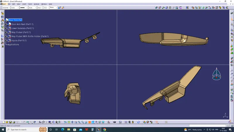
DOOR ARM REST:
LOWER SUBSTATE:
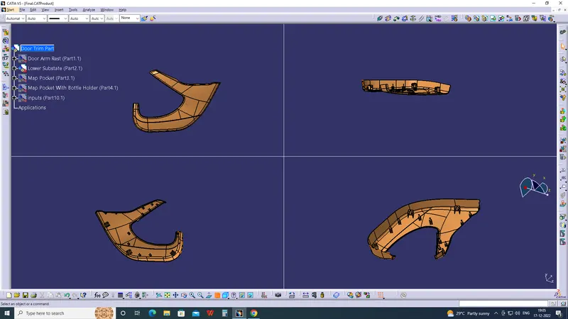
MAP POCKET:
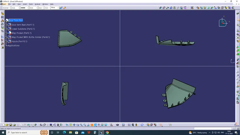
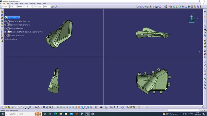
MAP POCKET WITH BOTTLE HOLDER:
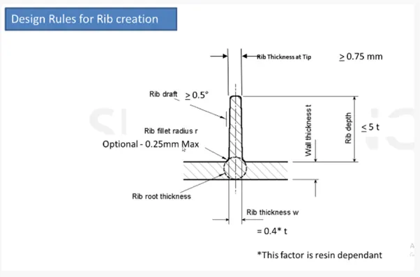
Design rules for Rib creation
- Draft – minimum of 0.5° per side
- Thickness – generally 40% of wall thickness
- Thickness of Tip – minimum of 0.75mm
- Radii – maximum of 0.25
Measurements taken for this design
Draft angle: 0.5degree
Thickness: 1mm
Height: 30mm
Fillet Radius: 0.1mm
Dog House design and guidelines
DRAFT ANALYSIS:
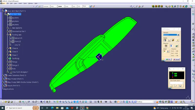
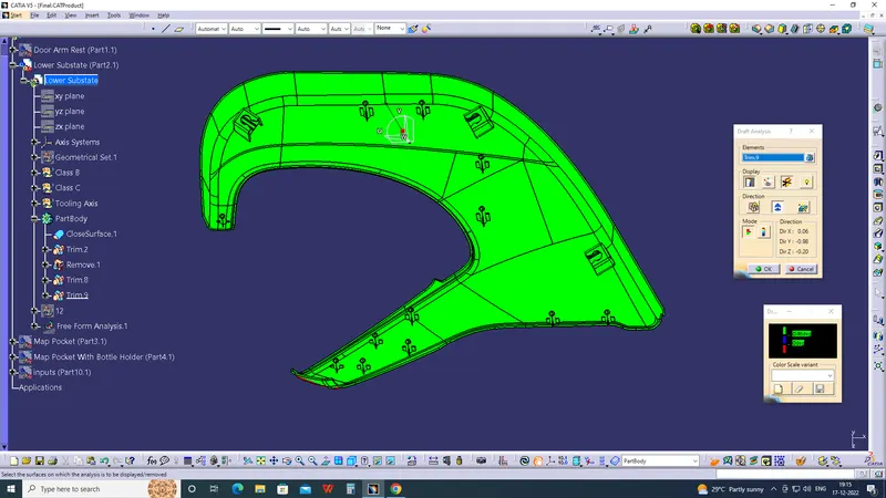
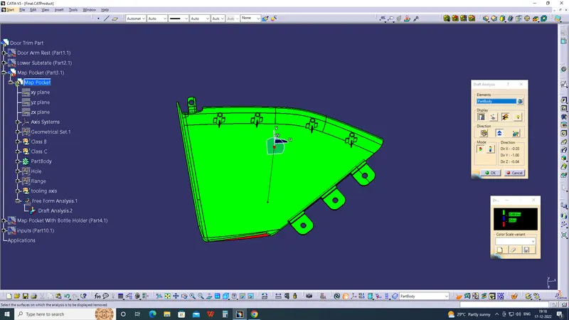
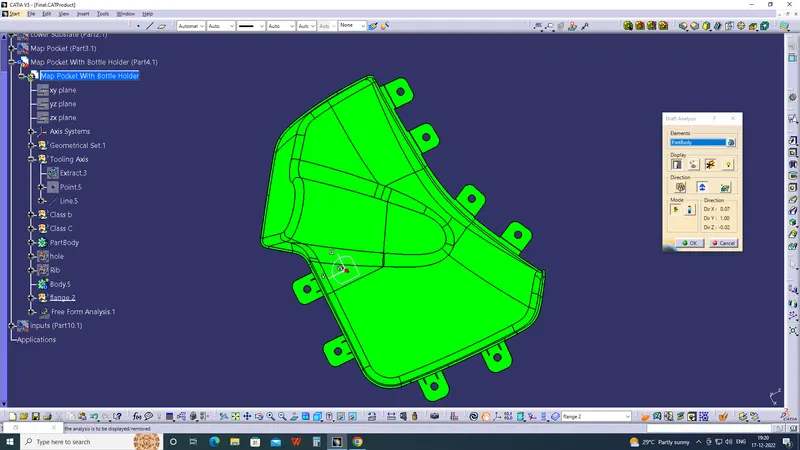
This analysis tells us whether our component will be safely ejected in the tooling axis we have provided. Some components require side core where there are under undercuts, holes or projections on the side walls, so for this we need a different tooling axis and a different analysis is required to check those areas. Draft analysis shows color codes which are defined by the user for different values which also are defined by the user. These colors help us to analysis if the component is clearing the analysis and we are good to go ahead or not. In case the component fails the analysis for class-A then we have to submit the draft analysis report to the higher authority so that the surface of the component can be improved. Failing analysis simply means that the component does not have the required draft value it must have. In case our solid model which we develop, fails the analysis at some parts then we have to correct it ourselves.
We have to make sure that our entire model is green which means it is clearing the analysis. So we have to run analysis for class-A, solid model and other B-side features as every single component, regardless of its size should be ejected safely from the core.
ASSEMBLY: