Week 11 - Final project
MAIN SUBSTRATE
- Main Substrate Class A surface
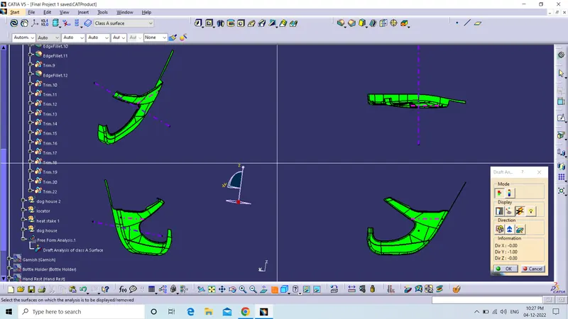
Above the class A surface Draft Analysis which we can see that is green every where which means the tooling Axis that we selected is OK.
Purple Line is the Tooling Axis for the main substrate
- Class B surface
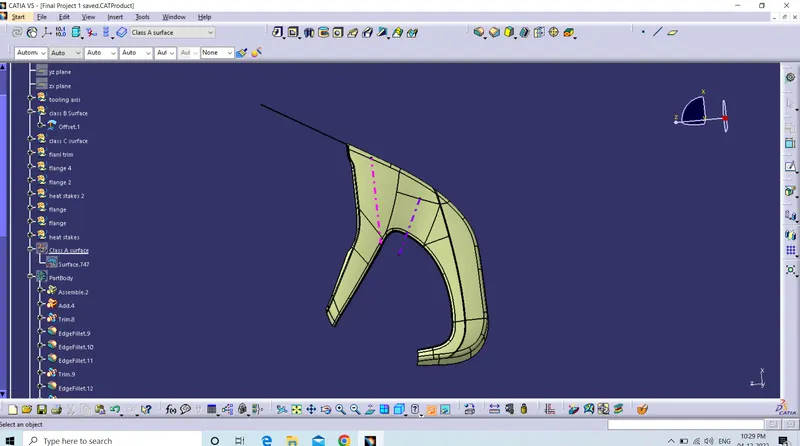
Class B surface is cretaed simply using offset not need to edit anything here.
- Class C surface
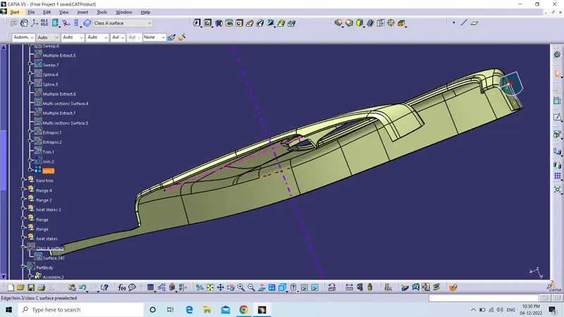
Above is the Class C surface Joined with the Class A surface.
- Final Solid Part
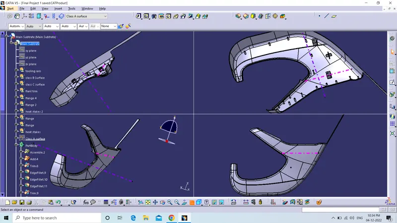
The Solid part along with the attached 4 way locator, Heat Stakes ,Dog House and flange as the attchement features.
- Draft Analysis Report for the Main Substrate Component
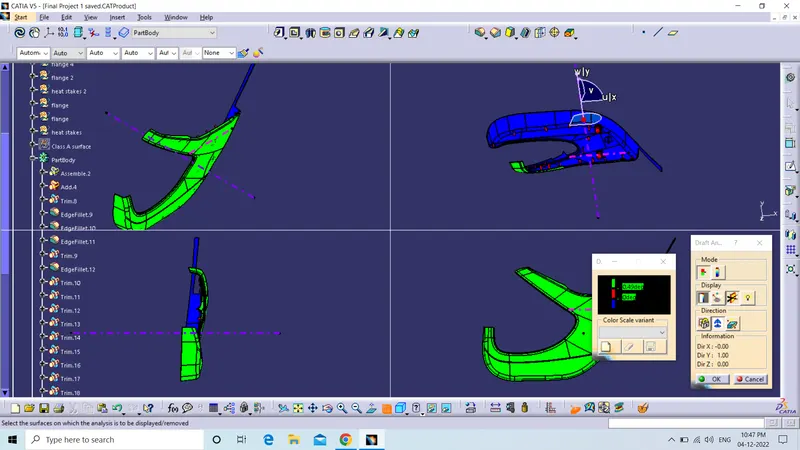
The proper draft is given to the component at every place which is 0.5 degree which is minimum to the heat stakes, dog house and locator pin.
Dog House
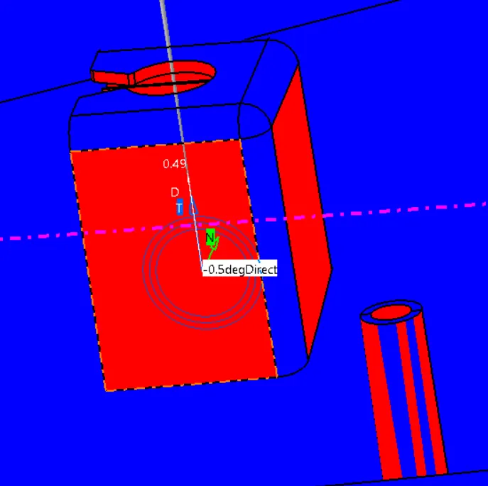
- It is showing in red color but the draft angle is proper which is 0.5 degree as my Catia Version is not ok with the draft analysis. So please open the assembly and perform the draft analysis then Grade the Final Project. So the TSE can see that own his/her owm.
- Draft Analysis Along side core axis is shown below for the dog house
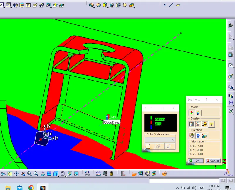
It is showing some red portion but the draft is proper as it is due to the catia version. I'm Also sharing the Pointer photos which shows the draft angle at the red portions.
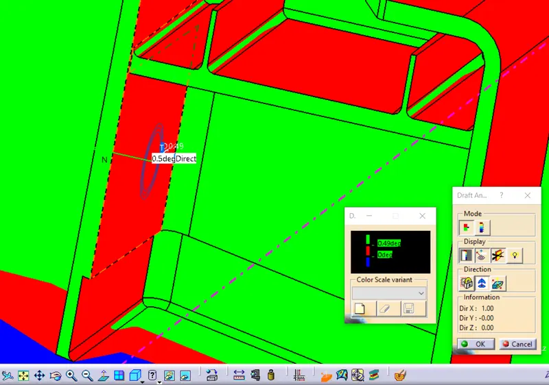
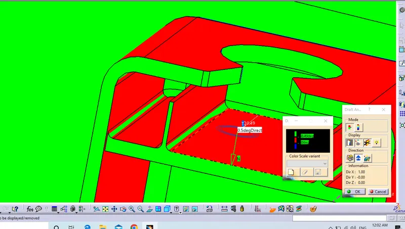
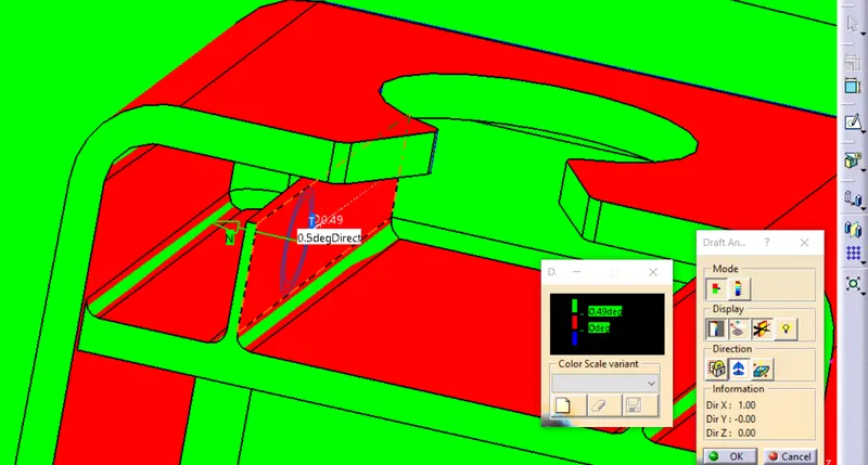
The above 3 pics shows that the draft angle is 0.5 every where which is proper. So the Dog houses are ok. No issue with that.
4- Way Locator
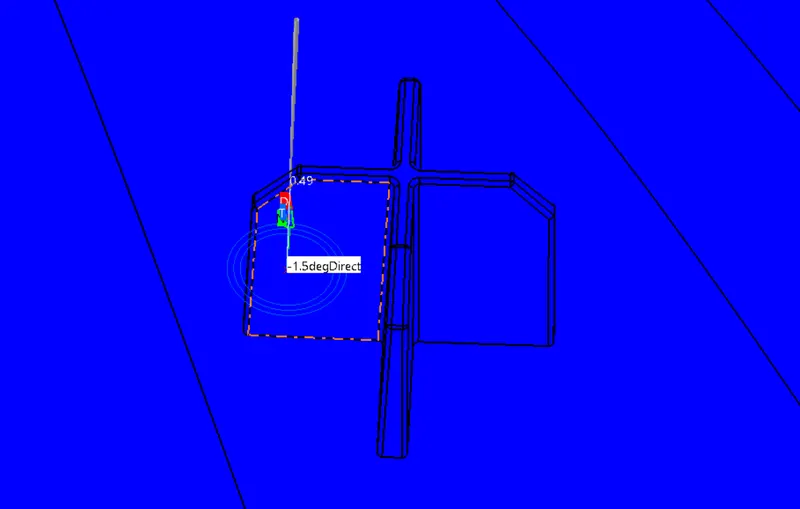
The Draft that i have provided with locator is 1.5 degree which is ok and also provided with the proper entry chamfer.
Heat Stakes
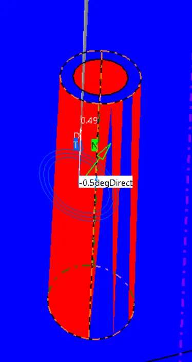
Heat Stake is showing like this but the draft angle is proper which is 0.5 which required in this. So it is ok and the problem is with the catia version.
Addition Information
The additional informtion about this corner which is showing below
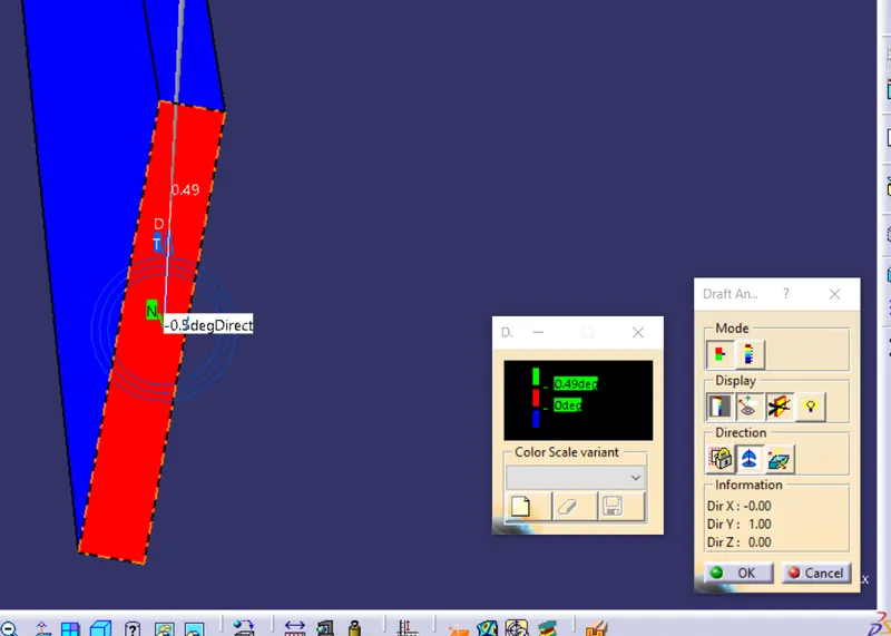
It Should be in blue color but it is showing in red color so the same problem with catia version but the angle is 0.5 we can see using the pointer.
GARNISH
Class A Surface for the Garnish along with draft analysis
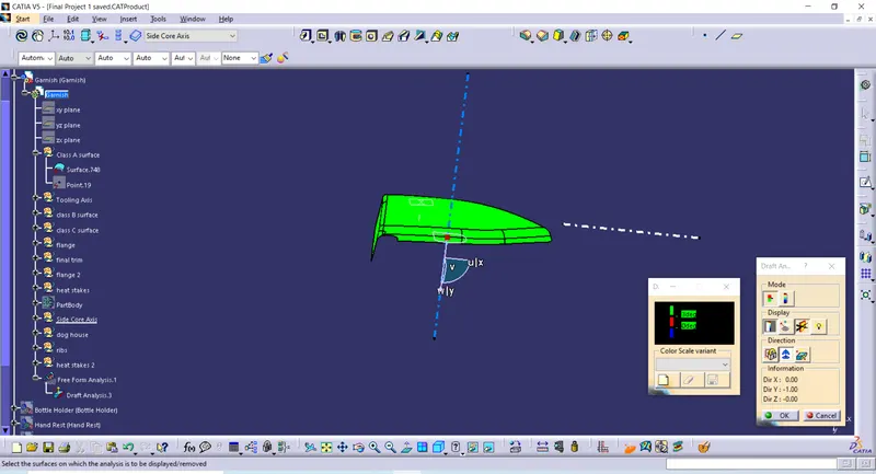
Hence the Above tooling axis that i have selected is ok as they are showing green color every where.
Class B surface
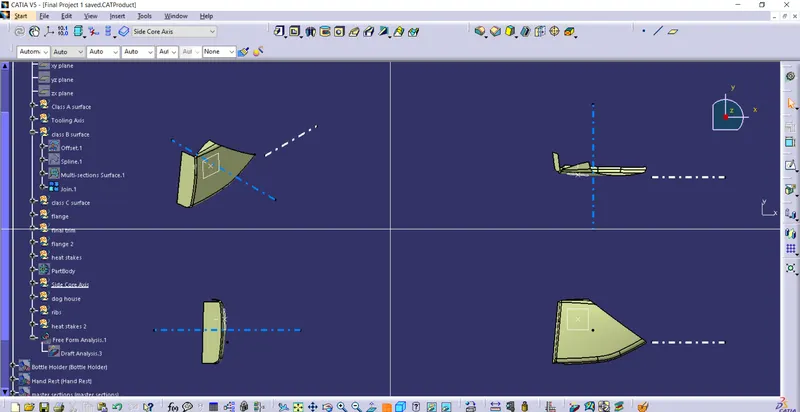
Class C surface
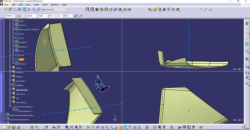
Class C surface Joined with Class A Surface is Above Pic.
- Final Solid Part
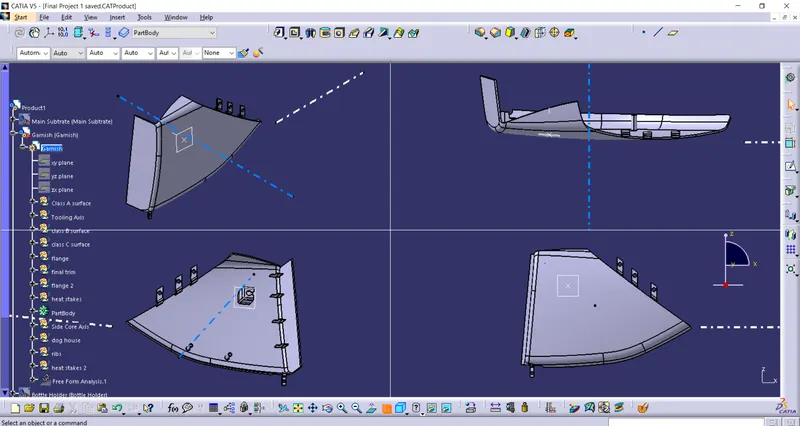
The Above the solid part along with the attachment features such as Dog house, Heat stakes and Flanges and ribs.
- Draft Analysis Report for the Garnish Part.
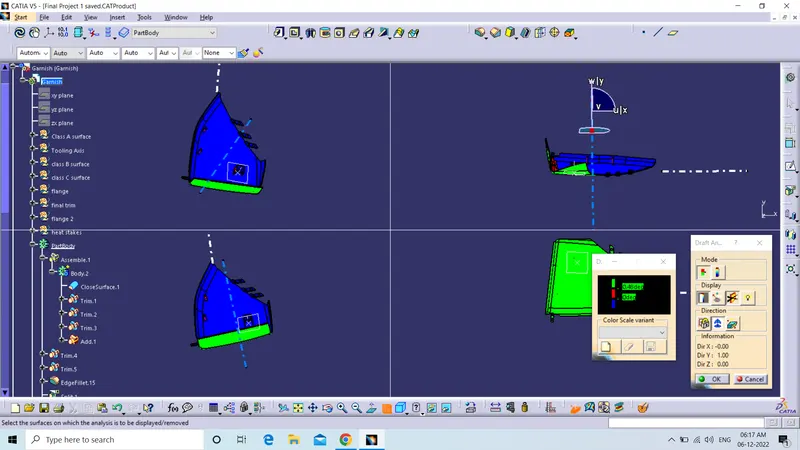
Draft Every where is above 0.5 degree. Will Show will using pointer in further Slides.
- For the Dog house
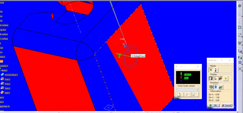
It is showing in red color but the draft angle is above 0.5 degree. It is showing in red as there is an issue with my catia version.
Along the Side Core Axis For the Inside of the Dog House.
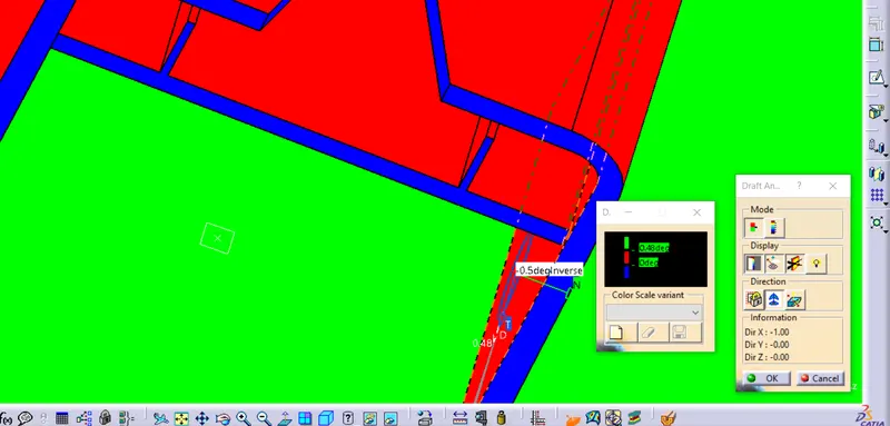
Walls with 0.5 degree draft
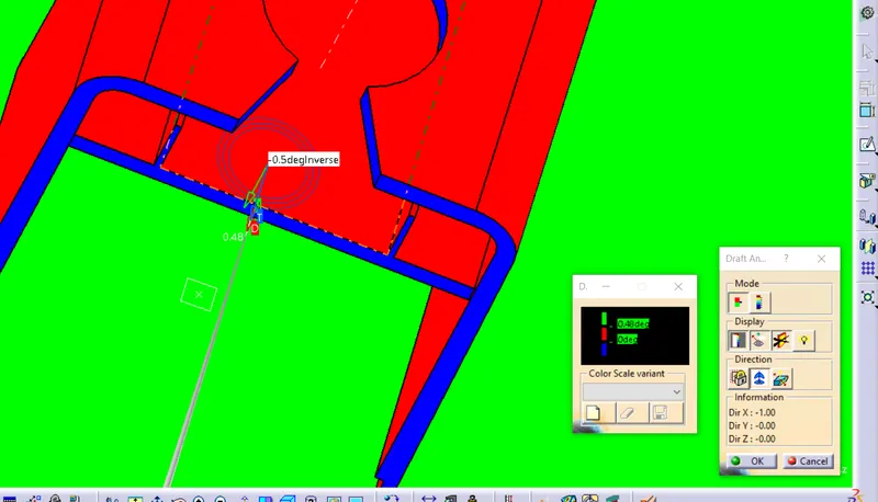
Ribs with the 0.5 Degree Angle.
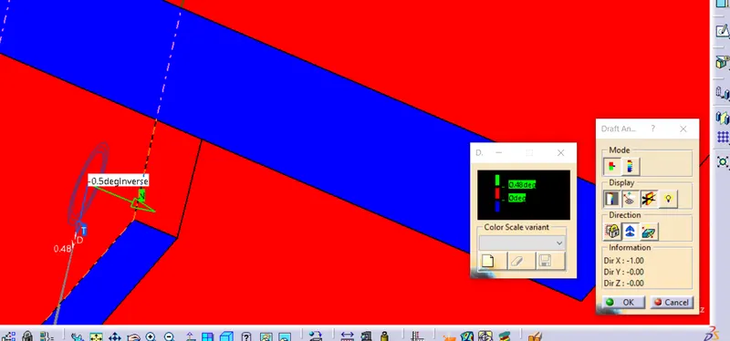
0.5 degree fromt he inside of the dog along the side core axis.
- Heat Stakes
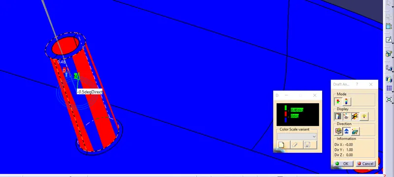
Same Thing here showing in red color but the draft angle is proper every where.
- Flanges
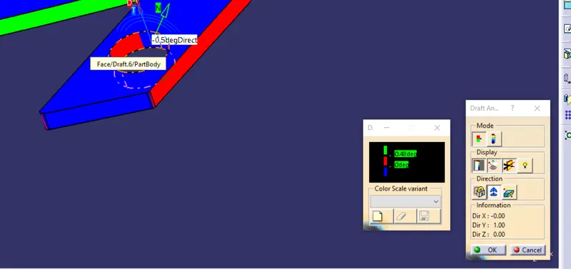
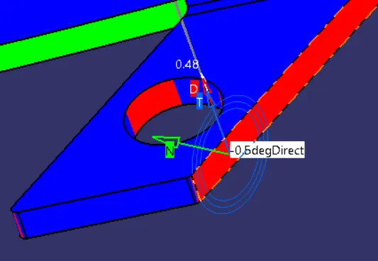
In both the Slides above the draft angle is 0.5 degree which ius proper. Issue is due to catia version.
- Ribs Draft Angle
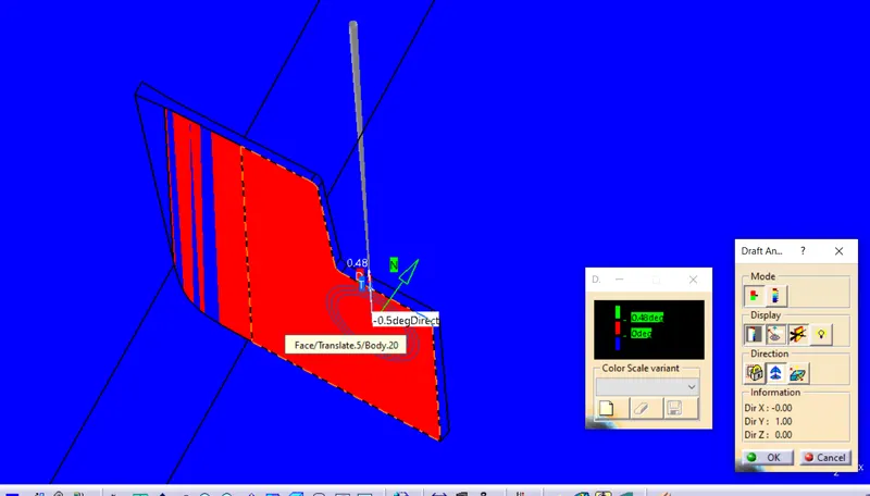
In the ribs also the Draft angle is proper as we can see in the above slide the angle is 0.5.
The Draft Angle every where with respect to the Tooling Axis is Proper. So the Tooling direction is justified.
- Bottle Holder
Draft Analysis of the Class A surface
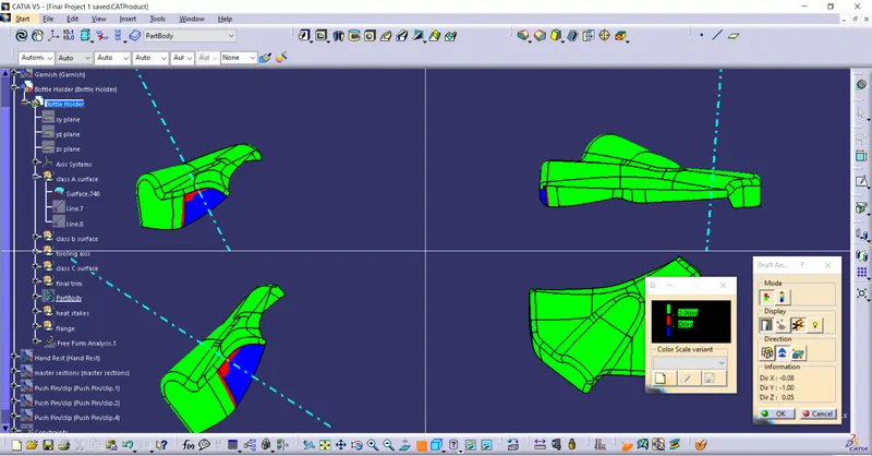
The Draft analysis shows some area with blue and red color. This is the most i was able to do as i have used bisecting method here and tried to change the angle still the time it again starts increaseing this type of area. So there is some issue with the class A surface.
- Class B surface
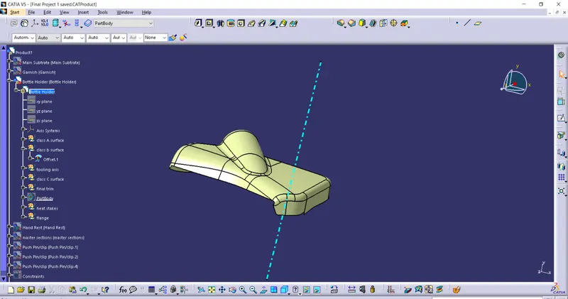 \
\
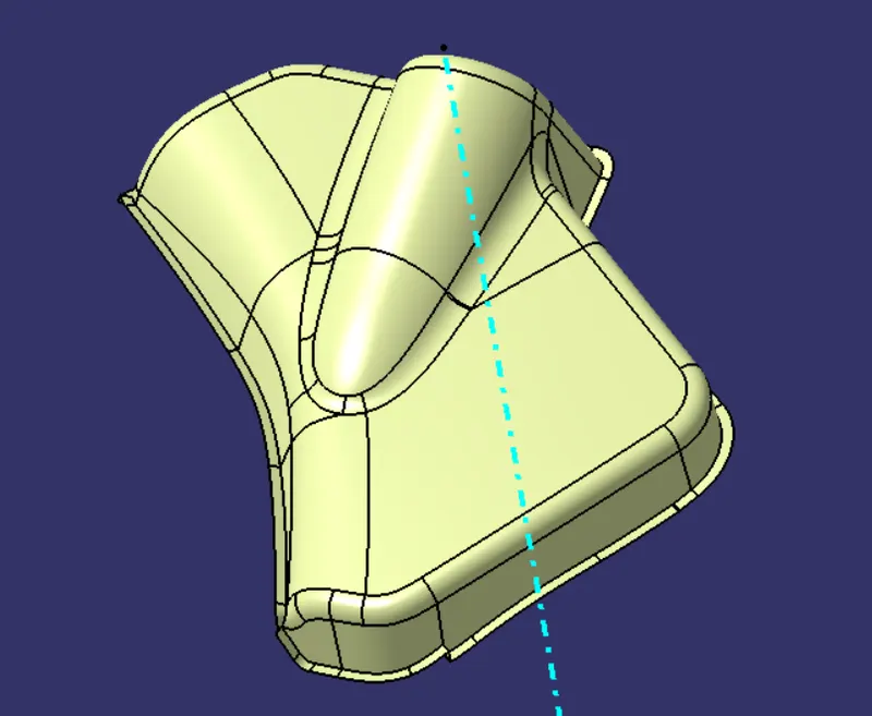
- Class C surface with Class A surface
- Draft Analysis of the Solid Parts
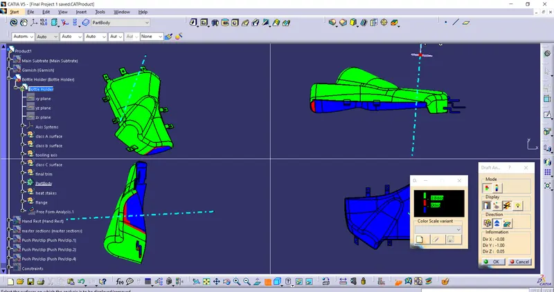
The Area with the issue in the class A surface has same issue in the solid part. Hence the area is is not under our control as we are not allowed to touch the class A surface. The other is okay in class B and class C surface also. Hence it is the Proper Tooling axis.
- Hand Rest
- For hand rest we have to update the class A surface as the class A surface is not proper as there is a gap between the surface
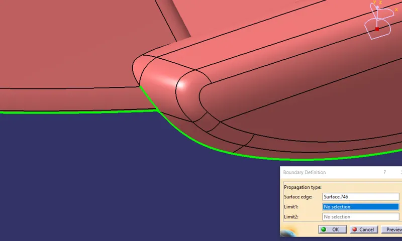
The Boundary is not Ok. So have to Modify the class A surface.
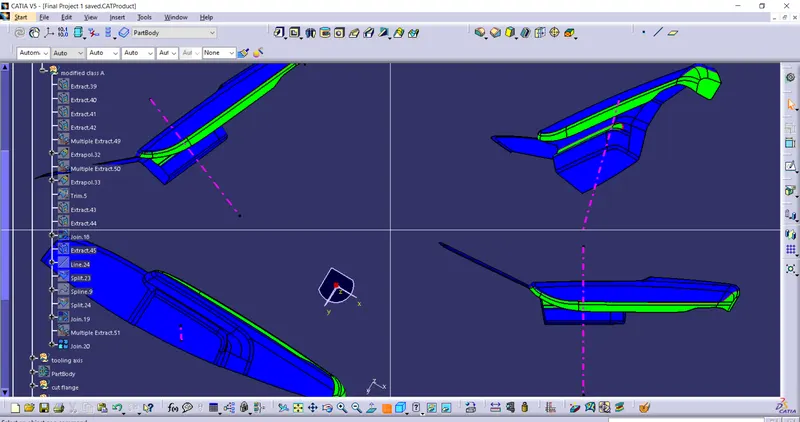
The area with green color is not showing proper draft angle when angle selected minimum 0.5 degree which means the class A surface needs correction and the draft provided to the class A surface is not ok.
- Draft Analysis of the solid part
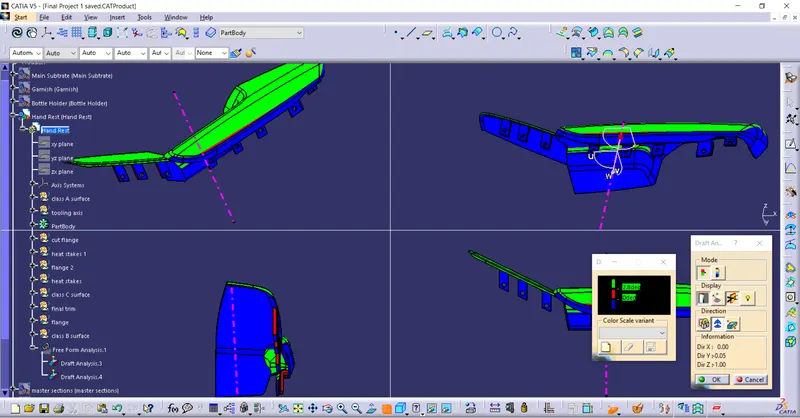
The Area with the issue in the class A surface has the same issue in the Solid part. The other class A solid part is ok here.
- Final Solid Part Assembly
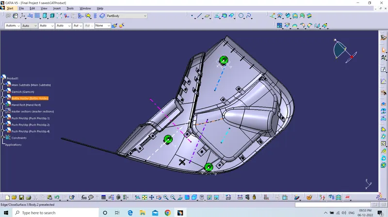
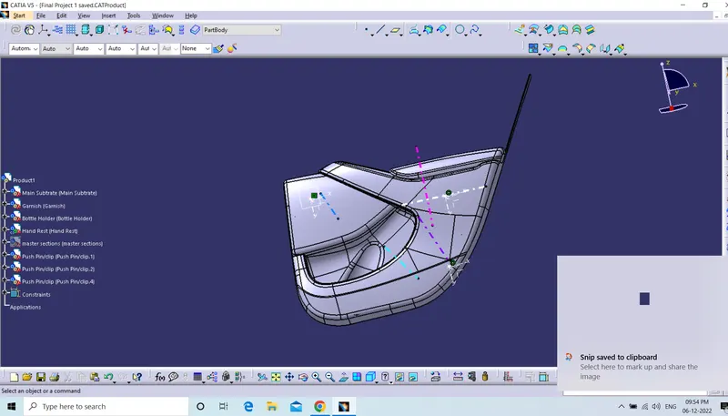
- The Push Pin is also attached to the Dog House using the constraints. As Shown in fig. below.
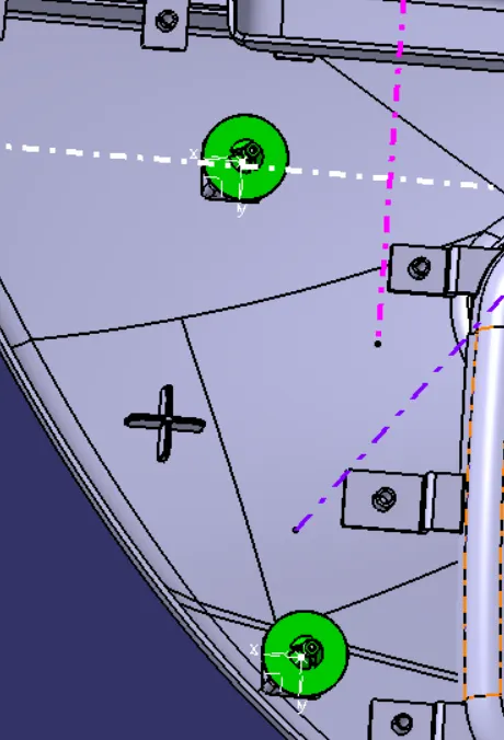
The Above is the whole Assembly of the Door Trim with the all required engineering features. Thank You