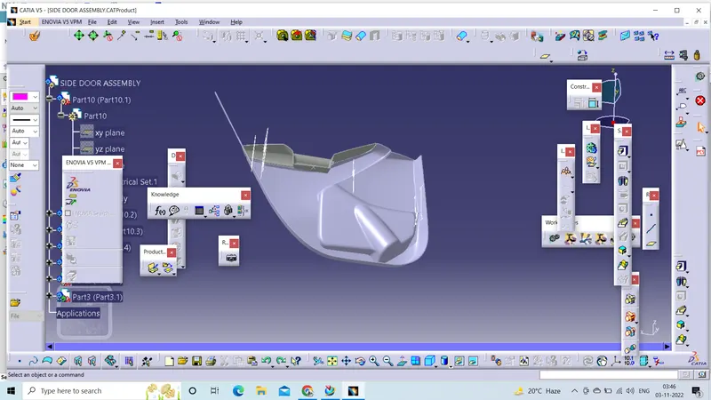
Week 11 - Final project
|
Development of a Door Trim panel |
Aim:
Creation of CAD model considering CLass A surface, nominal thickness, and attachment features.
Abstract:
The project report explains steps and procedures followed while developing the Door Trim Panel of a car using CATIA V5. Using the CLASS-A surface and master sections as input, we were able to create a Tooling axis, CLASS-B surface, CLASS-C surface, Flanges and form a solid body after which the attachment features such as Dog House, Push Pins, Heat stakes, etc are created. To check the manufacturability of the parts, a Draft Analysis has also been performed using the main/side tooling axis on various components such as lower substrate, map pockets, armrest, etc.
Objective:
Creation of CAD model considering following inputs as like in OEM and tier1 companies
- Class A surface
- Nominal thickness: Refer to master sections
- Attachment strategy: Flanges, Heat stakes, and Dog house.
Detailed report:
Method followed:
- Class A modification of given Class A.
- Creating A Class B and C surface.
- Create Thickened part using the master section for reference.
- Create the mounting features as per design guidelines in the industry and with master sections.
- Performing a draft analysis.
Procedure:
1. Modifying a given class A surface by extracting it
From a given class A we have separated the class A of Lower substrate, Map pocket, and Door armrest.
- Lower substrate:
1. Lower substrate:
To get a Class B,
First of all, we offset the Class A on 2.5mm in the required direction. For intersecting Class B with Class C, we need to extrapolate the offset of Class B.
Next, we need to make a Class C from Class A so we just use a sweeping command with a reference surface of 87 degrees draft angle with the required direction.
Got some issues during sweeping especially on a curved surface so we make Multi-section surfacesIf there are any intersecting boundaries on the surface we use the JOIN command and add SUB ELEMENTS TO REMOVE and use Multi-section surfaces to fill the surface.
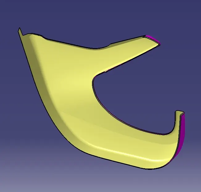
Then we checked the boundary of the surface of Class B to make sure that the surface has no boundary on the surface so it will not create a problem while trim Class B and Class (A+C) surface.
After that, we joined the Class A and C surface and trim it with Class B Surface
Finally, we get the closed surface output of the Lower substrate.
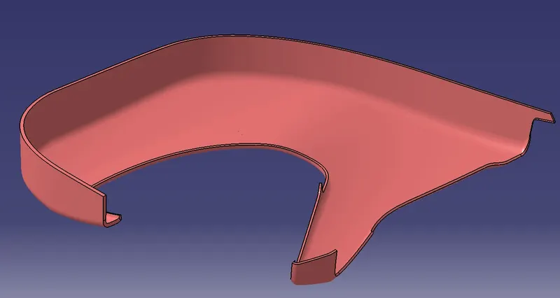
Similarly, we did with Map pocket and Door armrest.
2. Map pocket:
Here we divide the Outer map pocket and Inner map pocket by extracting them separately.
- Outer map pocket:
First, we offset the extracted Class A for 2.5mm distance which is the minimal thickness of the component.
Next, we extrapolate by adding edges in the command of Class B to intersect with the C surface.
Then give Multi-Section Surfaces where extrapolate is not working especially in curved sections.
After that, we used to sweep concerning the Class A surface at 87 degrees by visualizing which direction we needed to sweep the surface.
- Inner map pocket: we did the same operations which are followed for the outer map pocket.
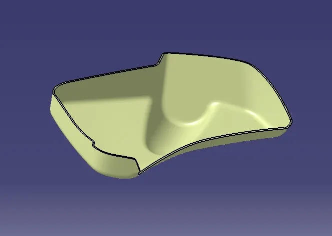
3. Door armrest:
In, Door armrest we divided it into parts by extracting it separately and worked on it to neglect the error on the Class B surface.
We have done the same operations on door armrests which apply on map pockets and the lower substrate.
Class A and B surface:
- Create a solid body using the master section for reference:
First, we go to the part workbench, next create a new body then use a close surface feature and finally we get our final output of a nominal thickness of 2.5mm measured from master sections.
Lower substrate
- Creating the mounting features as per design guidelines in the industry and with master sections:
- Flanges:
First, we extract the curve that lies on the body
Next, we make a point on it and use a point repetition operation with the distance between 60-100 according to the design rule for flanges
Then add the plane and sketch the flange and constraint it.
After that go to the part workbench and pad this sketch on a mirror extending with a thickness of 2.5mm.
Finally, we get the flange now we copied it and paste it with the link and transfer it point to point.
Give a draft of 3 degrees.
- Heat stakes:
First of all, we made a point on the surface in the middle of both sides.
Next, I need to make a plane by offset from the plane then make two circles of D10 & D9.4. Bigger circle for making a hole on a flange and another one is for heat stake.
Make sure that the distance between the heat stake and the surface of the flange should be 0.5.
Extract both circles separately and extrude the bigger one.
Go to the part workbench and split the extruded circle from the flange so that we get a hole for the heat stake.
After that take a small circle and pad it with a thickness of 1.5mm. Pad it up to distance so it can get to the other side of the lower substrate.
Give a draft of 0.5mm and make a point reputation on the same line next copy-paste it especially with the link.
Then add all heat stakes in different bodies and name it as a heat stake assembly and union-trim it with a lower substrate.
- Dog house: It is a ‘doghouse’ looking embossment for screws to attach one piece of plastic to another one. For example, you have a bumper cover, and you want to add a garnish to it. You would use doghouses to do so.
The dog house is created by operations given below,
- Extract the base.
- Make a point and YZ plane on it.
- Create a C-section sketch and constraint it.
- Extrude the sketch and go to the part workbench and thicken it by 2.5mm.
- Make a line in the sketch, extrude it, and trim it to cut the dog house in the required dimension.
- Split the surface to the dog house solid
- Give a draft of 0.5 degrees and edge fillets of R1 and R3 by measuring it on the master section.
- Avoid sink marks: The box's inner walls are extracted and offset by 1.2mm to the outer side in a shape generative workbench.
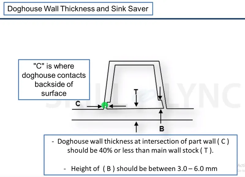
Then, the base A surface is intersected with the vertical back surface of the dog house to get the lines that will be cut out and this profile can easily be covered with a side core or lifter axis.
This profile is extruded and later trimmed with the offset surface to get the final lower cut out. Lastly, the cutout surface is split with the thickened dog house to obtain the final dog house.
Then, the fillets and draft angle of 0.5 are provided to the dog house. But the inside surface of the dog house is drafted in the direction of the side core tooling axis.
- The dog house should be 50mm apart from the side surface of the lower substrate.
- Pushpins: Pushpins are used for fixing two components.
Make a point on the dog house and add an offset from the plane.
After that, sketch it and extrude it so we can split it with the dog house to make a cut section for the pushpin.
First, we create a sketch on the dog house next to the part workbench then use a revolve command and revolve it from the center axis after that and add it to the lower substrate.
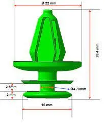
- Performing a draft analysis from the side core (Lifter) axis and main tooling axis:
To perform draft analysis, Go to the insert > Analysis > Feature draft analysis.
Switch customize view parameters and select material.
Click on the compass icon and align it with the tooling axis & click on the surface, we will get our results.
From the below image we can see that the surface in green color has more than 3° and 0.5° for dog house and ribs draft which is most required for tooling feasibility. Also, see the color variant display box.
MAIN TOOLING AXIS DRAFT ANALYSIS:
LOWER SUBSTRATE:
Result & Conclusion:
A Door Trim Panel with engineering features using the master section and styling surface as an input has been successfully created and draft analysis has also been performed for the same.