Week 11 - Final project
Aim:- Development of a Door Trim panel
Creation of CAD model considering the following inputs as like in OEM and tier1 companies
- a) Class A surface
- b) Nominal thickness: Refer master sections
- c) Attachment strategy :
Find an attachment strategy for the door panel complete work.
Use Push pin with Dog house for Lower substrate – Door panel attachment
Use heat stakes for part-to-part attachment
INTRODUCTION:
CLASS-A SURFACE: A surface made by the designer which is given as input to the plastic modeler/ sheet metal designer to work on. It is an aesthetic surface and the outermost surface.
CLASS-B SURFACE: A surface below a certain thickness from the class-A surface is a class-B surface. This is the surface that contains engineering aspects of a model for example Ribs cutout.
CLASS-C SURFACE: A surface that joins class-A and class-B surfaces together is called a class-C surface.
Draft Analysis:- Draft is a taper applied to the faces of the part that prevent them from being parallel to the motion of the mold opening. This keeps the part from being damaged due to the scraping as the part is ejected out of the mold, to do that the analysis is done and known as Draft Analysis
Tooling axis: The direction in which the mold or core and cavity open is called the tooling axis.
MASTER SECTION:
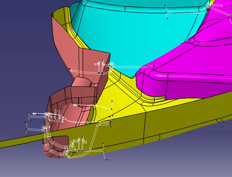
Master sections are the guides for design requirements which decide the component packaging after the styling surface
PRE-DESIGN CHECKS:
Before starting the creation of the class B surface we must ensure that the given class A surface is properly closed and the surface continuity is proper. This can be done either with the help of the join operation or by using the boundary feature.
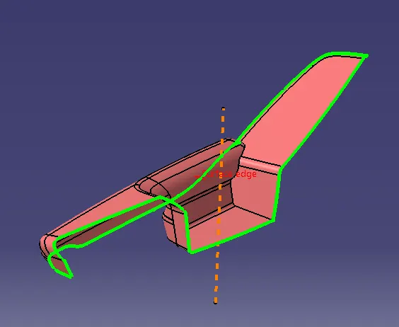
TOOLING AXIS:
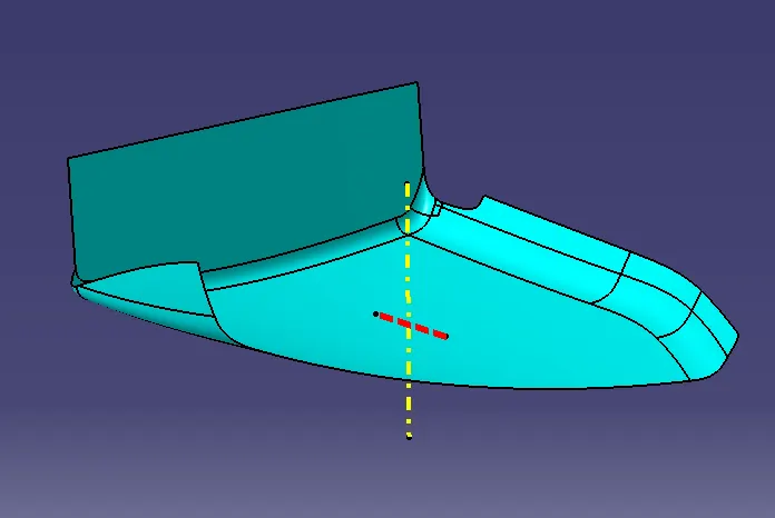
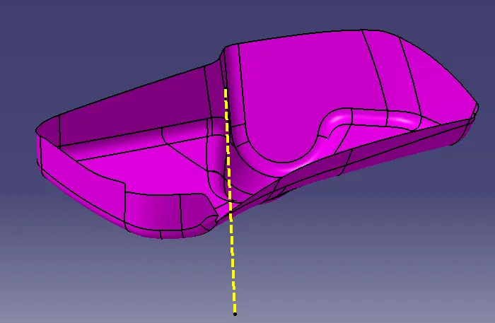
- The next step is to create the tooling axis for the part which will determine the direction in which the core and cavity of the mold will move.
- Designer must ensure that all holes and slots are covered in the main tooling and thus side core must be avoided whenever possible
- After analyzing visually for the best possible tooling axis, a reference tooling axis is created on the center of one of the surfaces of the armrest and other door trim components.
- The main tooling axis is created by using the bisecting method or by taking normal to the surface.
Arm Rest
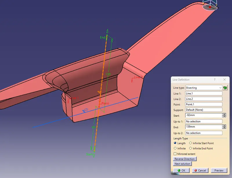
Lower Substrate
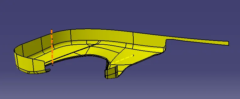
Upper Substrate
Bottle Holder
DRAFT ANALYSIS:
- Draft analysis is done on the class a surface after the tooling axis has been obtained
- The part must have a minimum draft angle of 3 degrees on all the tapered faces
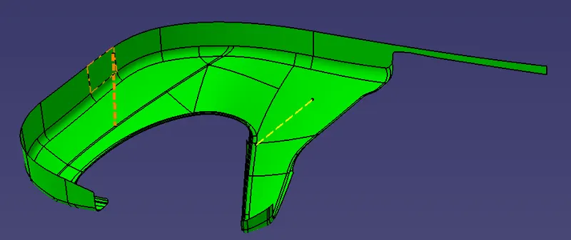
- Using the feature draft analysis tool and the compass the part surface is validated for the minimum draft criteria
Arm Rest
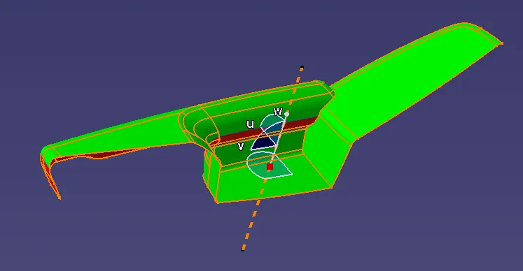
Due to Class A surface irregularity there are some areas which are blue/red to rectify this the Class A team need to be informed and coordinated in order to get the surface fixed
Lower Substrate
Upper Substrate
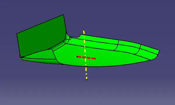
Bottle Holder
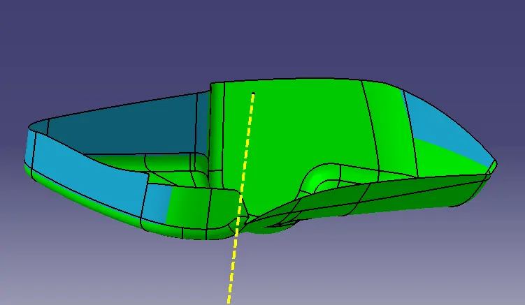
Due to Class A surface irregularity, there are some areas that are blue/red to rectify this the Class A team needs to be informed and coordinated in order to get the surface fixed
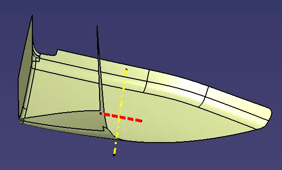
CLASS B SURFACE
- After all the validation has been done, the class B surface is created by offsetting the class B surface to a distance of 2.0 mm/ by following the master section provided.
- After offsetting a large opening in the surfaces is found which is closed with the help of sweep and multi-section commands
- The class B surface is then extrapolated in parts to trim it along with the class C surface
Arm Rest
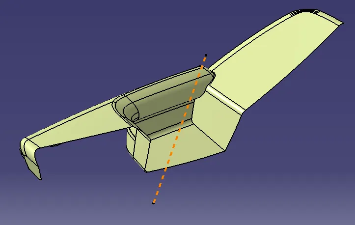
Lower Substrate
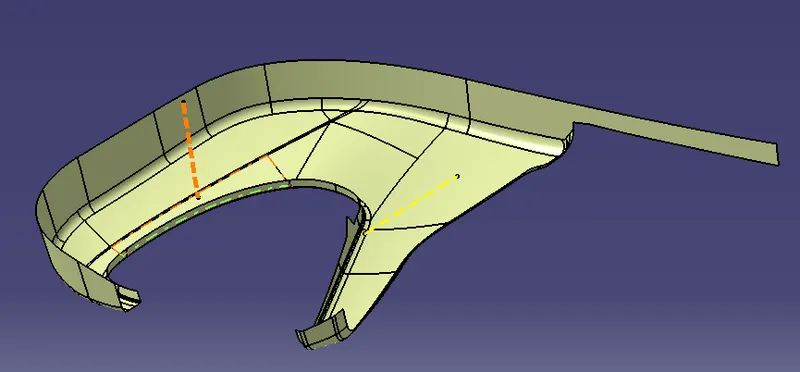
Upper Substrate
Bottle Holder
CLASS C SURFACE
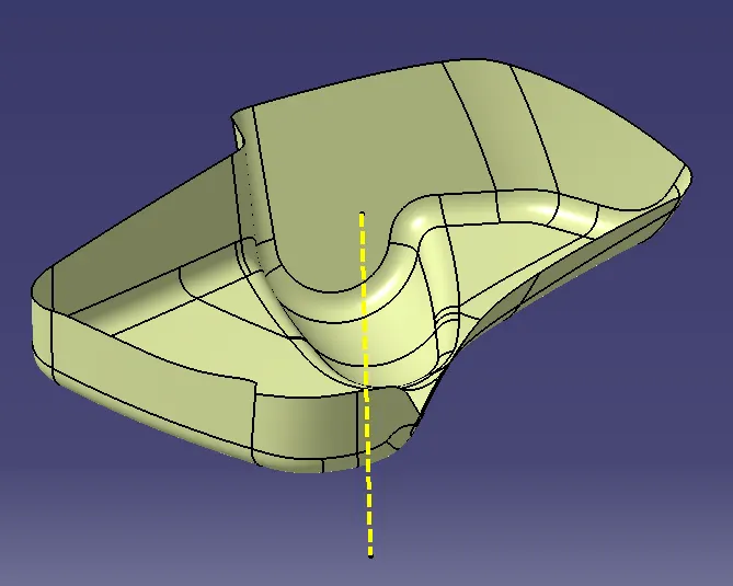
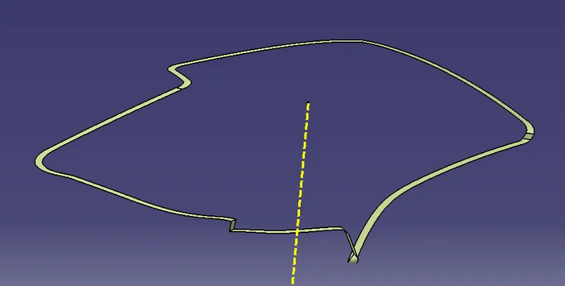
- The class C surface which connects the class A and class B surfaces is created by sweeping the boundary of class A and using class A as a reference.
- The sweep is divided into several parts in order to avoid complexity
- Surfaces that are parallel to the tooling direction are swept with the tooling axis as a reference and with a draft angle of 3 degrees
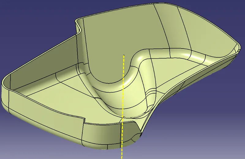
Class A + Class B + Class C:
After trimming we get the closed surface and then we go to part design and use the closed surface to create the plastic part
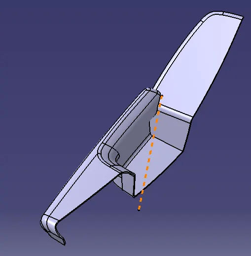
Arm Rest
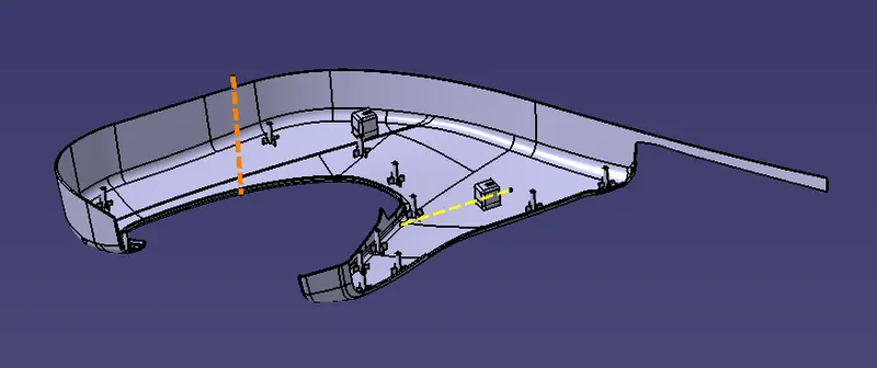
Lower Substrate
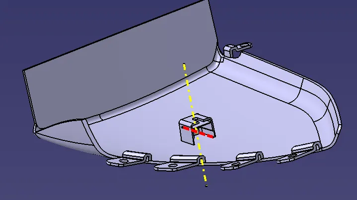
Upper Substarte
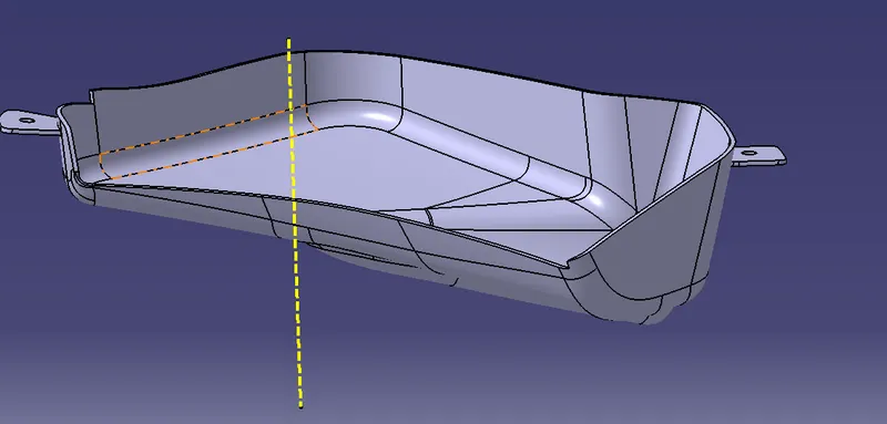
Cup Holder
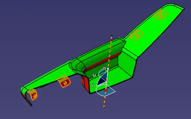
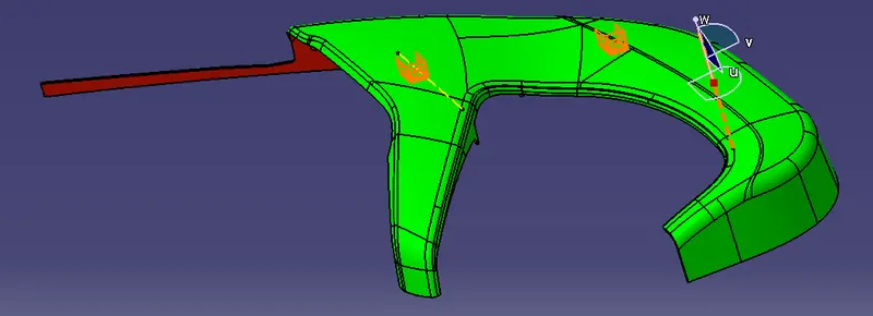
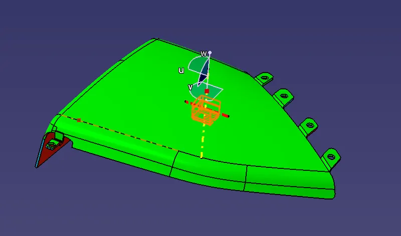
Draft Analysis for Solid Plastic Part
First the class – A surface is checked before creating the Class –B&C surface and finally the solid body must be analyzed. Both can be done by following the below procedures.
By changing the view mode to custom view parameters – Material mode then the feature draft analysis is enabled.
Then the compass was activated and placed with the tooling axis by dragging the red pointer and then locking it.
Then, by selecting the quick analysis mode, the nominal value will be 3 degrees and checked for the component's draft angle.
The green color area shows that it satisfies the 3-degree draft angle. If not satisfied then by using the Running point tool the area is measured and then altered to get a successful draft for the created tooling direction.
And due to Class A surface irregularity, there will be some areas not clearing draft so we need to communicate and coordinate with Class A design and present them with the issue and resolve the irregularities.
Arm Rest
Lower Substrate
Upper Substrate
Bottle Holder
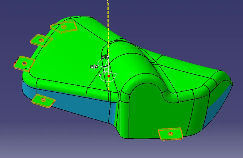
Due to Class A surface irregularity, there are some areas that are blue/red to rectify this the Class A team needs to be informed and coordinated in order to get the surface fixed.
B Side Features Creation
Dog House Creation
Design Principals for Dog House Creation
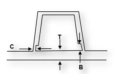
"C" is where the doghouse contacts the backside of the surface
-
Doghouse wall thickness at the intersection of the part wall ( C ) should be 40% or less than the main wall stock ( T ).
-
The height of ( B ) should be between 3.0 – 6.0 mm
The Surfaces That Are Cleared Along The Lifter Axis Are Also Given a Minimal Draft
-The Height Of The Attachment Walls Should Be a Minimum Of 3 Mm
-This Avoids The Plastic Defects On The B Side And Maintains The Texture Of A Side
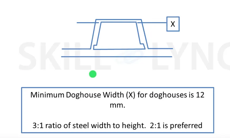
Procedure for creating the dog house
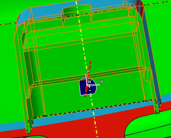
- First extract a face and create a rectangle and extrude it (Give direction as tooling Axis) and with shell command remove the face with a thickness of 2 mm.
- Give the draft of 1.5 degrees on the outer walls with the pulling direction as the tooling axis (make sure you cut the material).
- For inside faces make a tooling axis (Side Core) by following the same method and then give a draft of 0.5 inside (make sure you cut the material) and then extract the inner face.
- Extract the bottom surface and give an offset of 3-6mm and time with the side wall and then extrapolate the trim and then split the surface with the solid and then take a draft analysis after that provide a draft to the faces which didn't have to draft and provide the required fillets.
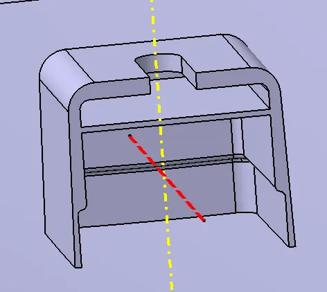
Draft analysis with tooling direction at 1.45 deg it is passing the analysis
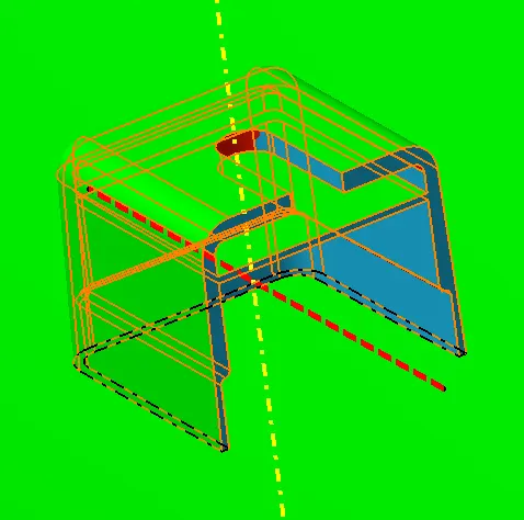
Draft analysis with Side core tooling direction at 0.45 deg it is passing the analysis
Heat Stakes design
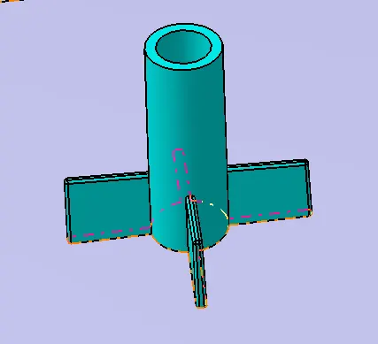
Heat Staking is a pulsed-heat process to join two or more parts out of which one at least is made of plastic. The process is to deform the plastic material using heat and force at a set process time. The bond is made by partially de-forming the plastic part in order to fix the other.
Design Consideration
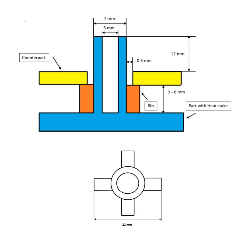
figure 1. heat stakes design
- Counter Part Thickness - Will be given as input
- Component Wall Thickness - Will be given as input
- Length of the Rib - 22 mm
- Height of the Ribs - 3 mm to 6 mm
- Inner Diameter of Heat Stake (d) - 5 mm
- Outer Diameter of Heat Stake (d) - 7 mm
- Minimum clearance between heat stake and counterpart - 0.5 mm
- Height of the Heat stake - Depends on the rib height and counter-part thickness
- Minimum fillet of Heat Stakes - 0.25 mm
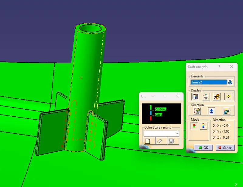
- Minimum Draft Angle of Heat Stakes - 0.5 degrees on both inside and outside faces
- Minimum 50mm Gap should be maintained between 2 heat stakes
- 0.5 mm clearance should be maintained for heat stakes and 0.1mm clearance for 4-way and 2-way locators
Draft Analysis of Heat Stakes
Flanges
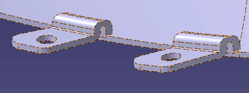
With the help of the given master section, we need to create the required flanges in order to join the Armrest, Lower and upper substrate and bottle holder together the master section is used and the sweep command is used to get the required flanges and to reduce the weight the flanges are split in a smaller size as the size is not mentioned in the task for flanges so the size is considered accordingly.
Attachment Strategy
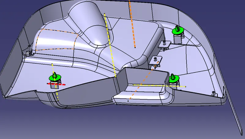
To attach the part of the door trim together we need to use the flanges and heat stakes and to connect it with the sheet metal part we need to use the push pin to connect and the design of the dog house such that it will insert the push pin and connect it with another side with the sheet metal component.
WEIGHT OF THE COMPONENT
- Apply material plastic to the product
- Use the measure command to calculate the weight of the product.
- Due to the lower version the plastics material is not applied and thus the overall weight is not calculated
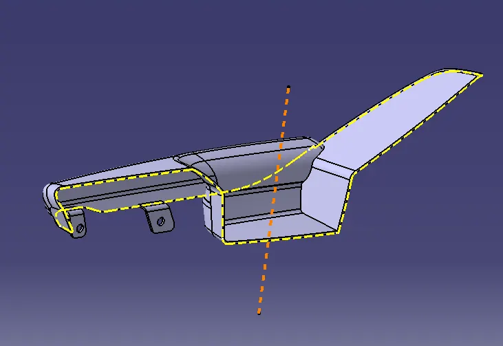
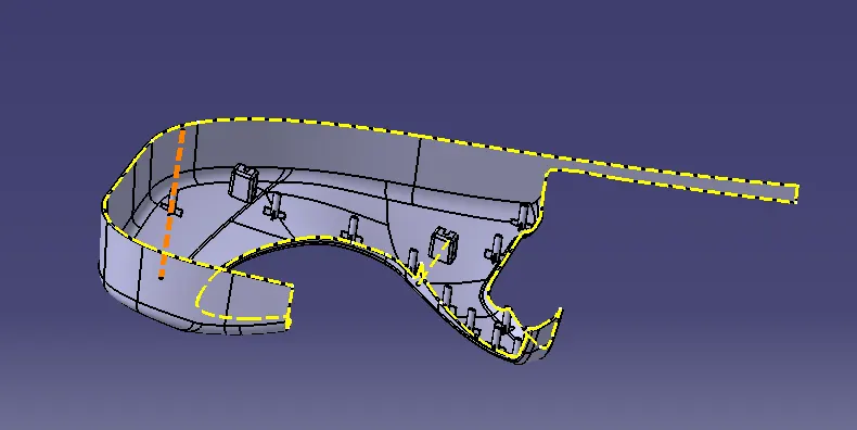
Creation of parting lines and checking tooling feasibility
The parting line indicates the direction of the line of the draw for the mold or the point where you can separate the two halves of the mold to release the part without damage
Arm Rest Parting Line
Lower Substrate Parting Line
Upper Substrate Parting Line
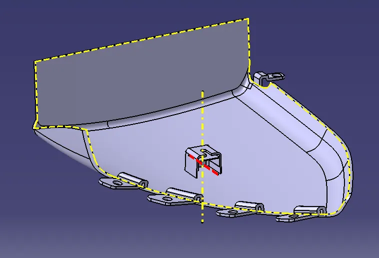
Bottle Holder Parting Line
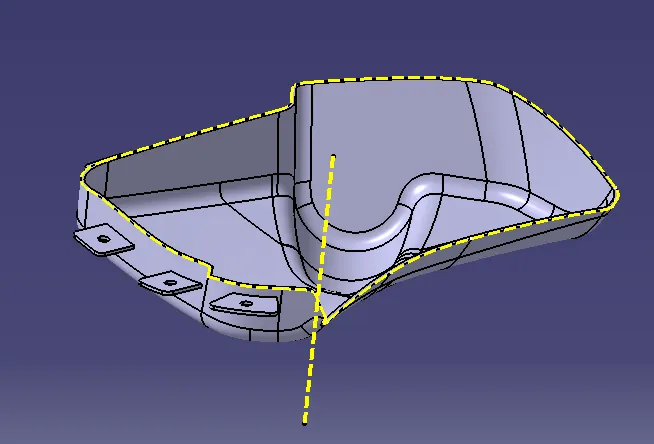
DOOR INTERIOR MODELS IN VARIOUS ORIENTATIONS
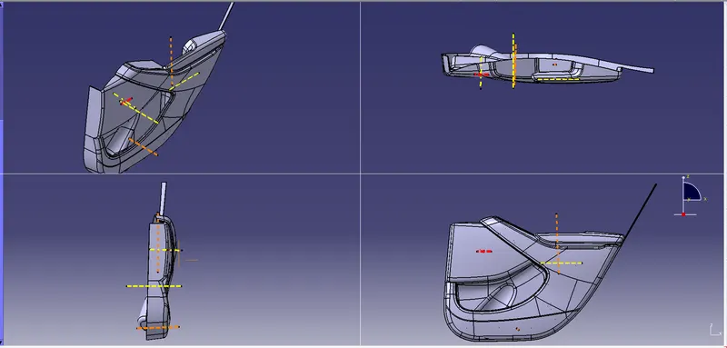
Front View
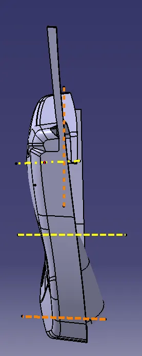
Top View
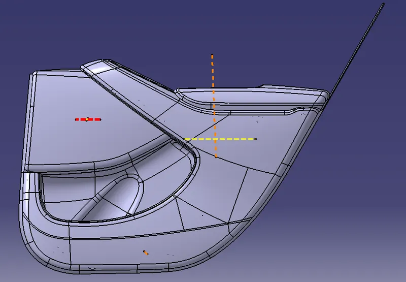
Side View
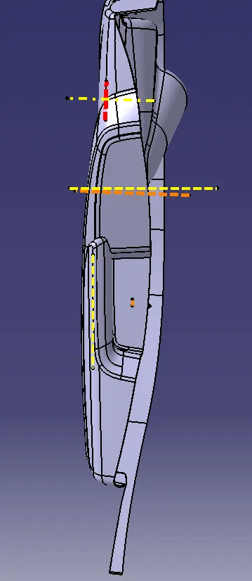
Isometric View
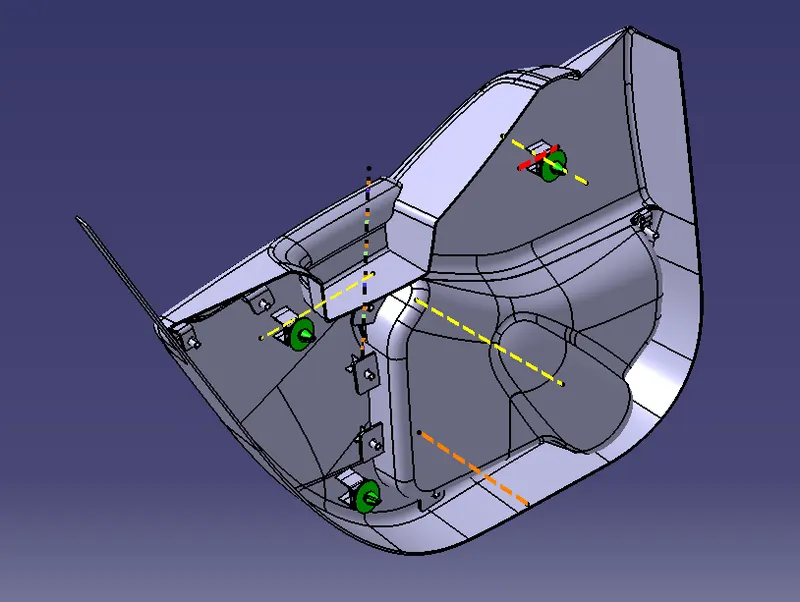
Conclusion:
Creation of the car interior door trim is designed using the given class A surface as the input and Class B and C surfaces are created with the help of the Class A surface. By using the given master section attachment features I.e. Heat stakes, Flanges, Dog houses, and Push Clips are created using the design rules. The draft analysis has been performed to analyze the draft of the component to manufacture easily applying draft to the surface by 3 degrees and 0.5 degrees to the attachment features. With all data and reports, we can conclude that draft analysis is very important to design any plastic component to mold the plastic easily. The analysis will verify that all surfaces are favorable for being pulled from a cavity. It may also highlight or give insight to defect areas.