Week 11 - Final project
Aim:
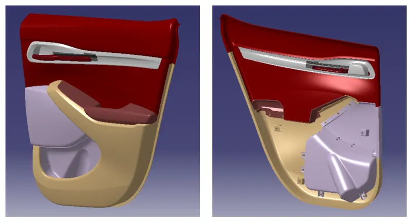
Creation of CAD model considering following inputs as like in OEM industries.
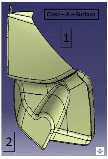
- a) Class – A – Surface
- b) Nominal thickness from the master sections reference
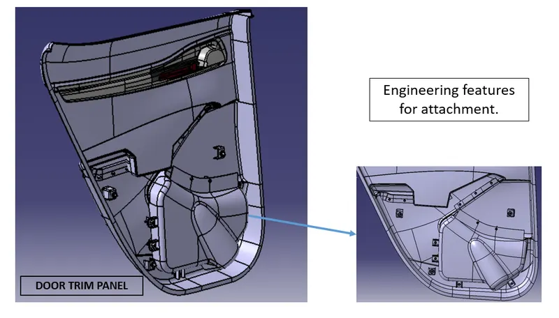
- c) Attachment features for the door panel,
- Heat Stakes for a part to part attachment
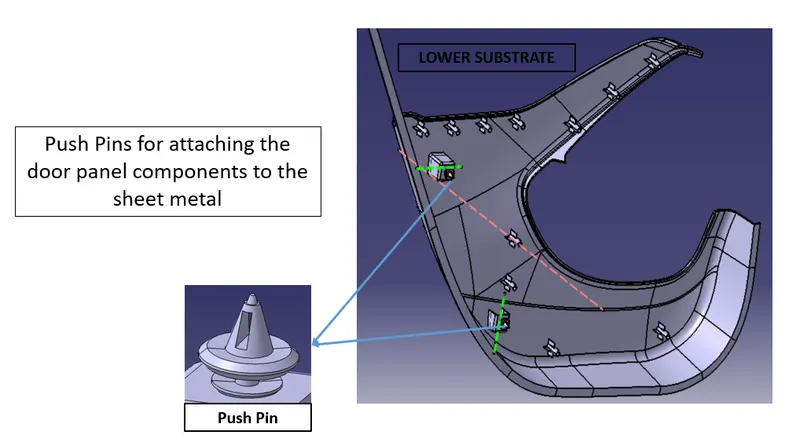
- Pushpin with dog house – Door panel attachment
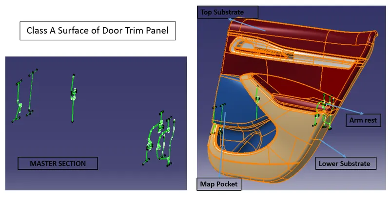
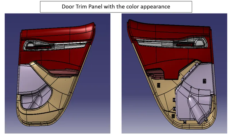
The following interior trims are designed in this door panel project,
Armrest
Lower Substrate
Map pocket
These components are designed by following industrial design guidelines.
Creating thickened part using master section for reference
- Import Class A Surface
- Creating Class B Surface
- Creating Class C Surface
Creating the mounting features as per design guidelines
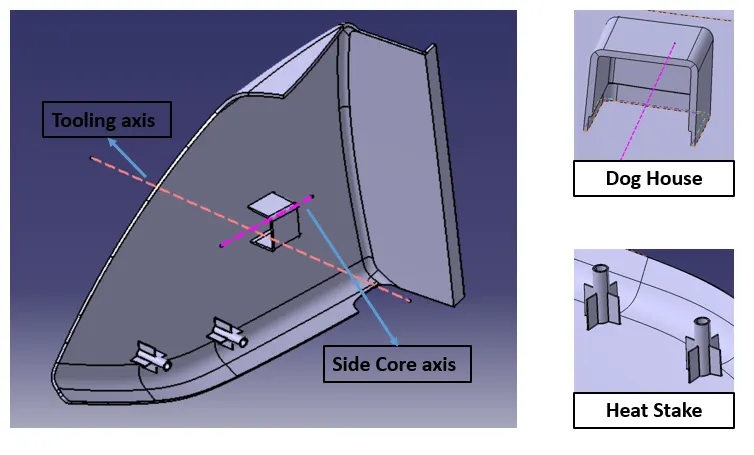
- Dog House
- Screw Boss
- Ribs
- Heat Stakes
Draft analysis
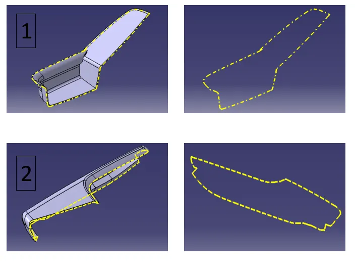
Creating Parting lines
ARMREST:
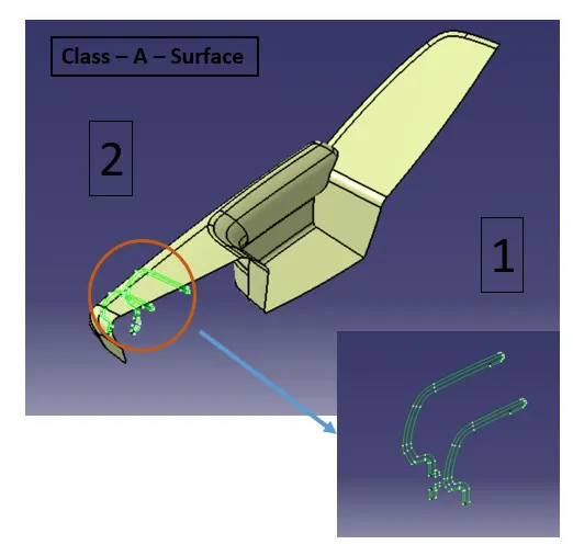
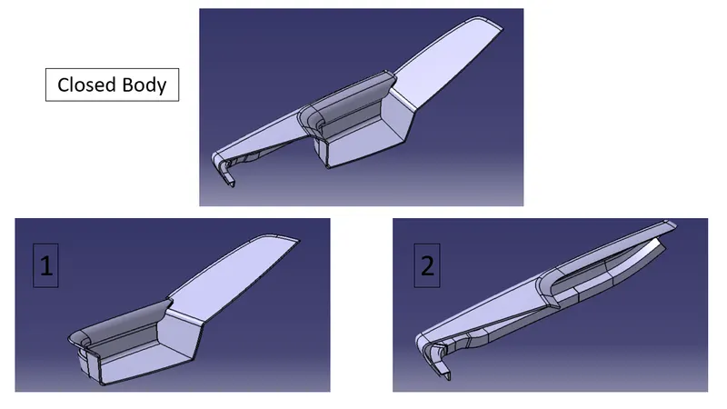
The armrest is divided into two parts.
Each part has a different tooling axis direction.
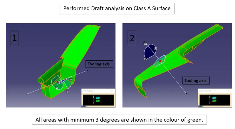
Determine the tooling axis direction by performing the draft analysis on the class A surface.
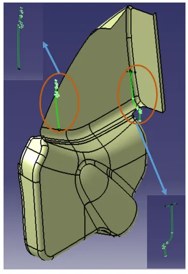
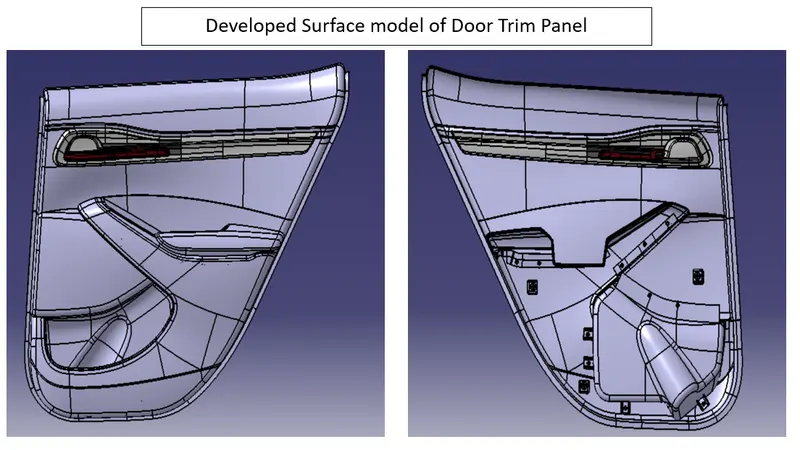
Develop the Surface model from the master section reference.
The thickness of the component is 2.5mm.
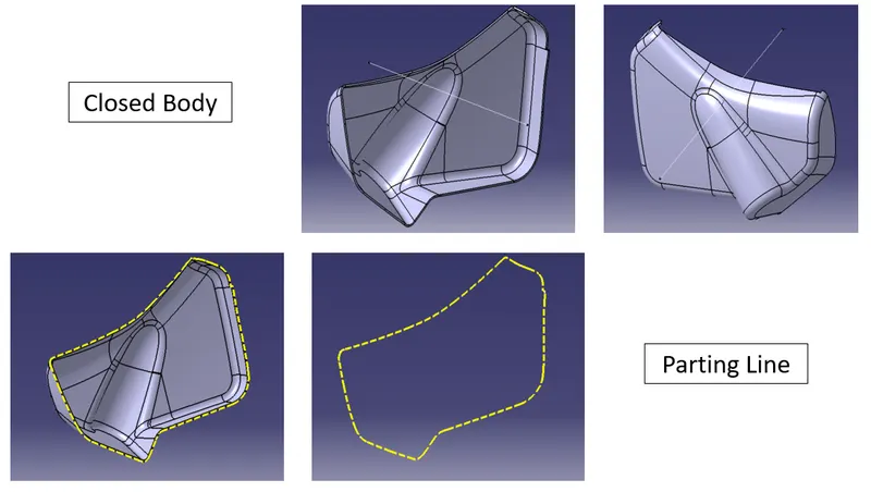
Parting Line:
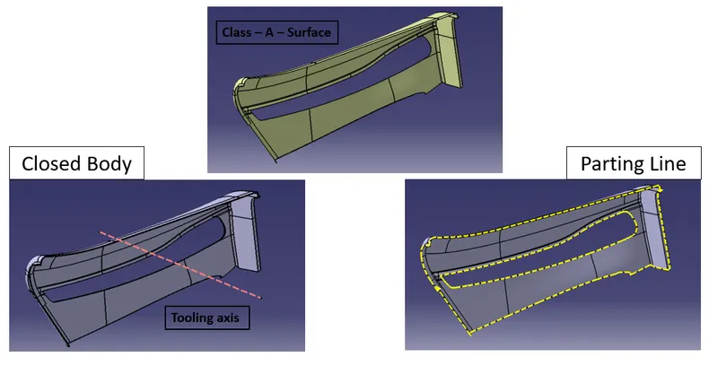
It is the borderline in which draft angles change direction.
This means it is the dividing line that splits the core and cavity halves of a molded part.
It is sometimes a starting point for the mold parting surface.
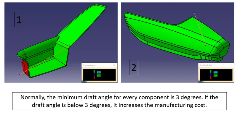
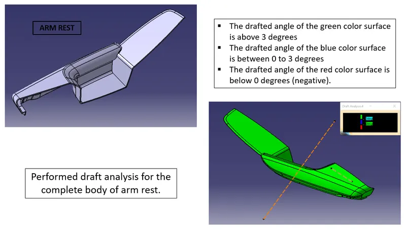
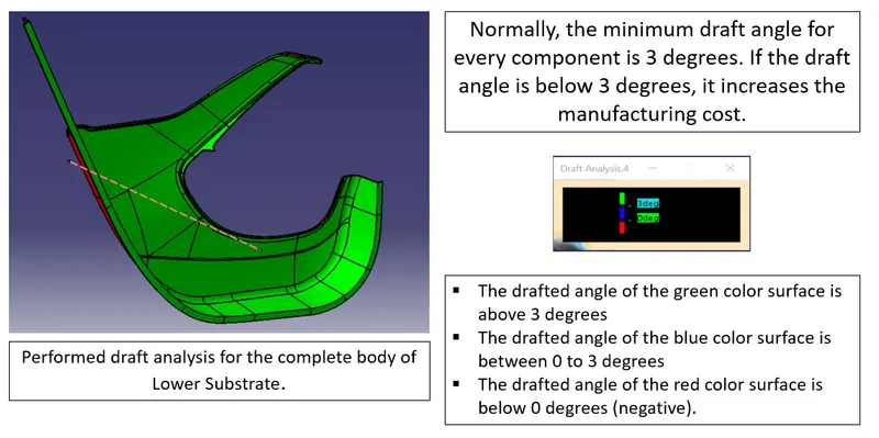
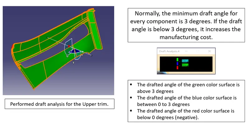
Determine the tooling axis direction by performing the draft analysis on the class A surface.
Develop the Surface model of the lower substrate from the master section reference.
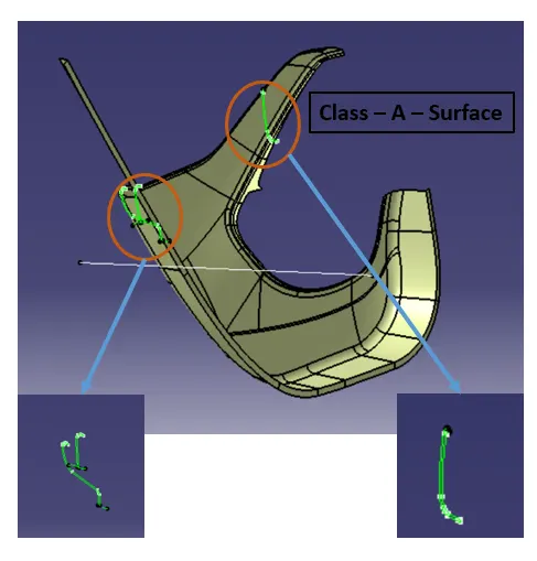
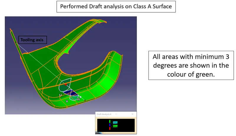
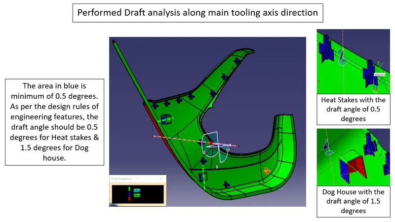
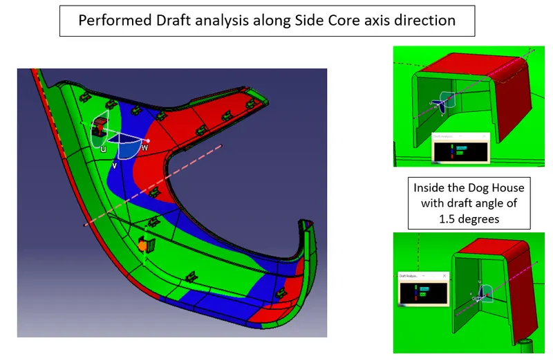
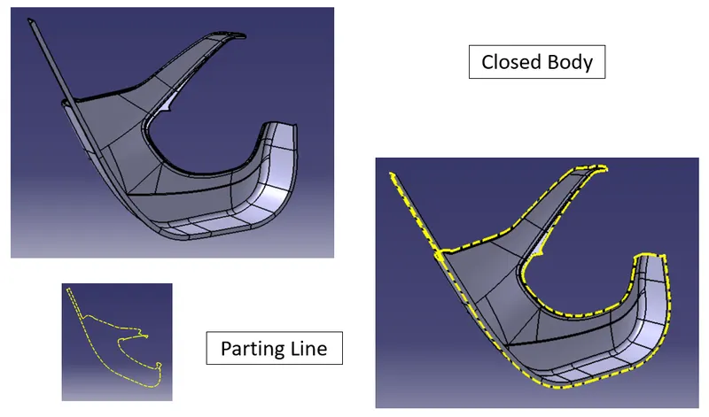 Draft Analysis
Attachment Features:
- These engineering features are attached to B Surface, which is also called an engineering surface.
- These features are designed as per industrial design guidelines to avoid plastic defects.
Dog House - The Primary function of the dog house feature helps to avoid the sink marks.
Heat Stake - It is also called Plastic Welding. In manufacturing products with thermoplastic components, it is often necessary to join a thermoplastic to a part of dissimilar material, whether it be metal, a dissimilar plastic, or other metal.
Ribs – These provide a means of economical stiffness and strength in molded parts without increasing overall thickness.
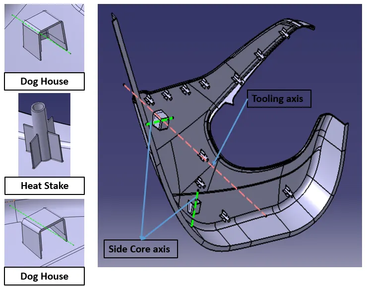
MAP POCKET:
Map Pocket is divided into two parts.
Each part has a different tooling axis direction.
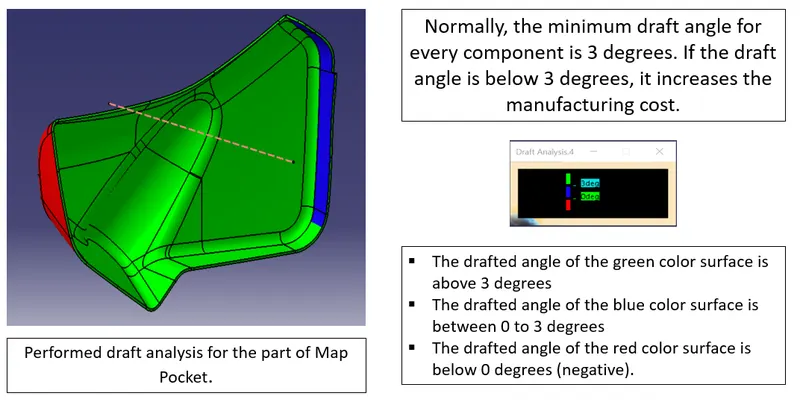
Determine the tooling axis direction by performing the draft analysis on the class A surface.
Develop the Surface model from the master section reference.
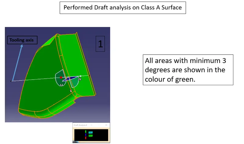
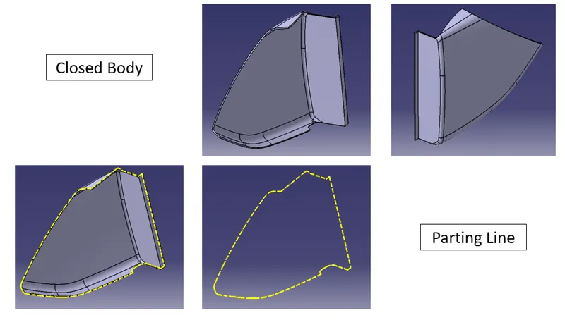
Draft Analysis
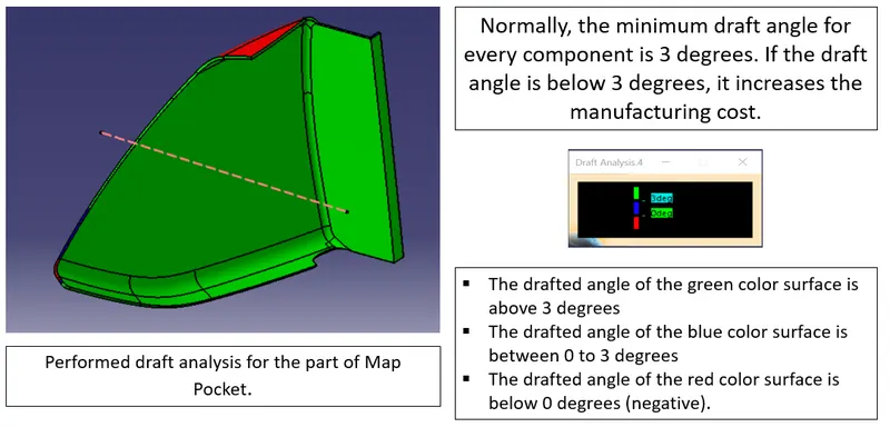
Attachment features
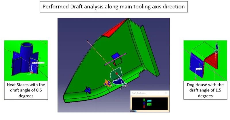
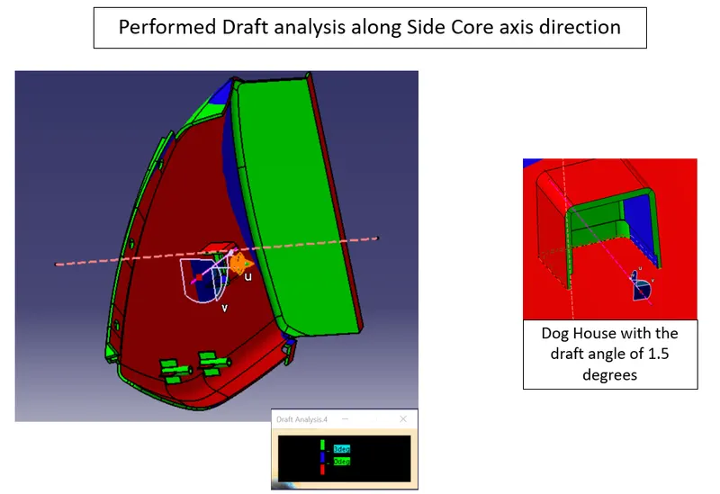
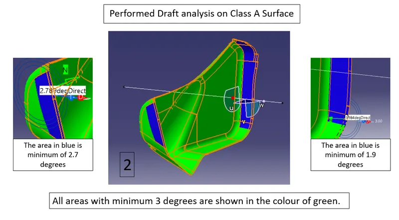
Draft Analysis
TOP SUBSTRATE:

.CATPART file and presentation ppt files are attached below.