Week 11 - Final project
Development of a Door Trim panel
Aim
- To create B&C Surface Far a Given A_Surface
- To develop all Engineering Features (Push clip, Dog House, Heat Stake, Flanges, Screw Boss) For a given component.
Note:- All Feature sketches and Thickness for the component are taken from the master Section.
Given Surface
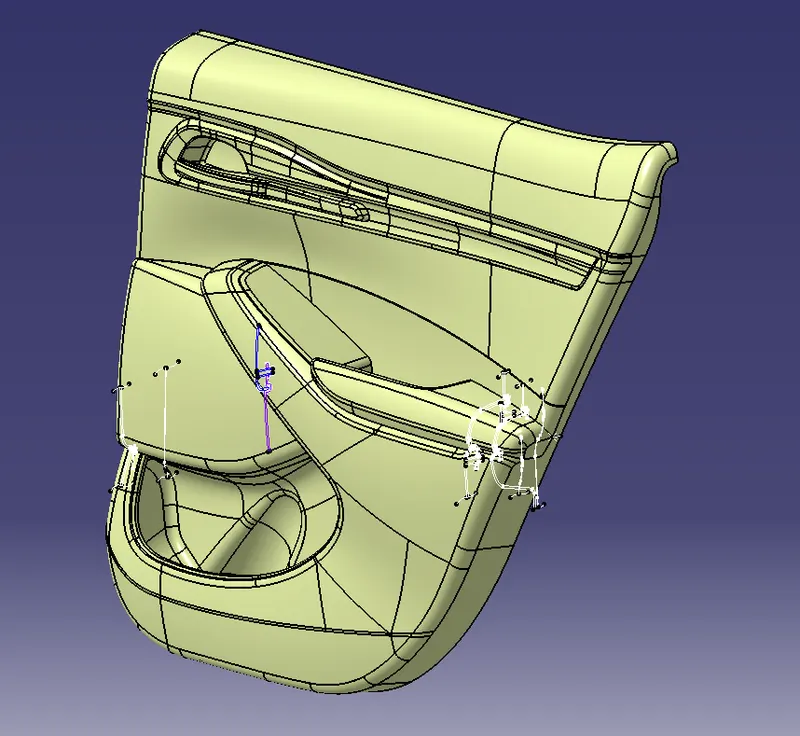
Developed Surface
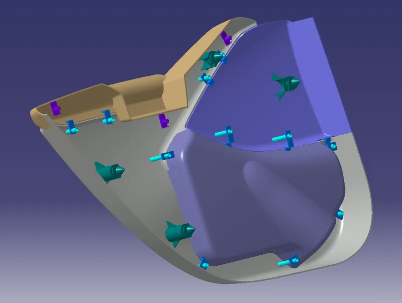
Tools Required
1 Surface Workbench Tools

2 part Workbench Tools

Sequence of Operation
1 Tooling Axis Creation.
2 A_surface Extraction & Checking Draft Analysis.
3 B&C_Surface Creation & Checking Draft Analysis.
4 B_side Features Creation (Push clip, Dog House, Heat Stake, Flanges, Screw Boss) & Checking Draft Analysis.
Procedure
1 Tooling Axis Creation
What is the Tooling Axis?
The Tooling Axis is the line that defines the pulling direction of the mold.
I create a 3tooling axis to clear the Draft for the component
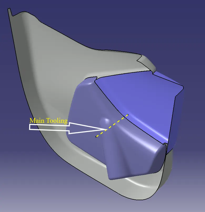
Tooling Axis For Map Pocket & Lower Substrate
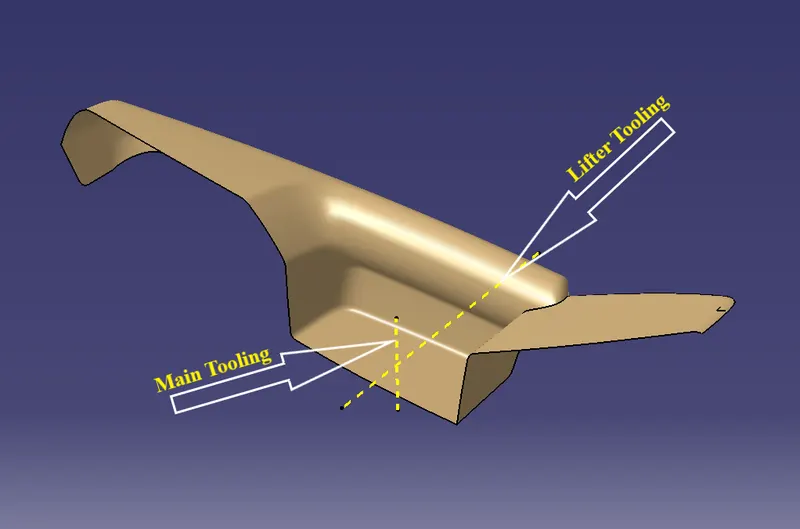
Tooling Axis For Arm Rest
2 A_surface Extraction & Checking Draft Analysis.
Before extracting the A_Surface let's Understand what is A_Surface and how it develops in OEM’S?
In OEM’S there is a Sequence of Operation for every product i.e Design life Cycle
- Concept Sketches
- Class A_creation
- Clay Modeling
- NPD CAD
The Concept Sketch team created a new design on paper ( freehand sketch) taken inputs from the Feasibility Check & Concept validation Team.
After approving the design the styling team takes place and create the A_Surface with the help of Allies Software
From there NPD (New Product Design) team design the component following all the design principle and engineering feature for the production by using different software (CATIA, SOLIDWORKS, NX, etc…,)
I divided the A_Surface into 4 Surfaces for the creation of B&C_Surface And B_Side feature those are Map Pocket, Lower Substrate, and ArmRest by using Multiple extract command.
I checked the boundaries and draft analysis with the tooling axis for the A_Surfacer.
Arm Rest
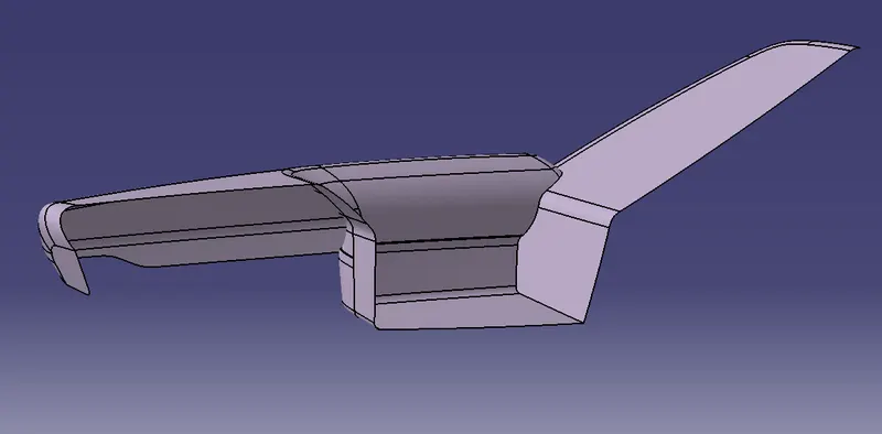
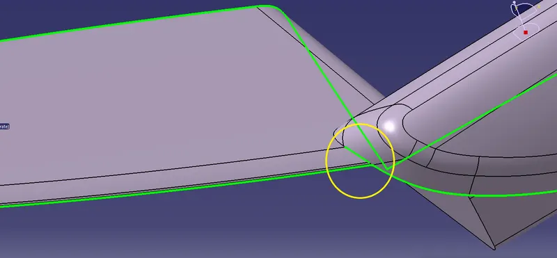
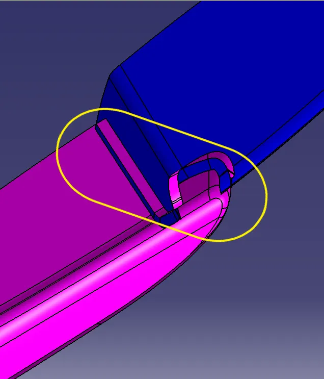
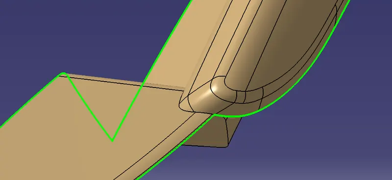
As you saw, in the image there is a boundary to remove that I extract the component into 2 sub-components and extrapolate the edge and make the trim to get a perfect A_Surface
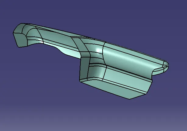
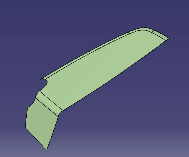
Draft Analysis
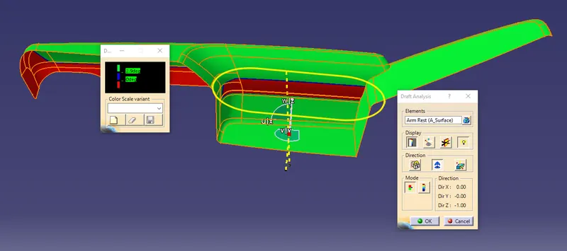
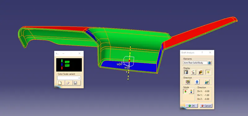
As you saw in the image in the main tooling axis the total component is not clearing the draft so we have to create a lifter axis to clear the faces
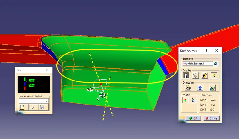
The total A_Surface is clearing the Draft Analysis.
Lower Substrate
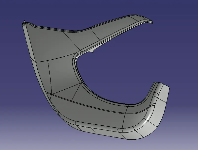
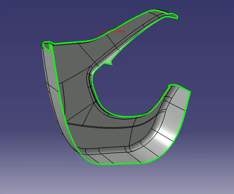
Draft Analysis
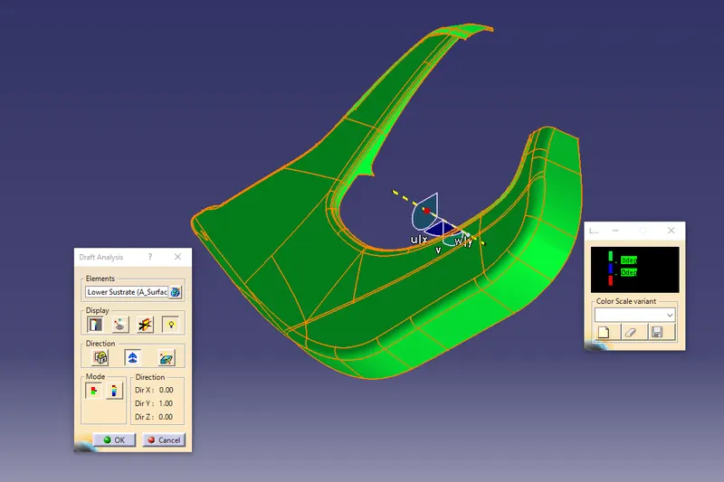
The total A_Surface is clearing the Draft Analysis.
Map Pocket
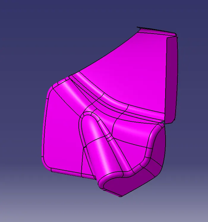
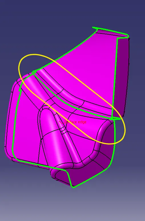
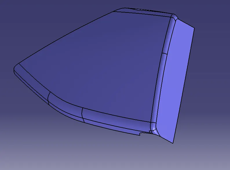
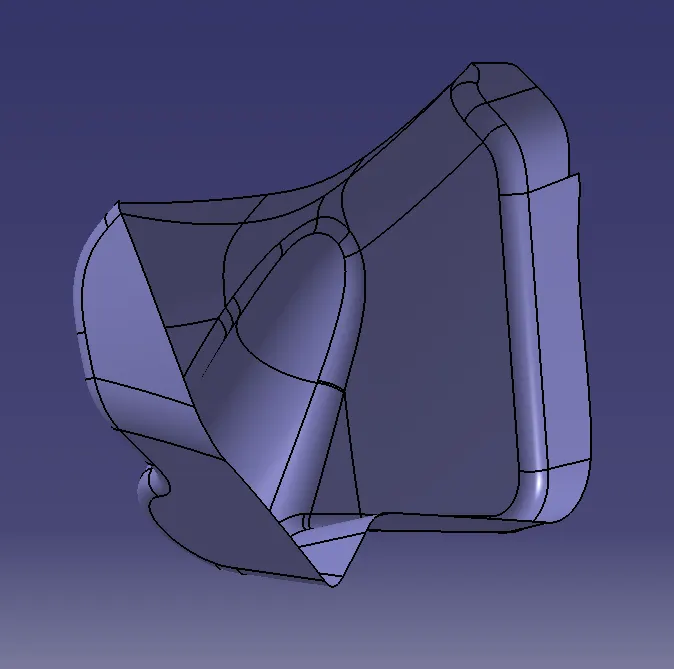
As you see in the image there is a gap and creating the boundary to resolve that I extract the component into 2 sub-components (Upper half & lower Half)
Upper Half
Lower Half
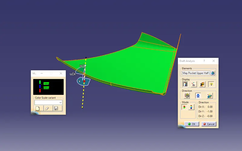
Draft Analysis
Upper Half
Lower Half
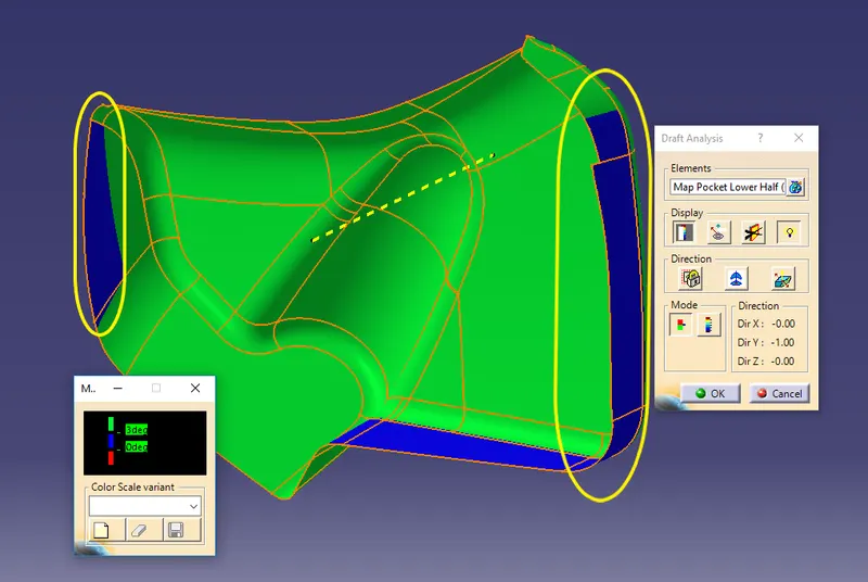
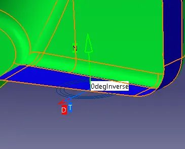
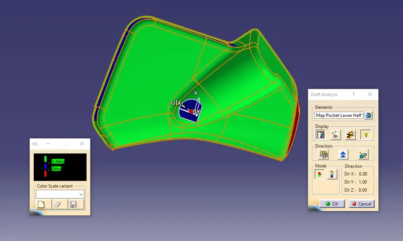
As You saw in the image there is a blue color at some sports and the running point value is showing 0deg value because those are sharp edges to clear that we have to inform to respected A_Surface Team and get the changed component and work on it.
The total A_Surface is clearing the Draft Analysis.
3 B&C_Surface Creation & Checking Draft Analysis.
Why do we create B&C_Surface?
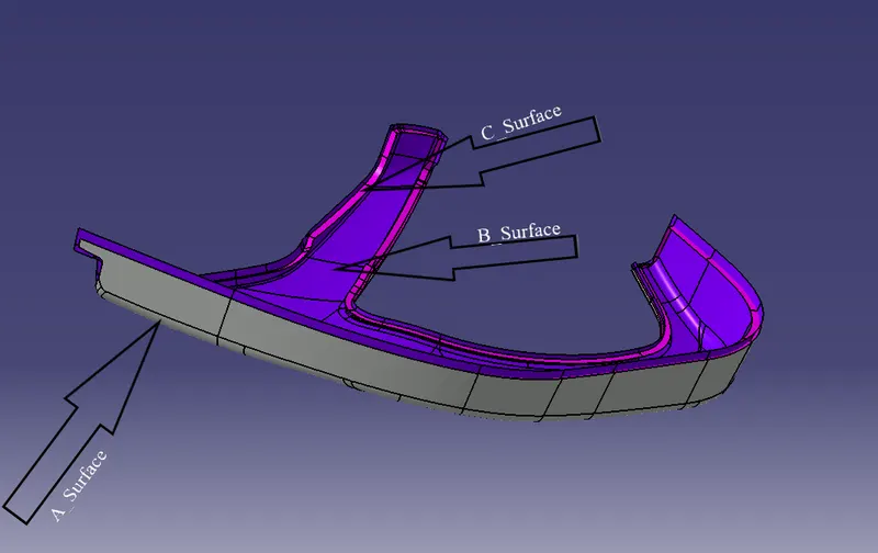
The A_Surface which we receive does not have any thickness and any design principle. It's just an imaginary sketch and we can not manufacture that component that's why we create B&C_Surface by Following all the design Principles, And it's easy to manufacture.
By using Surface workbench commands I created the B&C_Surface
Arm Rest
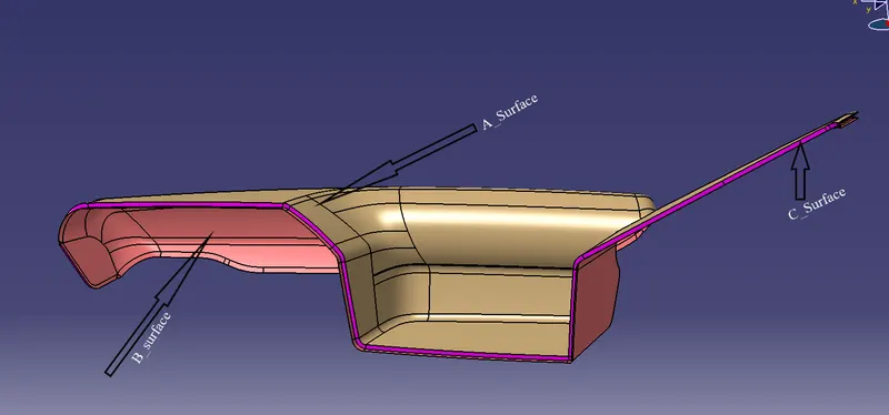
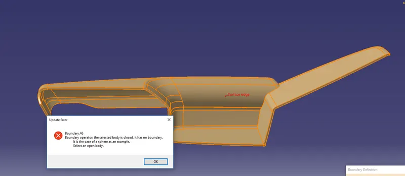
After Creating all surfaces I used the Join and Trim Commands to get the Solid body
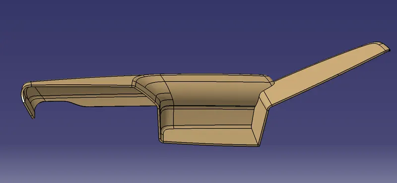
How Can we say that it's a Solid Body?
By checking the boundary for the component, if it shows any boundary then the component is not a solid body, if it doesn't show any boundary then we can say it's a solid body.
Draft analysis
Main Tooling Axis
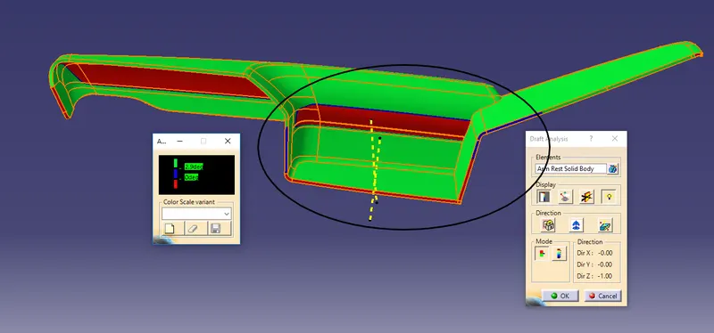
Lifter Tooling Axis
The component is ready for Manufacturing
Lower Substrate
After Creating all surfaces I used the Join and Trim Commands to get the Solid body
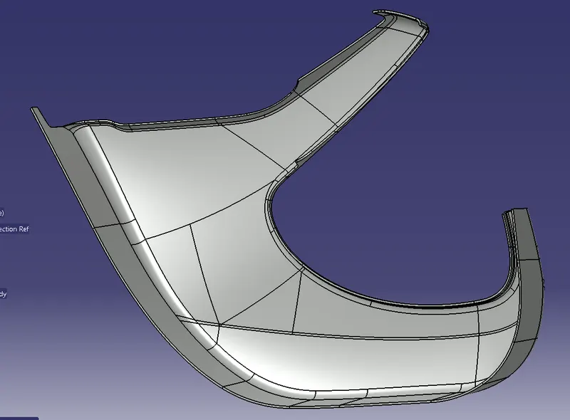
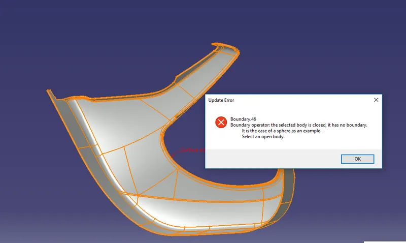
Draft analysis
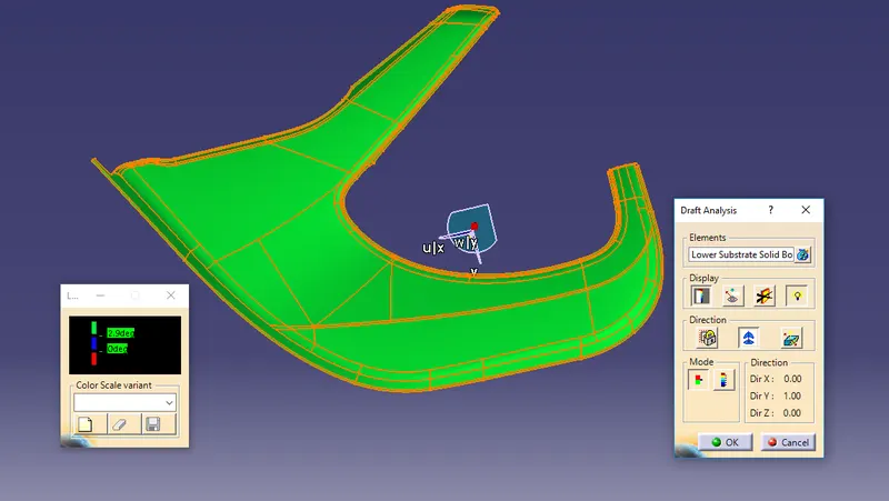
The component is ready for Manufacturing
Map Pocket
Upper Half
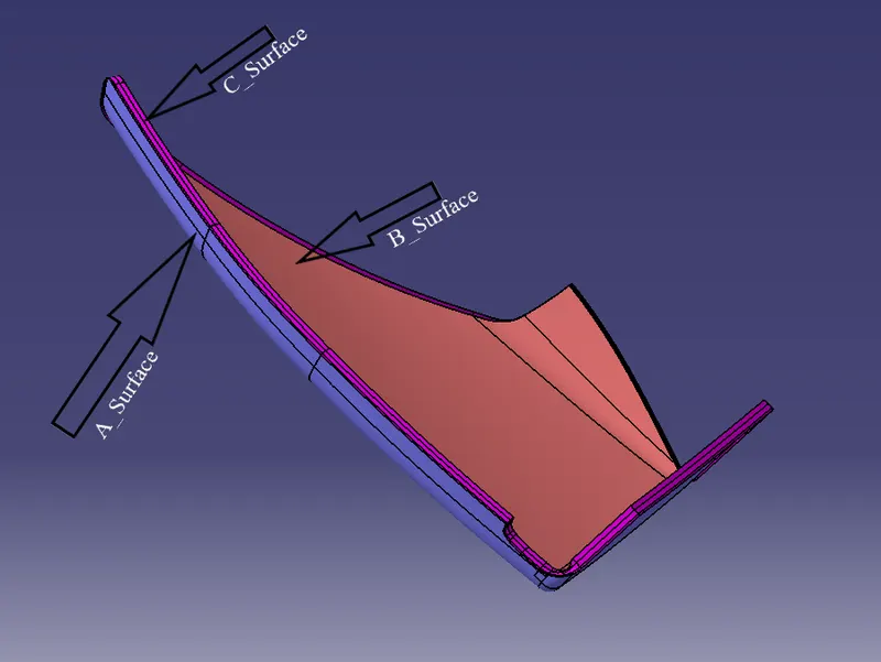
After Creating all surfaces I used the Join and Trim Commands to get the Solid body
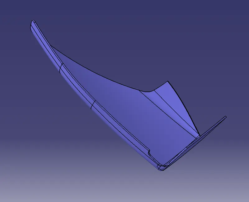
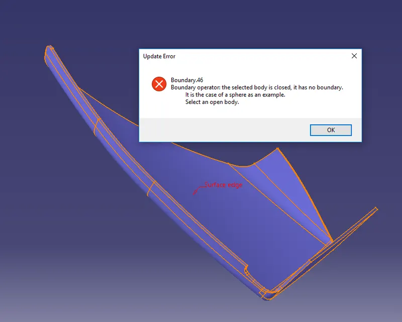
Draft Analysis
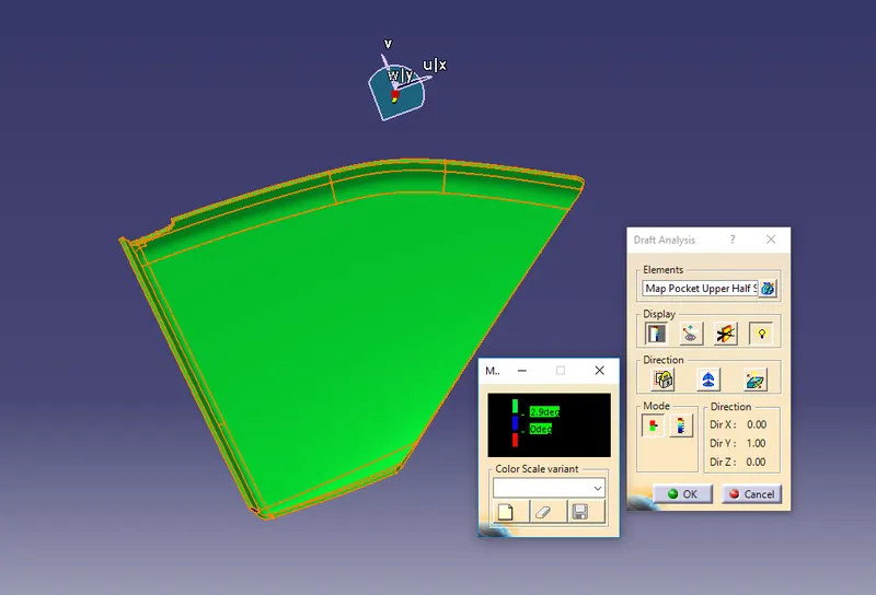
Lower Half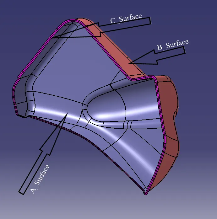
After Creating all surfaces I used the Join and Trim Commands to get the Solid body
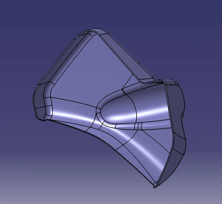
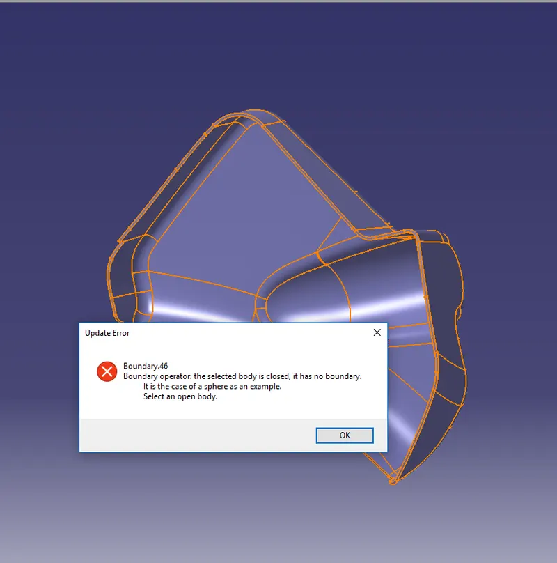
Draft Analysis
The component is ready for Manufacturing
4 B_side Features Creation (Push clip, Dog House, Heat Stake, Flanges, Screw Boss) & Checking Draft Analysis.
Why do we have to create the Features?
Features are commonly found in injection molding designs. They are used to aid in the assembly of molded parts by providing a channel between the Plastic component and Sheet metal. Some of the features are
- Ribs
- Flanges
- Heat Stakes
- Screw boss
- Dog House
- Push Clip
These features are created with the help of the master section which is given with the A_Surface
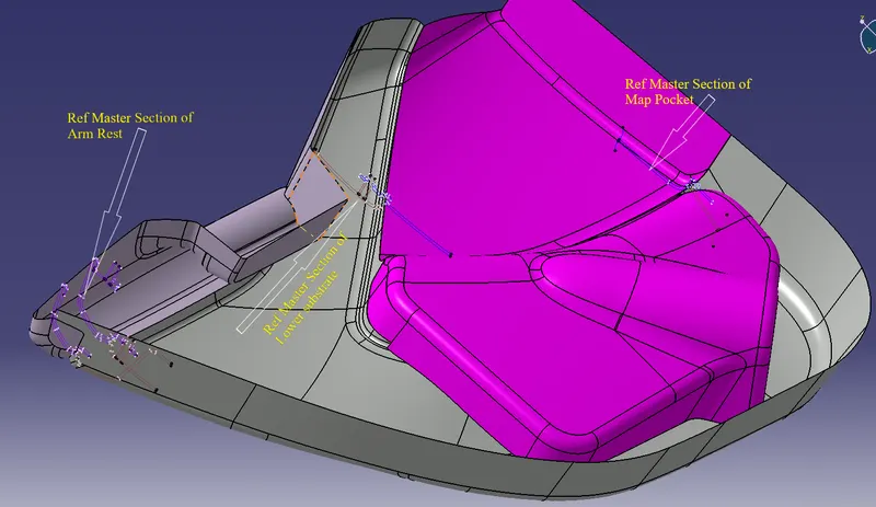
The Ref Master Section says that this component has flanges on Arm Rest, and Map Pocket, Screw Boss on Arm Rest, Dog House Push clip-on Lower Substrate and Map Pocket, Heat Stakes on Lower Substrate And Map Pocket.
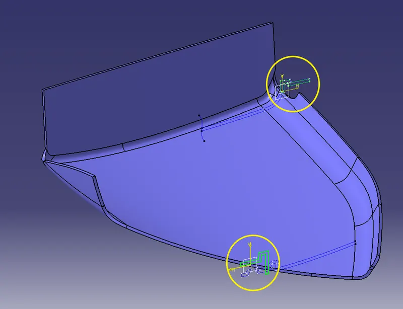
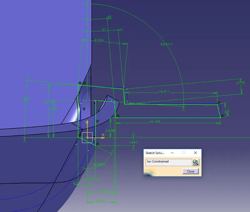
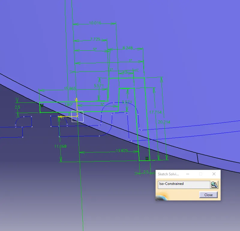
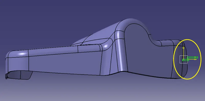
Flanges Creating on Map Pocket
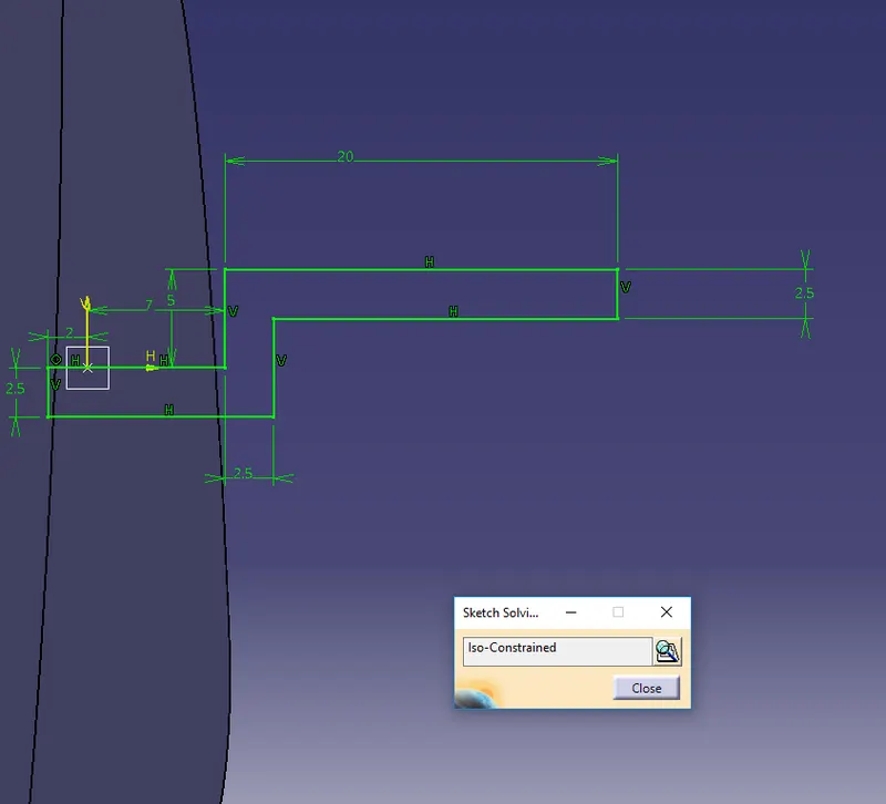
Flanges Creating on Arm Rest
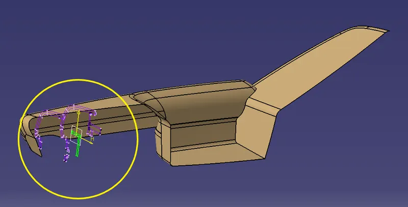
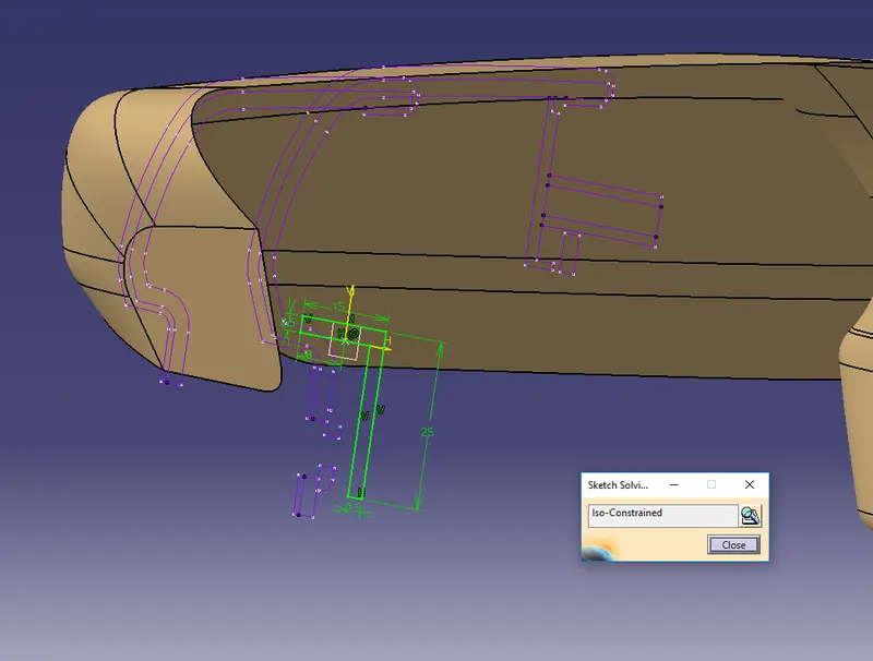
By Using Solid Workbench commands (Pad) I make the sketches in solid body
Copy the solid body and paste with paste special->AS Result with the link I created multiple flanges wherever required and position them with Translation and revolve command.
Map Pocket
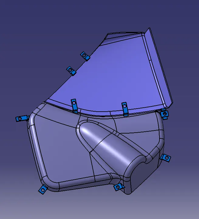
Arm Rest
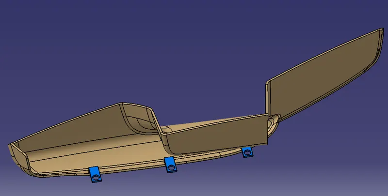
Draft Analysis
Map Pocket with Flange
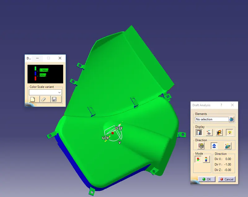
Arm Rest With Flange
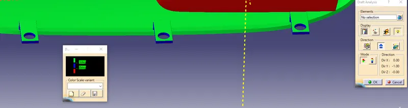
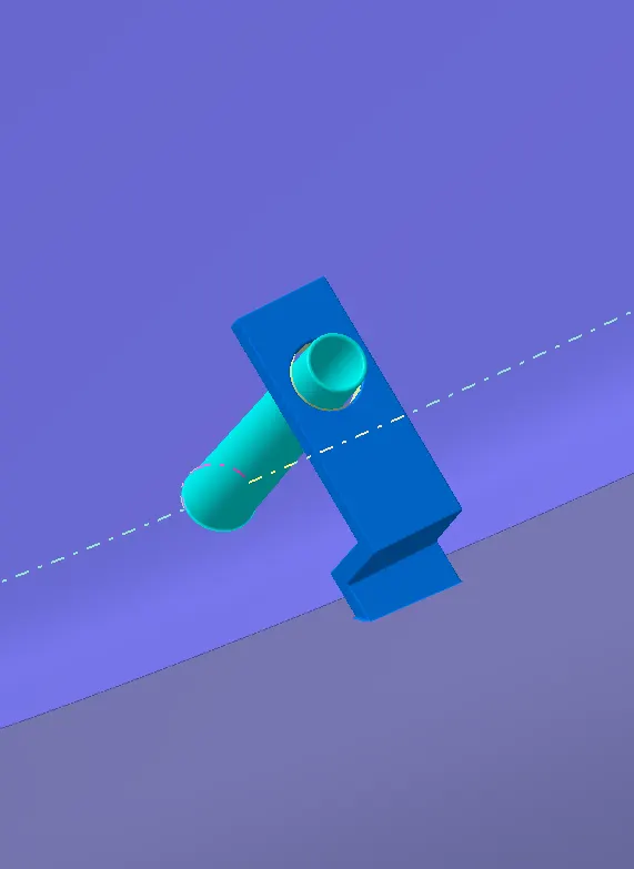
Heat Stakes on Map Pocket
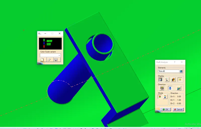
By using the Extract command I created the Ref size of the heat stake from the flanges and extruded it till the surface passed and thickens the surface.
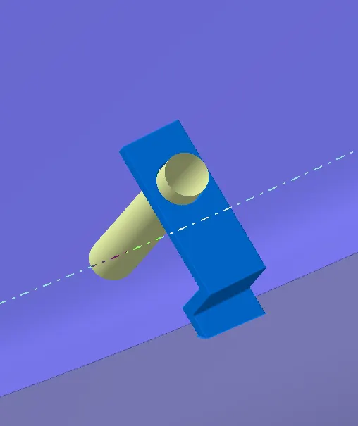
Draft Analysis
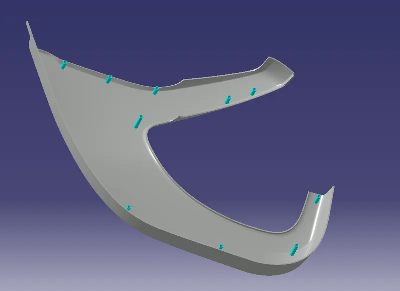
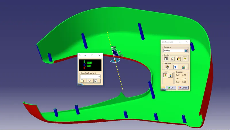
In the same manner for the lower substrate also
Draft Analysis
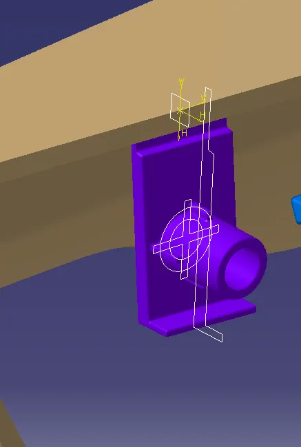
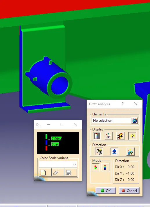
Screw Boss Creation on Arm Rest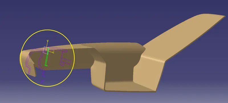
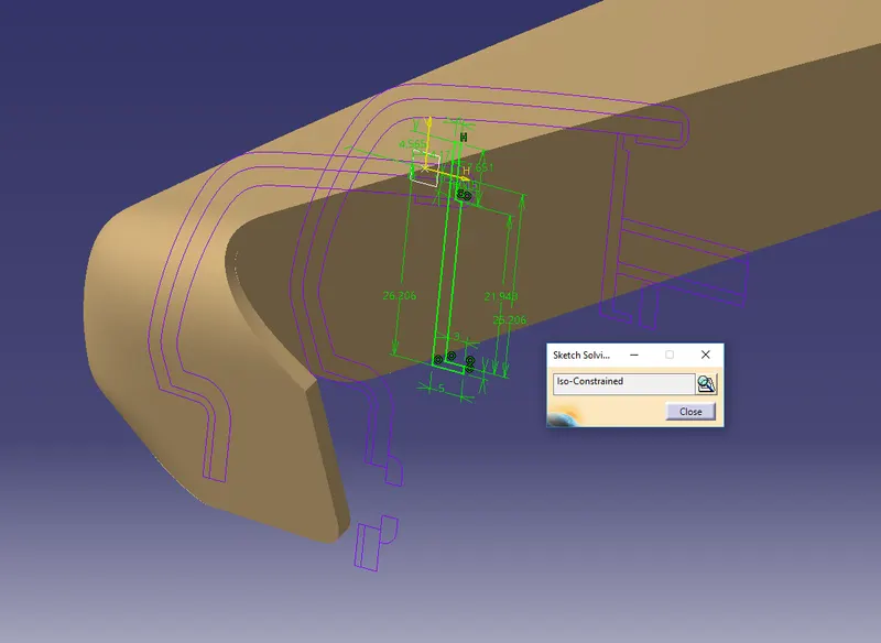
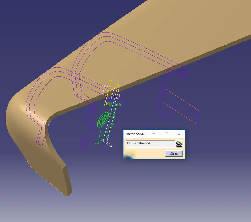
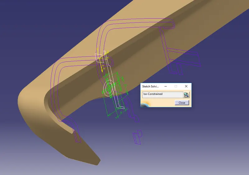
Draft Analysis
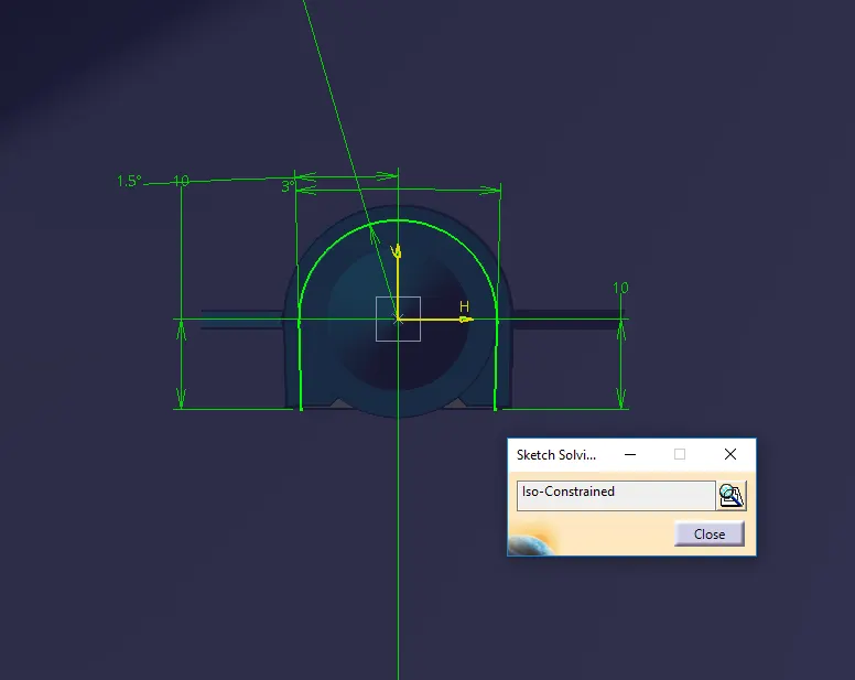
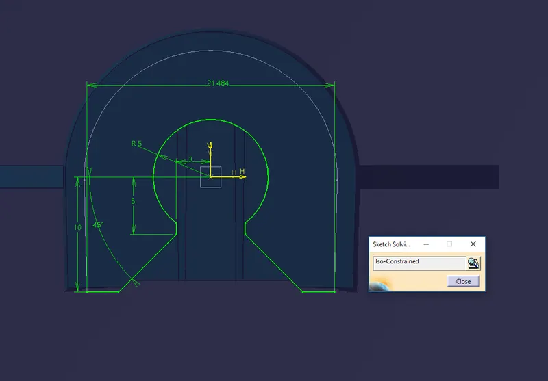
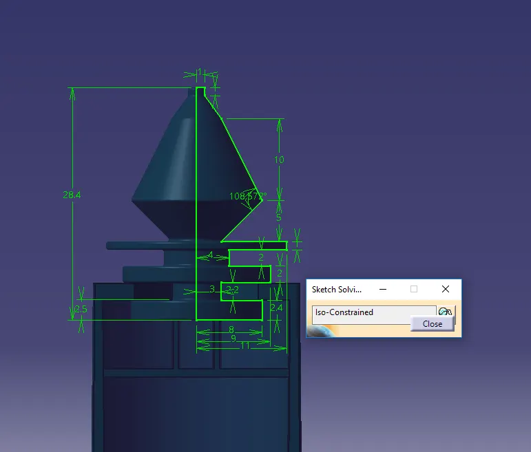
Dog House And Push Clip Creation on Lower Substrate
Draft Analysis
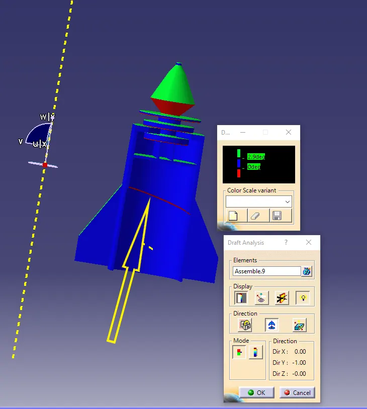
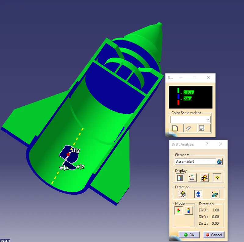
Total Draft Analysis of the Components with the Features
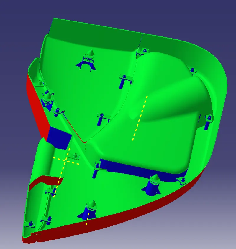
The part is ready for manufacturing
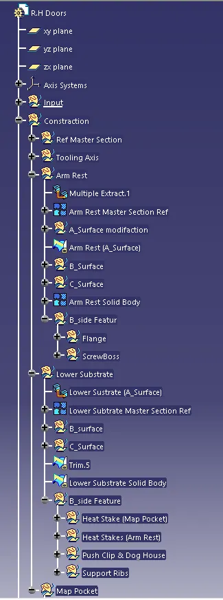
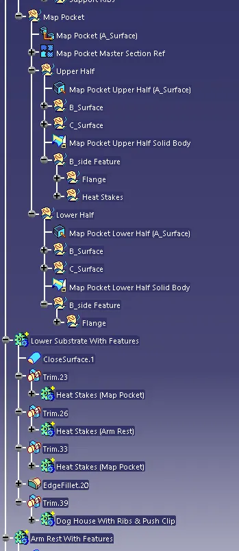
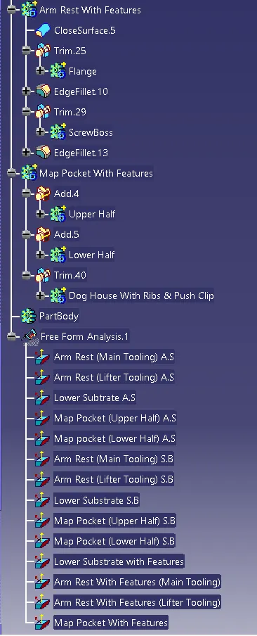
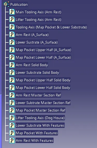
Tree Structure