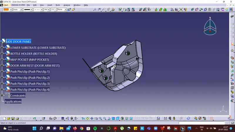
Week 11 - Final project
1. LOWER SUBSTRATE
A) TOOLING AXIS CREATION
X axis tooling direction analysis - It can be seen that extra side core is required to clear the part hence the x axis based tooling cannot is not considered.
Y axis tooling direction analysis - It can be seen that all portion of the part is cleared through this tooling direction and hence the y axis is considered for tooling. Further, the master section is used to create tooling axis along y axis.
Z axis tooling direction analysis - It can be seen that top hole remains and may require additional tooling to clear hence the z axis based tooling is not considered.
TOOLING AXIS CREATION ALONG Y DIRECTION
Step 1: Master section for lower substrate is consider as reference to create tooling axis along y direction as show in below figure.

Step 2: A line and two points are extracted from master section for tooling axis creation using extract tool. The extracted line and points are shown in below figure.
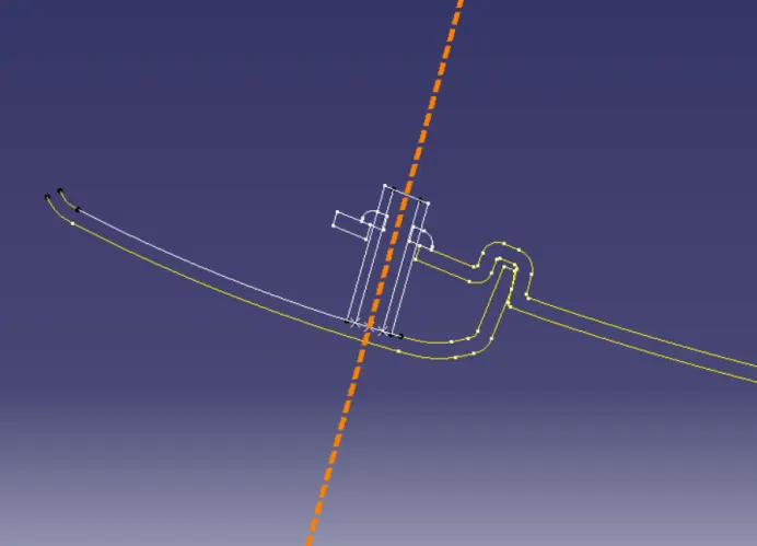
TOOLING AXIS
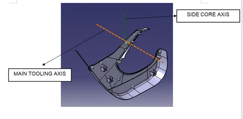
Step 3 : The tooling axis is created by selecting the point command and selecting point type as between wherein earlier extracted points are selected as reference. Further, the line command is selected and the y axis is given as direction and the point created is given as reference. The tooling axis along y axis is achieved which is represented in orange dotted line in above figure.
B) DRAFT ANALYSIS
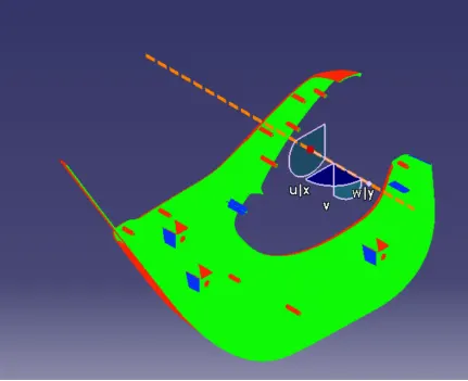
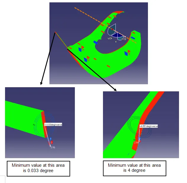
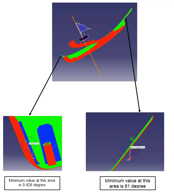
All areas are with minimum draft of 3 degrees expect the areas shown in the below images.
a) CLASS A
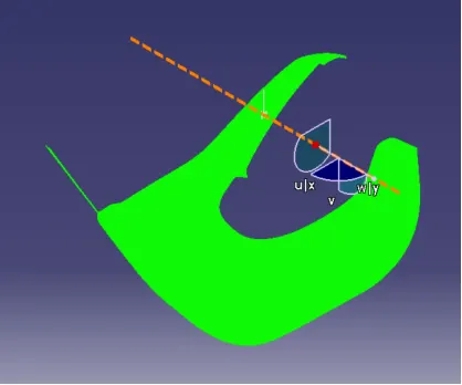
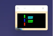
All region of the class A were cleared with minimum draft of 3 degrees.
b) CLASS B
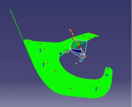
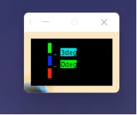
All region of the class B were cleared with minimum draft of 3 degrees.
c) CLASS C
d) DOG HOUSE WITH PUSH PIN HOLE IN MAIN TOOLING AXIS
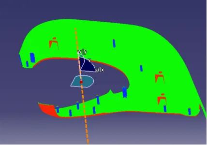
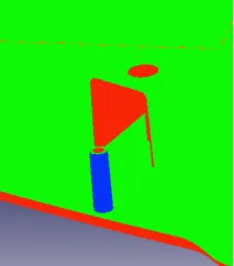
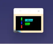
Minimum value of 1.48 degrees for outer faces of dog house.
e) DOG HOUSE WITH PUSH PIN HOLE IN SIDE CORE AXIS
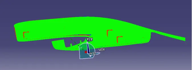
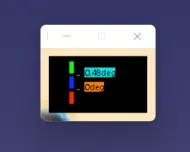
Minimum value of 0.48 degree for the inner faces of dog house.
f) FOUR WAY LOCATOR
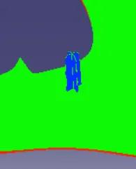
Minimum value of 1.48 degree.
g) TWO WAY LOCATOR
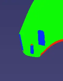
Minimum value of 1.48 degree.
TOOLING AXIS DETAILS
C) ENGINEERING FEATURES
a) HEAT STAKES
Step 1: A sketch for allocating the heat stakes was created wherein the flange circumference was taken as reference using project geometry and point was sketched at midpoint of projected geometry.
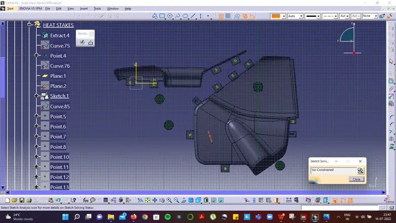
Step 2: The above sketch was used to create refernce for 3d point. After 3d point were created for individual heat stakes, a plane was selcted and point as reference for sketching heat stake (as shown in below pic). The respective diameter and length was taken from master section. Hence the sketch for heat stake is achieved.
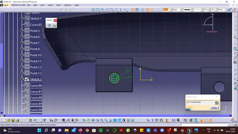
Step 3 : The sketch was extruded using pad command and insert in new body. the draft was also given. The respective heat stakes were created using copy and paste special (as result). Further each heat stakes were translated to specific point which were created earlier.
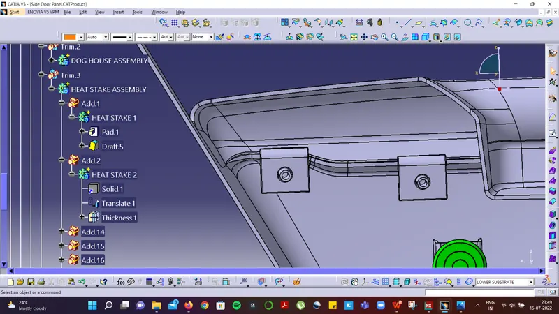
Step 4 : A Heat stake assembly was created and union trimmed with main body.
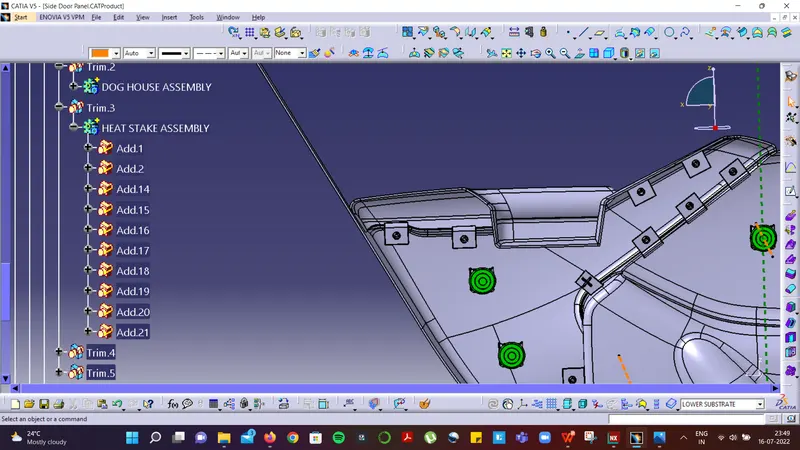
b) DOG HOUSE
Step 1: The respective surface was extracted to allocate the dog house. Further, using point command the individual points were created for respective surface according to the position of the dog house. A plane is created through a point (as shown in pic).
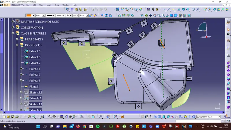
Step 2: The plane and point is selected for positioned sketch wherein the dog house sketch is created depicted in below picture.
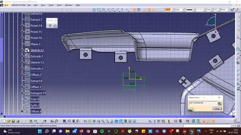
Step 3: The created sketch is extruded according to requirement.
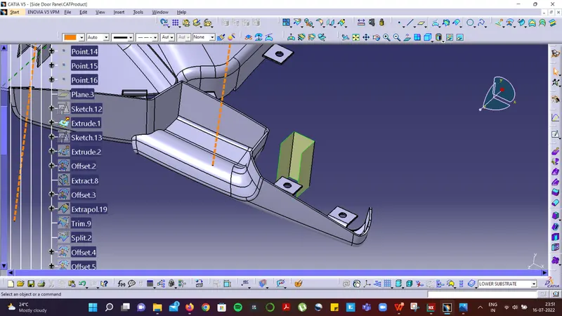
Step 4: A additional sketch was created for the roof of the dog house (as shown below).
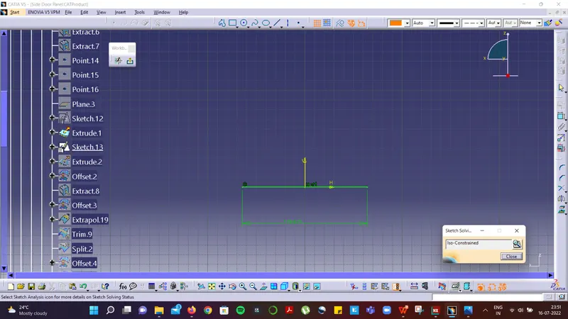
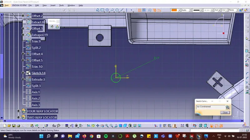
Step 5 : By using various commands such as trim, split, offest, thicken, split etc. are used to create the dog house. The dog house solid body is created and draft aslo given based on the plastic design rules. The hole for push pin is created using the split command (below the sketch for the split is shown). The individual dog house is created by copying and paste special (as result) command and translated to the points created at step 1.
c) FOUR WAY LOCATOR
Step 1: An axis system is created with respect to a point as origin. The point is created on the extracted surface (represented by yellow surface in below image).
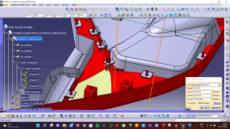
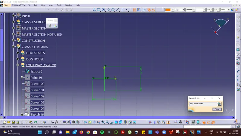
Step 2: A sketch for four way locator is drawn as shown in below image. Further, steps consists of inserting a part body and extruding the sketch with neutral axis and using applying draft angle using draft tool to respective pad faces. The chamfer and fillet are applied to the pad feature.
d) TWO WAY LOCATOR
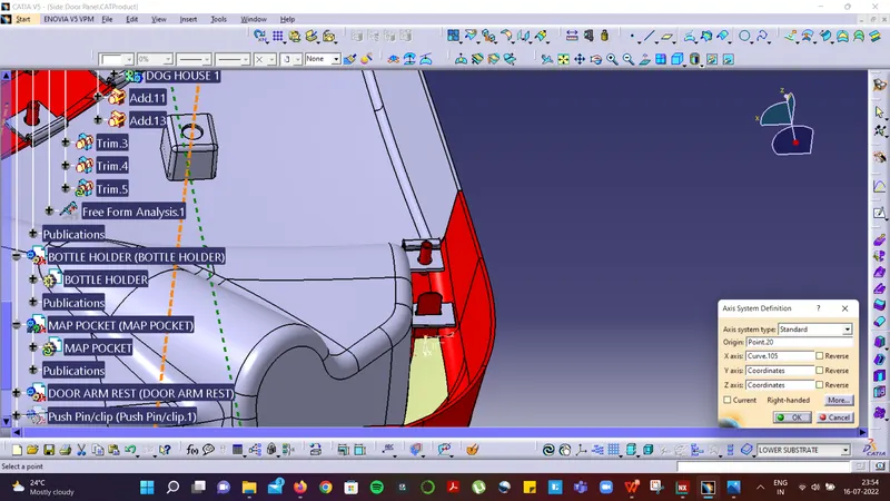
Step 1: An axis system is created with respect to a point as origin. The point is created on the extracted surface (represented by yellow surface in below image).
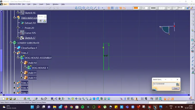
Step 2: A sketch for two way locator is drawn as shown in below image. Further, steps consists of inserting a part body and extruding the sketch with neutral axis and using applying draft angle using draft tool to respective pad faces. The chamfer and fillet are applied to the pad feature.
D) TREE STRUCTURE
2. BOTTLE HOLDER
A)TOOLING AXIS CREATION
X axis tooling direction analysis - It can be seen that extra side core is required to clear the part hence the x axis based tooling cannot is not considered.
Y axis tooling direction analysis - It can be seen that all portion of the part is cleared through this tooling direction and hence the y axis is considered for tooling.
Z axis tooling direction analysis - It can be seen that top hole remains and may require additional tooling to clear hence the z axis based tooling is not considered.
TOOLING AXIS CREATION ALONG Y DIRECTION (BISECTING METHOD)
Step 1: The intersection of the class A surface is taken with respect to xy plane denoting z axis for tool clearing axis along y axis. Further, a sketch for tooling clearing axis along y axis is created as shown in below image.
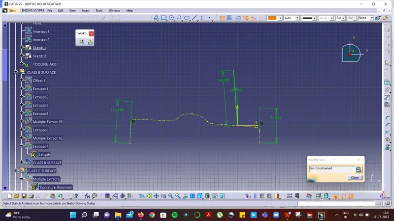
Step 2: The intersection of the class A surface is taken with respect to zy plane denoting x axis for tool clearing axis along y axis. Further, a sketch for tooling clearing axis along y axis is created as shown in below image.
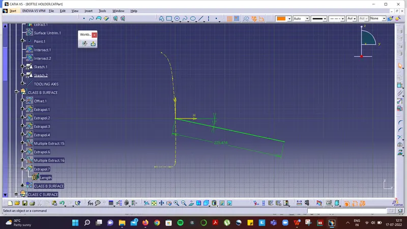
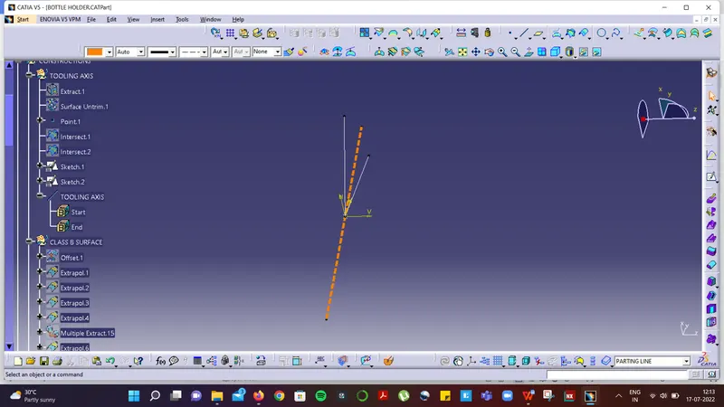
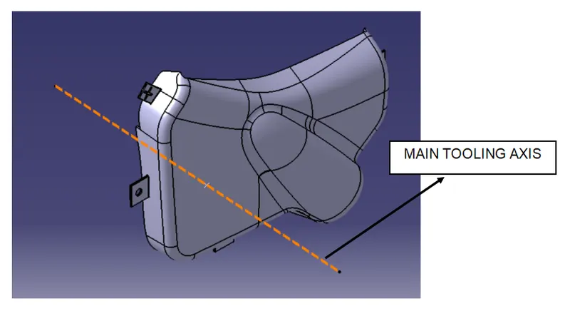
Step 3: The line command (bisecting option is selected) is used and the two axis are bisected through a point. Thus tooling axis is achieved shown as orange dotted in below figure.
B) DRAFT ANALYSIS
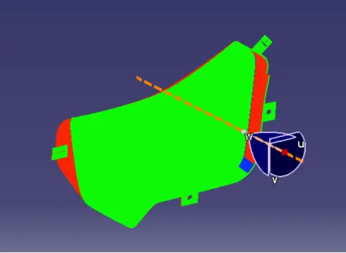
All areas are with minimum draft of 3 degrees expect the areas shown in the below images.
a) CLASS A
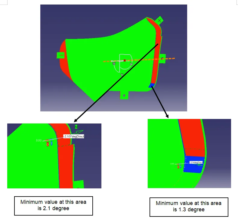
b) CLASS B
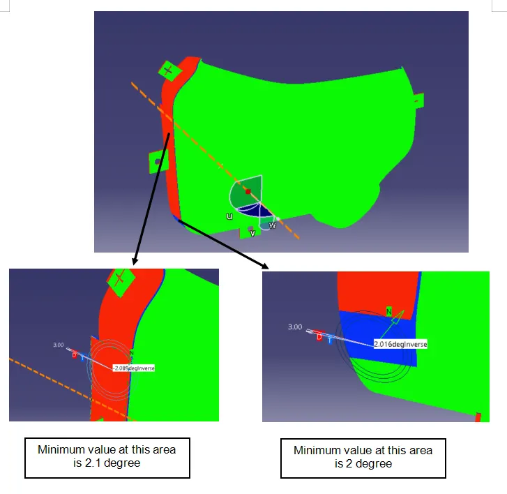
c) CLASS C
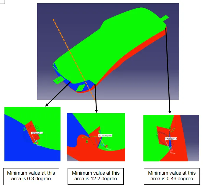
TOOLING AXIS DETAILS
C) ENGINEERING FEATURES
a) MOUNTING SUPPORTS
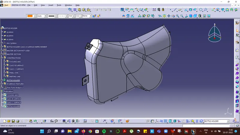
Step 1: The following surfaces from faces of the 3d model were extracted in which the mounting supports were to be sketched. The points was assigned to each extracted for accurate placement of the mounting support. A cruve was extracted from surface edge as shown below.
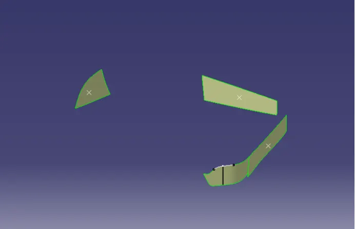
Step 2: Points were created along the extracted cruve. Further, the extracted cruve was translated to a particular distance using parallel cruve. A point was created on the parallel cruve. A vertical line was created to define an axis system for sketching mounting supports.
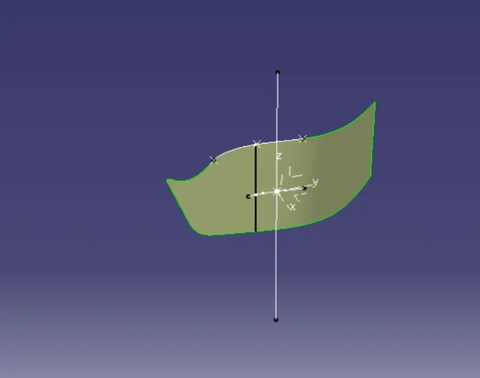
Step 3: The plane from the axis system was used to create a sketch and futher converted into solid using thick command which depicted in the following below images.
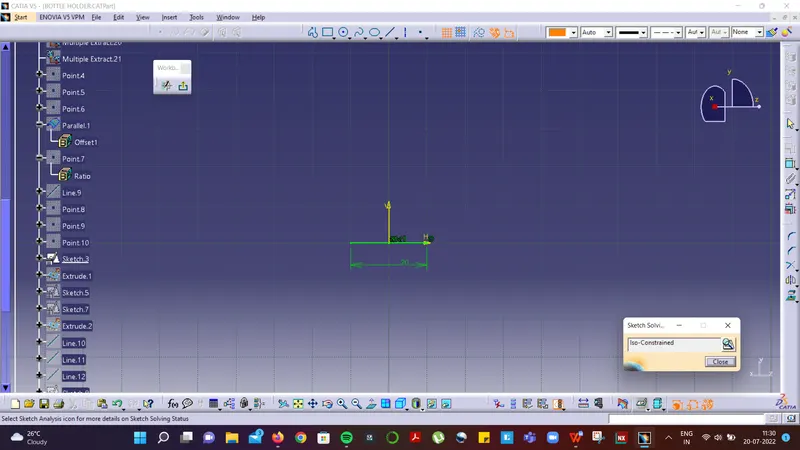
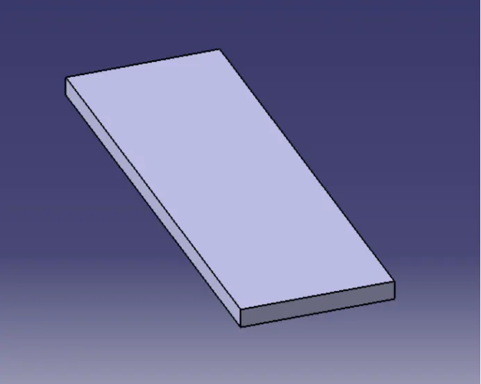
Step 4: Further, the mounting supports were translated and roatated to accordingly based on their positions. The mounting supports consisting of different slots were made projecting elements from refernece 3d and 2d sketchs. Further, commands like union trim, remove, split etc. were used to achieve the part. The below images with tree structure shows the operations performed to achieve solid body.
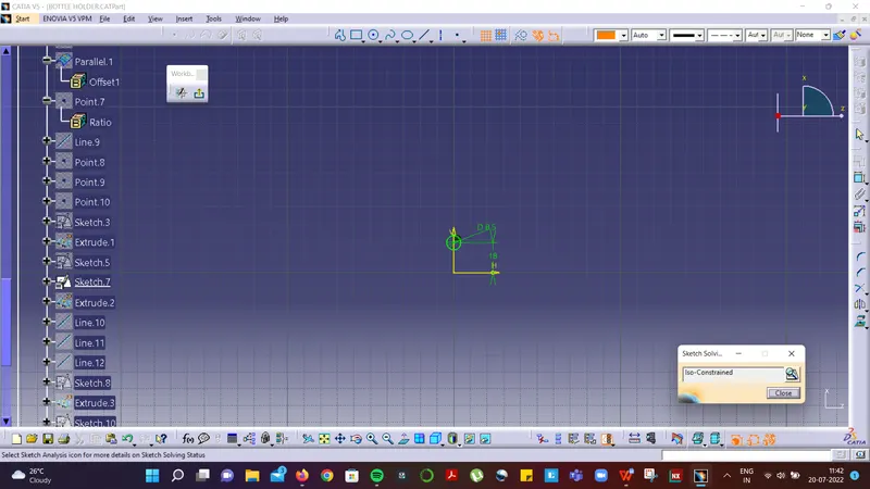
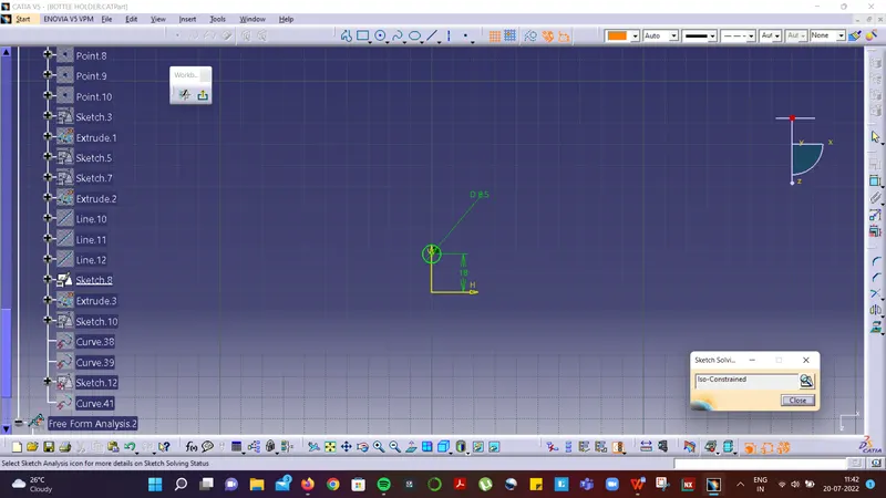
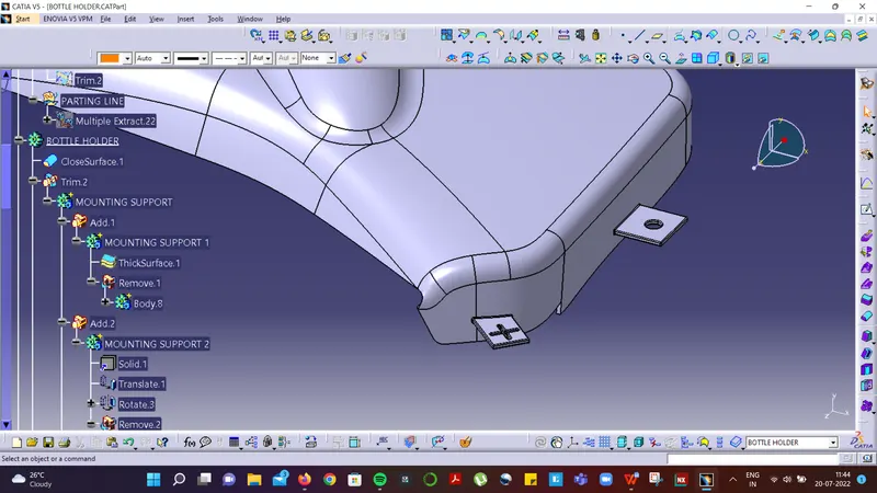
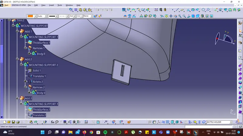
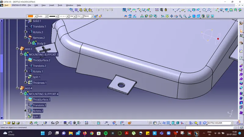
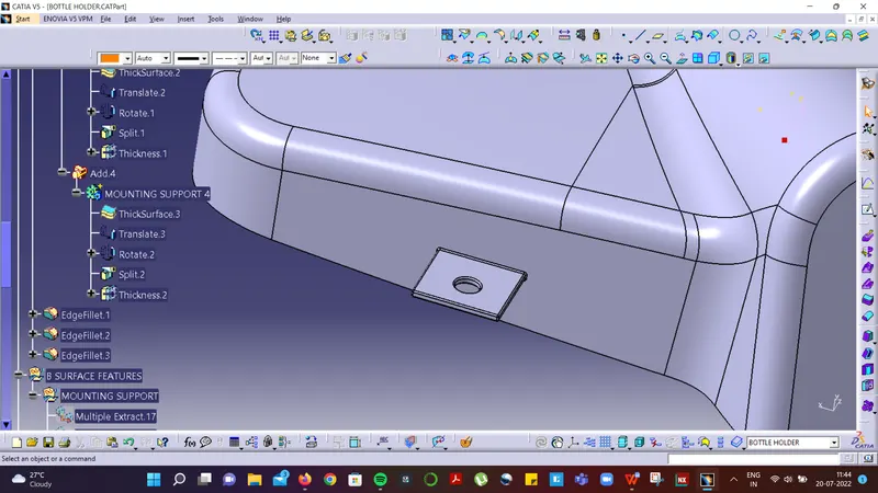
D) TREE STRUCTURE
3. MAP POCKET
A) TOOLING AXIS CREATION
X axis tooling direction analysis - It can be seen that extra side core is required to clear the part hence the x axis based tooling cannot is not considered.
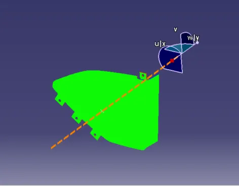
Y axis tooling direction analysis - It can be seen that all portion of the part is cleared through this tooling direction and hence the y axis is considered for tooling.
Z axis tooling direction analysis - It can be seen that top hole remains and may require additional tooling to clear hence the z axis based tooling is not considered.
TOOLING AXIS CREATION ALONG Y DIRECTION
Step 1: A surface is extracted from given Class A surface.
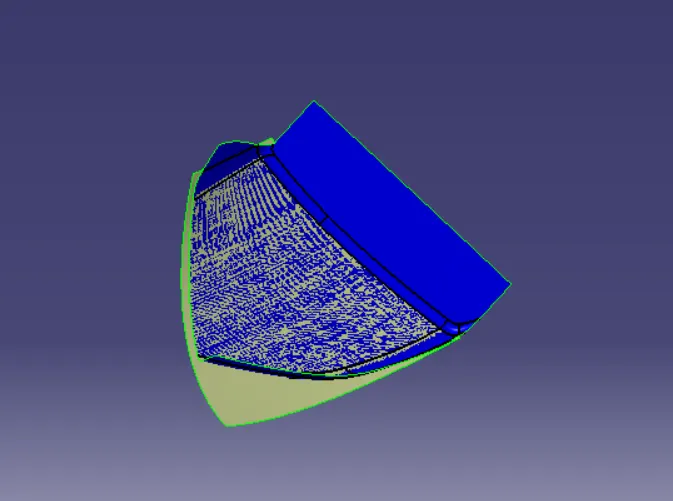
Step 2: A point is created on the extracted surface.
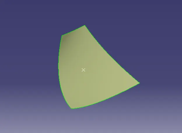
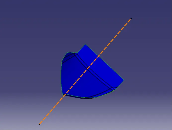
Step 3: The line command is used and point and direction is selected for creating the tooling direction. The direction is given as y direction.Hence tooling axis is achieved (represented as orange dotted line).
B) DRAFT ANALYSIS
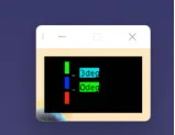
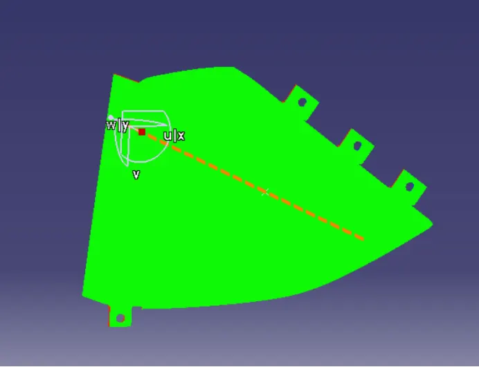
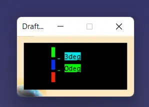
All areas are with minimum draft of 3 degrees expect the areas shown in the below images.
a) CLASS A
b) CLASS B
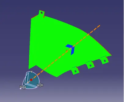
c) CLASS C
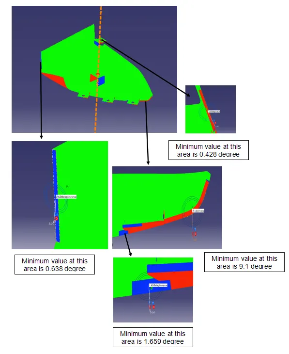
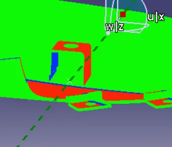
d) DOG HOUSE WITH PUSH PIN HOLE IN MAIN TOOLING AXIS
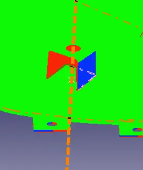
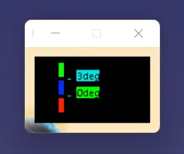
Minimum value of 1.5 degree on blue faces and 3 degree on other faces
e) DOG HOUSE WITH PUSH PIN HOLE IN SIDE CORE AXIS
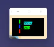
Minimum value of 0.5 degree on blue faces and 3 degree on other faces
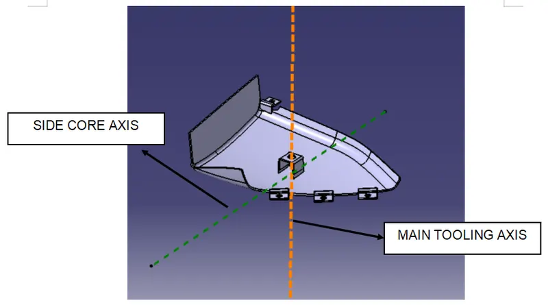
TOOLING AXIS DETAILS
C) ENGINEERING FEATURES
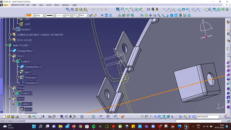
a) ARM REST CONNECTING FLANGES
Step 1: A sketch of the flange were prepared by extracting respective line from master section. The plane and point for sketch were taken from the master section.
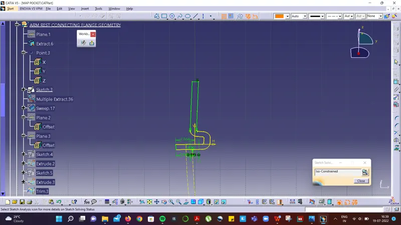
Step 2: The sketched profile was sweeped with respect to extracted line from the class B surface. Further, two surface were by creating line as shown in below images. The two extruded surface profile were offset from each other and using trim command the following closed surface profile was obtained.
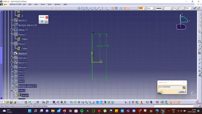
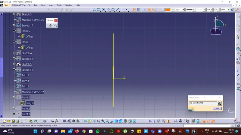
Step 3: The closed profile is shown in below image. By using close surface a solid body was obtained. A circluar sketch is drawn and extruded circular surface was created. Then using split command a hole was created in the solid body. Further, the solidbody was translated to respective points. The other flanges were created using copy and paste special (as result) and translation commands.
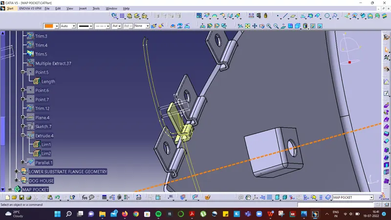
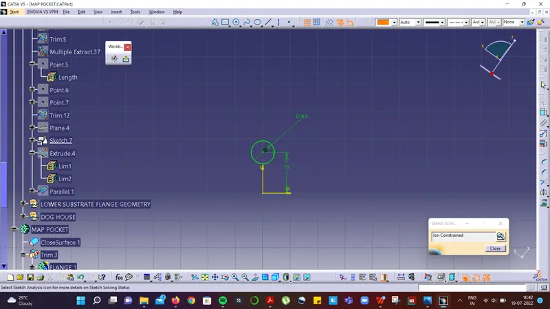
b) LOWER SUBSTRATE FLANGE
Step 1: A profile sketch was created by projecting the master section as shown below.
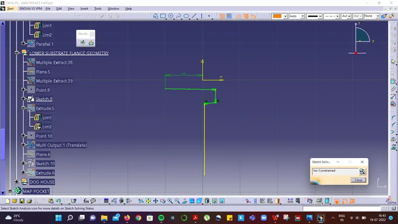
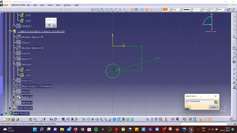
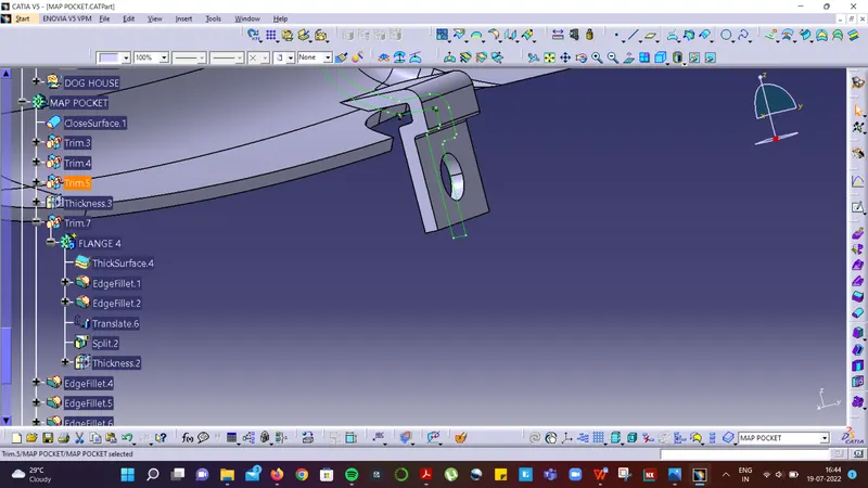
Step 2: The sketch was converted into solid body using thick surface tool and using split command a hole was created.
c) DOG HOUSE
Step 1: The dog house gemoterical set and part body was copied and pasted from the Lower substrate using copy and paste special command. Further, using union trim the dog house was added to main part body.
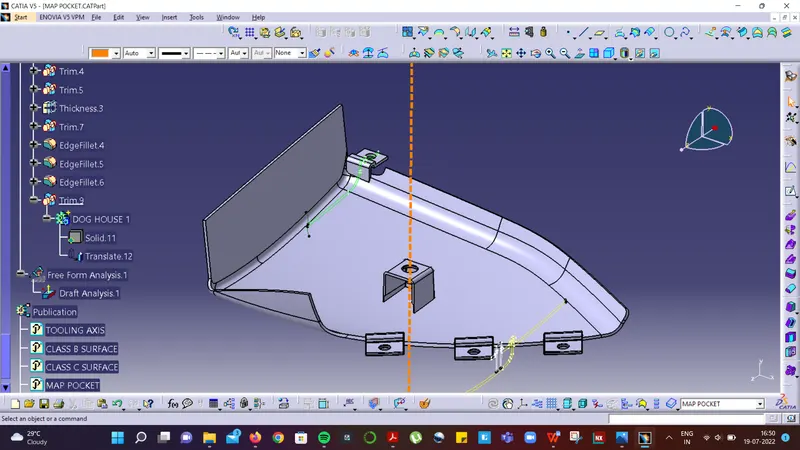
D) TREE STRUCTURE
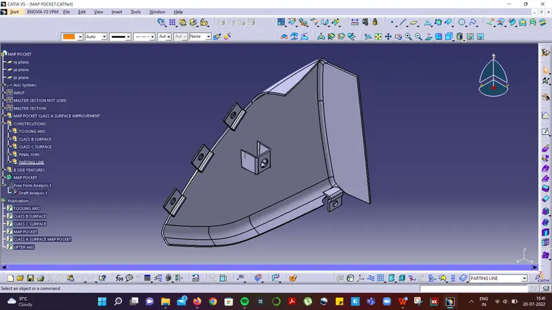
4. DOOR ARM REST
A) TOOLING AXIS CREATION
X axis tooling direction analysis - It can be seen that extra side core is required to clear the part hence the x axis based tooling cannot is not considered.
Y axis tooling direction analysis - It can be seen that top hole remains and may require additional tooling to clear hence the y axis based tooling is not considered.
Z axis tooling direction analysis -
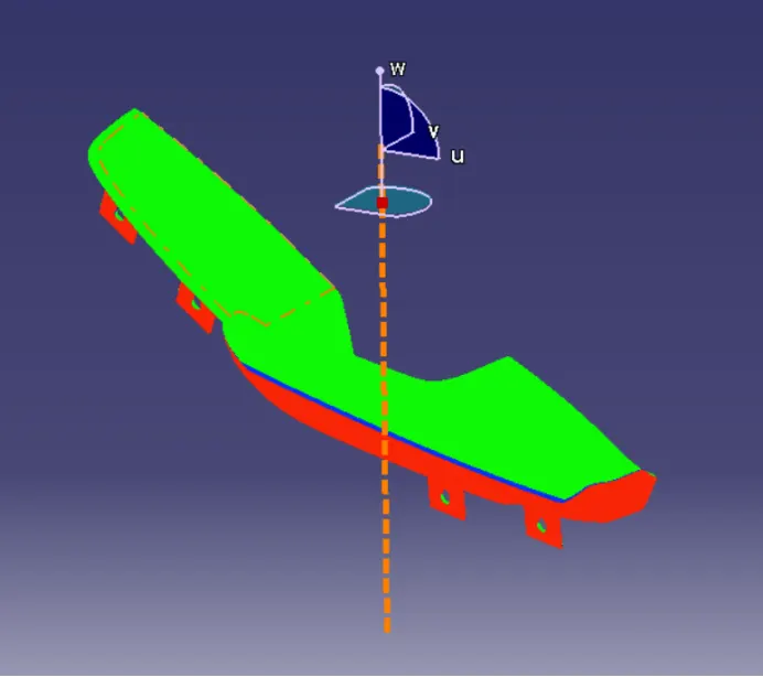
It can be seen that all portion of the part is cleared through this tooling direction and hence the z axis is considered for tooling.
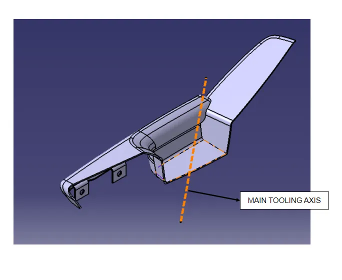
TOOLING AXIS CREATION ALONG Z DIRECTION (BISECTING METHOD)
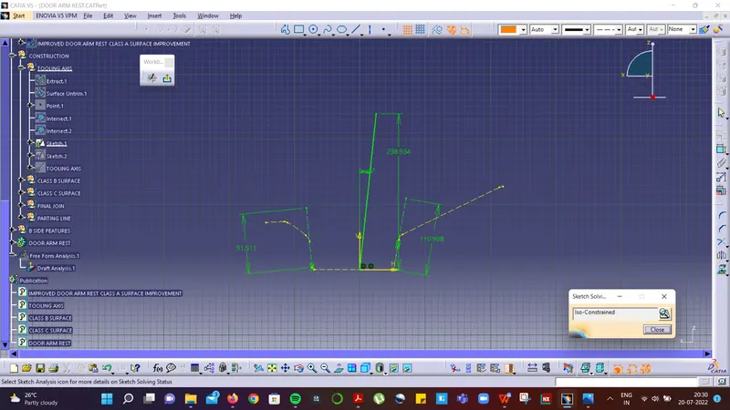
Step 1: A surface was extracted from class A surface and a point was created on the surface. The intersection of the class A surface is taken with respect to xz plane denoting y axis for tool clearing axis along z axis. Further, a sketch for tooling clearing axis along y axis is created as shown in below image.
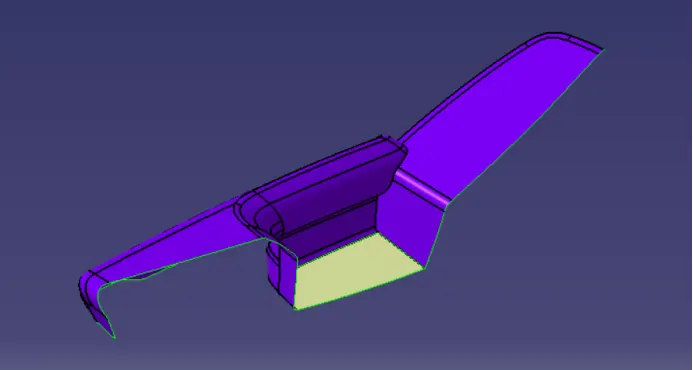
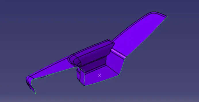
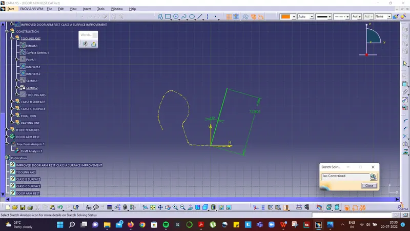
Step 2: The intersection of the class A surface is taken with respect to yz plane denoting x axis for tool clearing axis along z axis. Further, a sketch for tooling clearing axis along y axis is created as shown in below image.
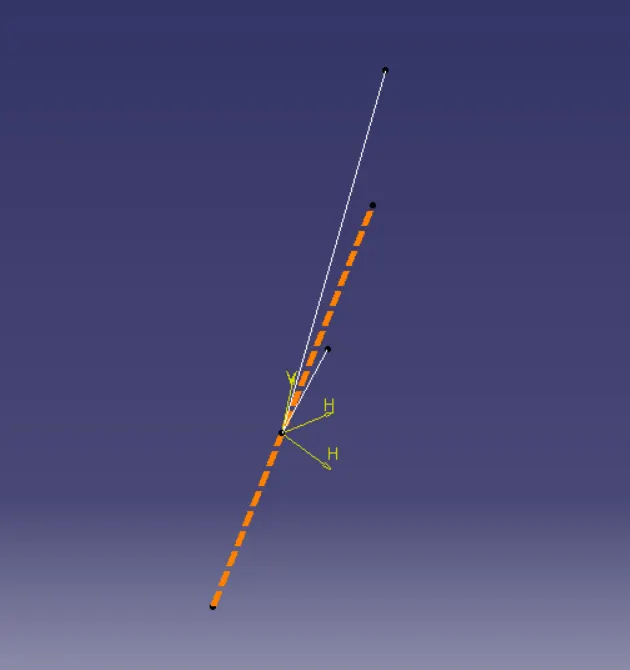
Step 3: The line command (bisecting option is selected) is used and the two axis are bisected through a point. Thus tooling axis is achieved shown as orange dotted in below figure.
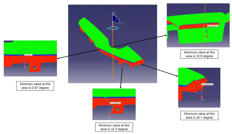
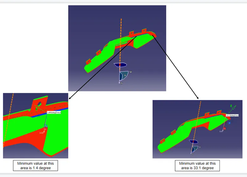
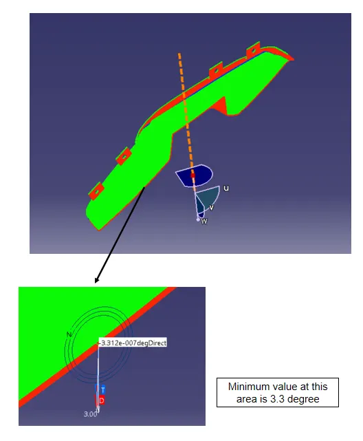
B) DRAFT ANALYSIS
All areas are with minimum draft of 3 degrees expect the areas shown in the below images.
a) CLASS A
b) CLASS B
c) CLASS C
TOOLING AXIS DETAILS
C) ENGINEERING FEATURES
a) FLANGES
Step 1: The master section was used to create the plane and point for sketch plane. The section from master section was projected for sketch.
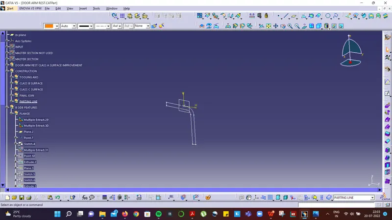
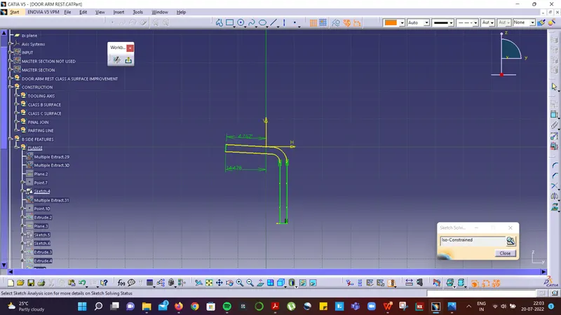
Step 2: The sketch was surface extruded to a certain distance. Other surface were created to trim the surface to particular width and obtain a closed profile. The close surface tool was used to obtain the solid body.
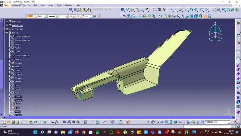
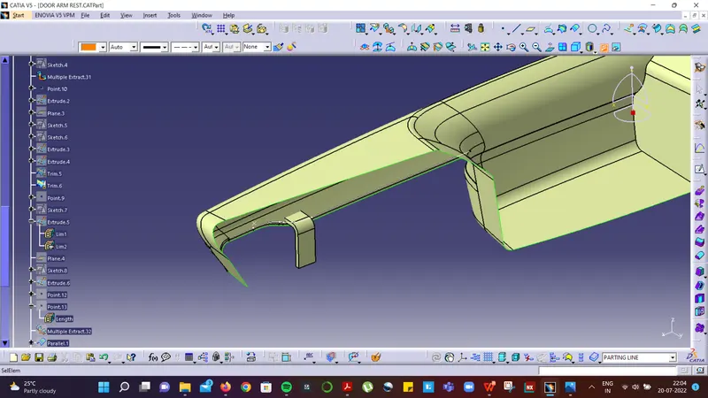
Step 3: The circular profile was drawn and then extruded. By using split command a hole was created within the solid body.
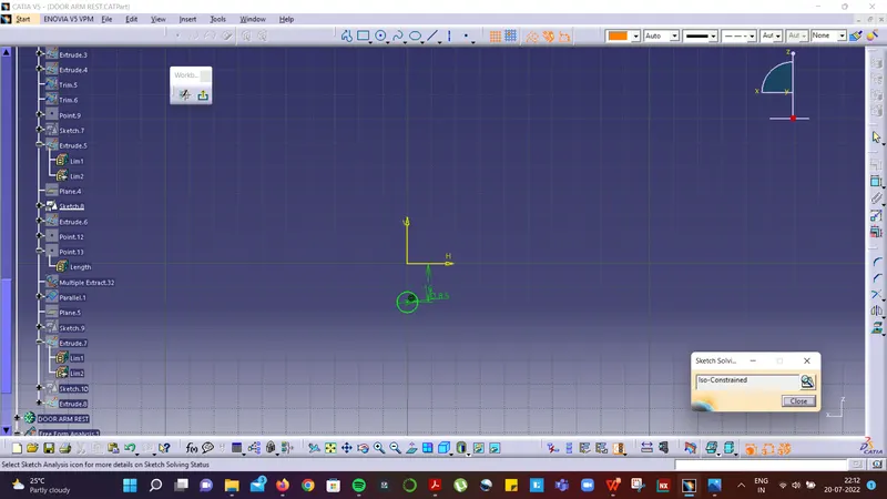
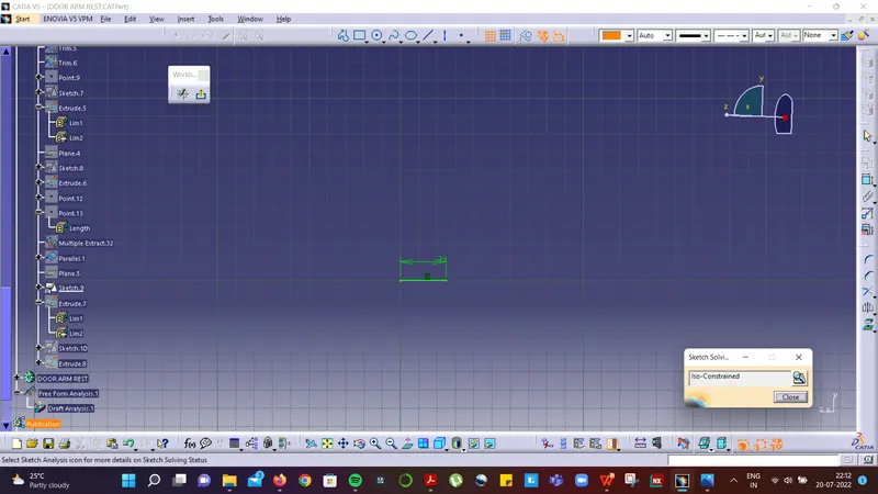
Step 4: The above steps were repeated to created another flange wherein the reference sketch was not taken from master section but instead a separate plane and point was created and a line sketch was drawn.
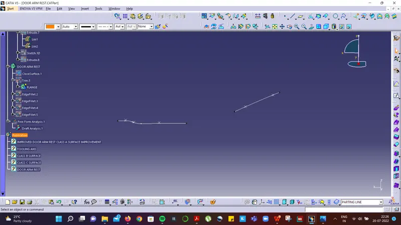
Step 5: The below image show two extracted line profiles with points for translating the flanges created. Two different profile of flanges were drawn according to profile of surface.
Step 6: The solid body of flanges obtained were translated to respective assigned point. Using boolean operation (Add) were added to common part body (Flanges). Finally, were union trimmed with main body.
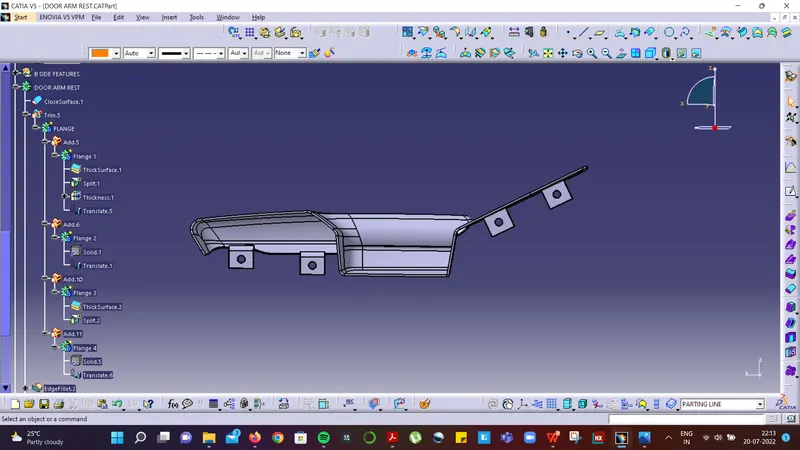
D) TREE STRUCTURE
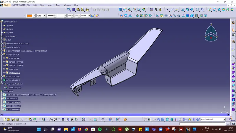
4) FINAL ASSEMBLY