Week 11 - Final project
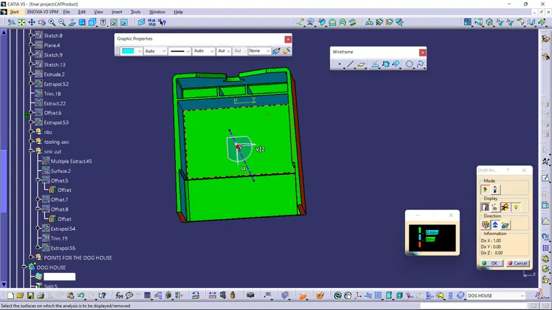
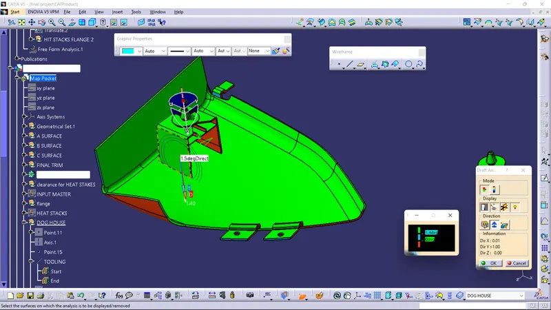
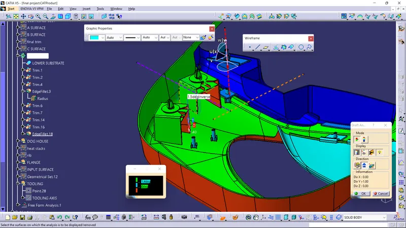
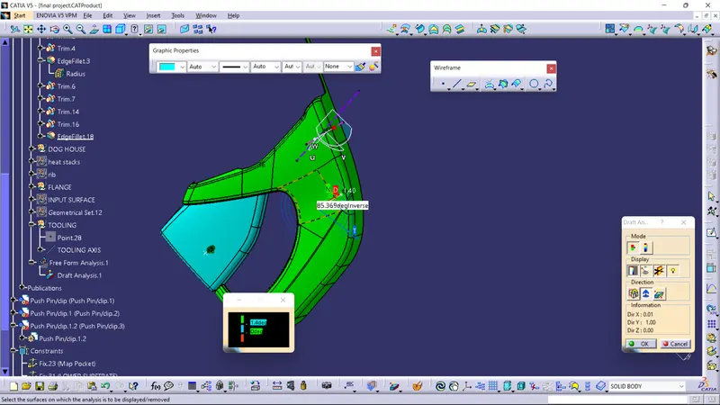
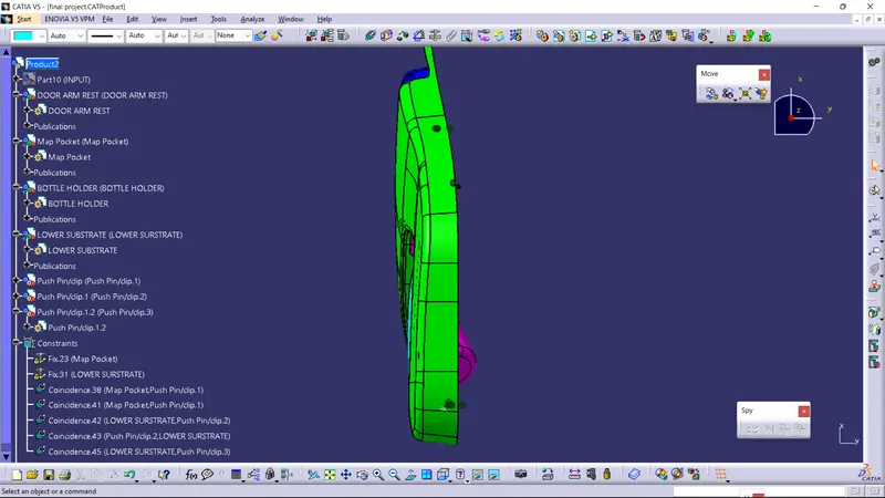
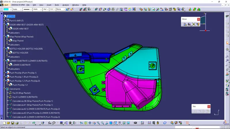
- TOOLING AXISES-First tooling axis I created for the door arm rest, showing in the below figure here I created the orange tooling axis for creation of c surface sweep the c surface. It is created with the help of 'NORMAL TO SURFACE' command.
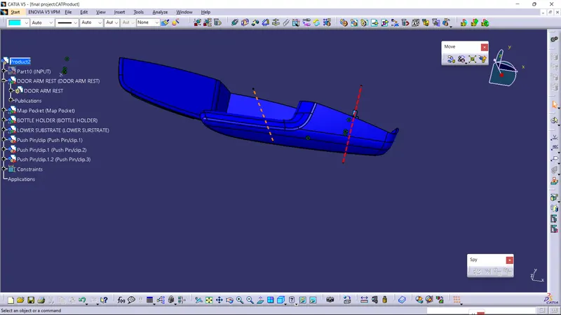 And the red one is for the Heat stakes creation.I created that in bisecting method with the help of master section.
SECOND tooling what I creted in the lower substrate for the DOG HOUSES AND THE HEAT STAKES.(Show in below)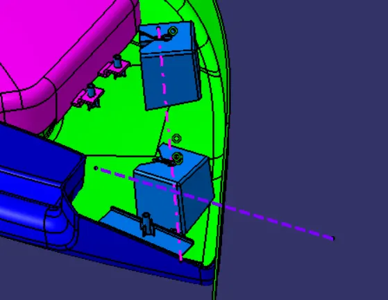 here I created the two tooling axises for the dog house and the heat stacks also.
THIRD tooling what I created in the MAP POCKET for clearation for the DOG HOUSE and the part also.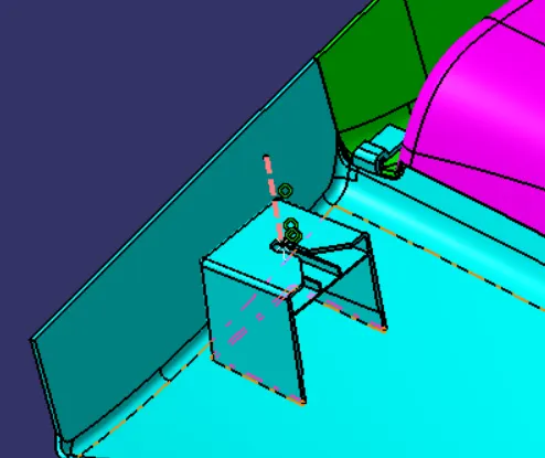 HERE I created the tooling with the help of 'normal to surface' command.
 - FLANGES-here I created flanges with the help of master section. I created the flanges in the required formation of it. I didn't use so much material for the flanges. I cut them in short parts where the HEAT STAKES rest. I gave 0.5 approximate of clearance for the HEAT STAKES.
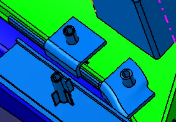
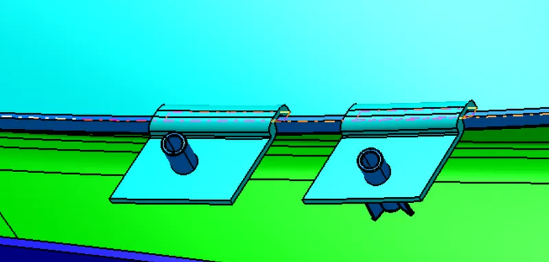
On the above image the HEAT STAKES are looked like.
AND AGAIN FOR THE CLEARANCE OF HEAT STAKES FOR ALL DIRECTIN SHOULD BE 2*D(D=Dia of the Heat Stakes), I did that.
I gave some extras with the help of master section for better cross sections(In the bellow image).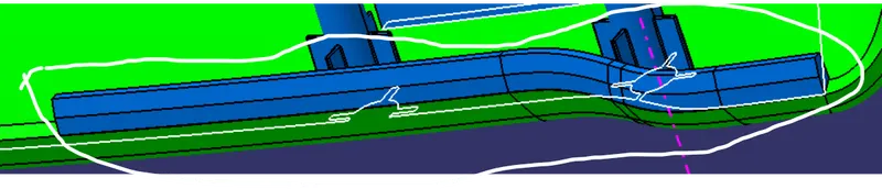
- B FEATURES- The B-features is the feature which are build on the B surface. Here the Heat stacks and Dog House both are the B features. HEAT stakes have 7.5mm outer and 4.5mm inner dia. I gave support ribs on the heat stakes. The support ribs thickness is 1mm.
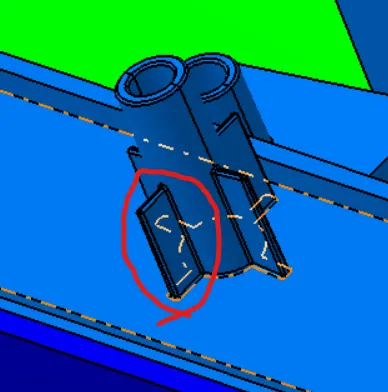
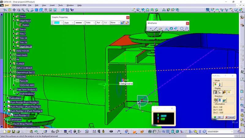
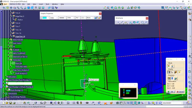
I gave 0.5 degree of draft on the outside of heat stakes, and for the outer of Dog House I gave 1.5 degree of draft and the inner side is 0.5 digree of draft.
HEAT STAKES- Heat stakes are generally used for connecting two parts by melting the heat stakes. When the high pressure is given the connecting area of Heat Stakes are melted and after cooling the parts will be connected. And the ribs are created for the strenthen of Heat Stakes.
DOG HOUSE-Dog House are used to assemble parts to each other.for the dog house I use 2mm of wall thikness. Here on the top of the dog house I created a key hole where the push pin will be pushed and then another part will be joint. Here I created ribs inside the dog house. The ribs are actually for indicating the limit of the push pin. The front side of the Ribs thickness is 1mm.
- DRAFT ANALYSIS-I have done individually the draft analysis for the parts, an for the dog house. I gave outer 1.5 degree of draft of the dog house, and 0.5 degree of draft in the inner side of dog house.
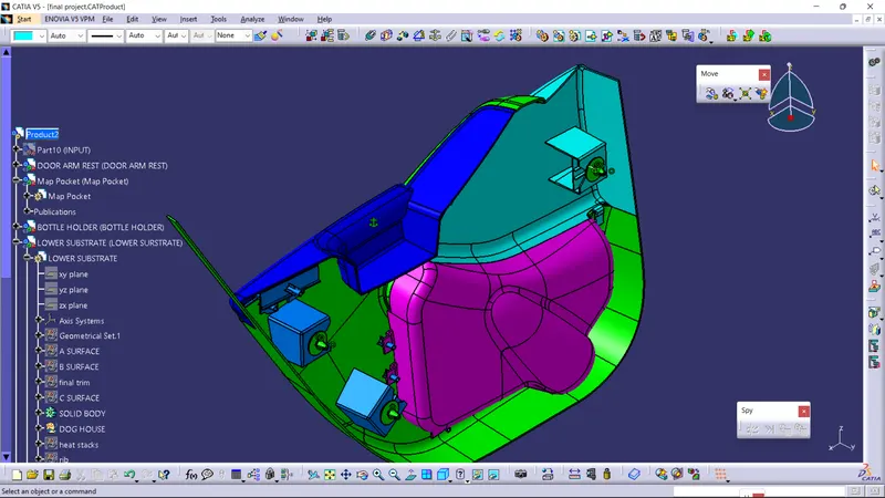
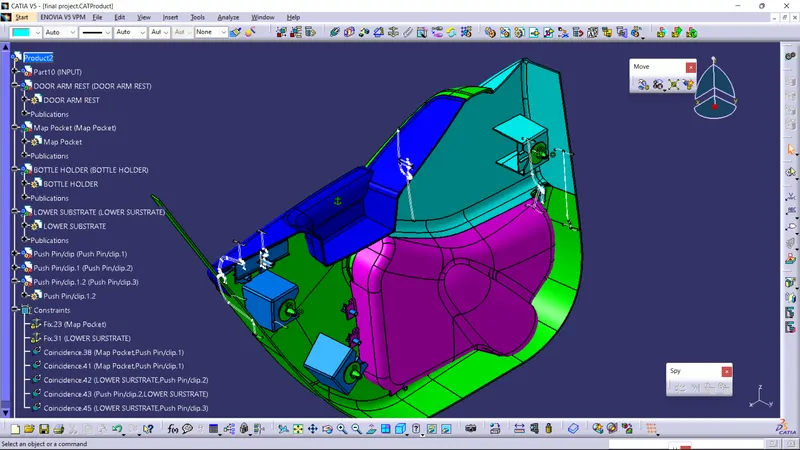
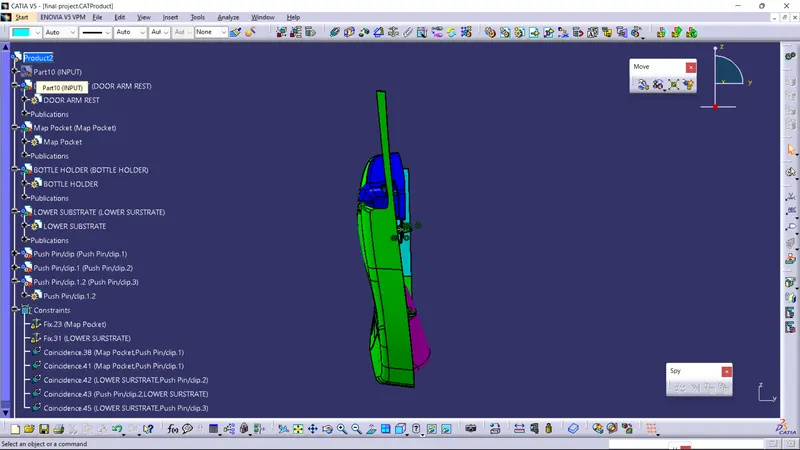
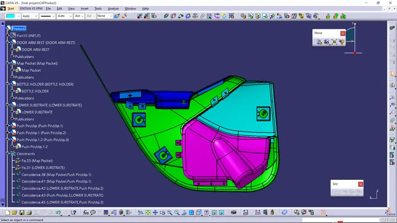
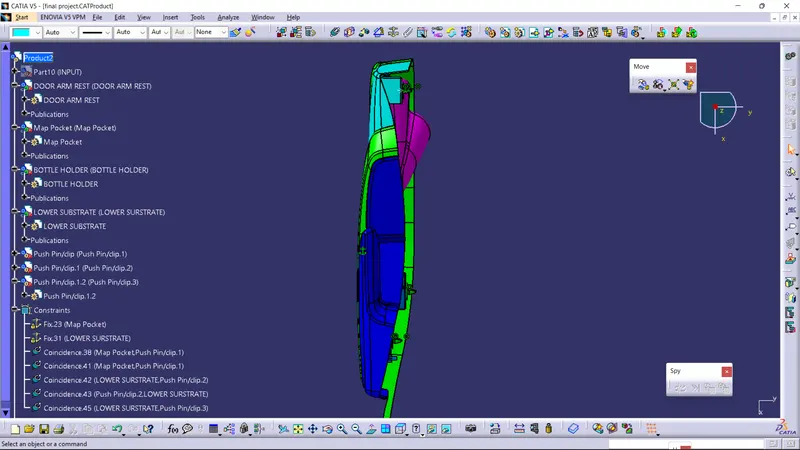
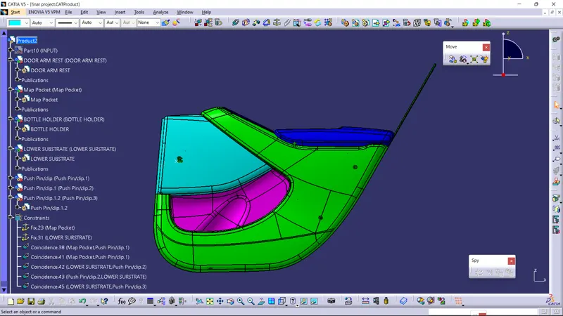
- CONSTRAINT-Constraint are used to do assembly of part to other to properly and to each other. Here constraint is used to assemble the push pin with the dog houses. I used to constraint per dog house, push pin assembly. One id coicident between the key hole axis and the push pin axis. The other also coincident between the upper surface of dog house and the lower side ot connecting surface of the push pin.
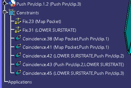
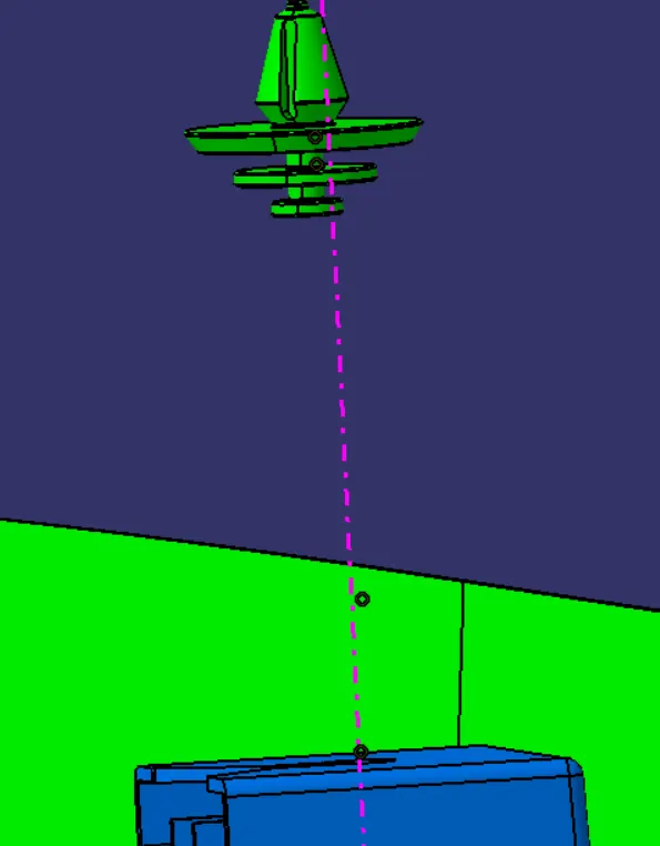
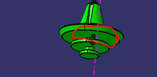
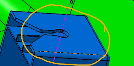
FOR THE THICKNESS OFF ALL PARTS I USED CLOSED AND THICKEN SURFACE. FOR THE DOG HOUSE THICKNESS I USED THICKEN COMMAND AND OTHERS I CREATED WITH THE HELP OF CLOSED SURFACE COMMAND.