Week 11 - Final project
WEEK 11- FINAL PROJECT
AIM:
To interior part from the inputs of class A surface along with master section by deelopment of vehicle interior door trim using Catia V5 with given class A surface along with Mater section. also create the side Attachement fewature as per desing rules. followed the desing rules in tired and OEM industries in CATIA V5 constrained.
OBEJECTIVE:
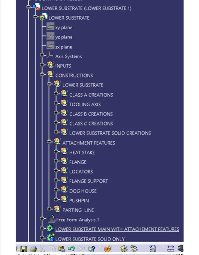
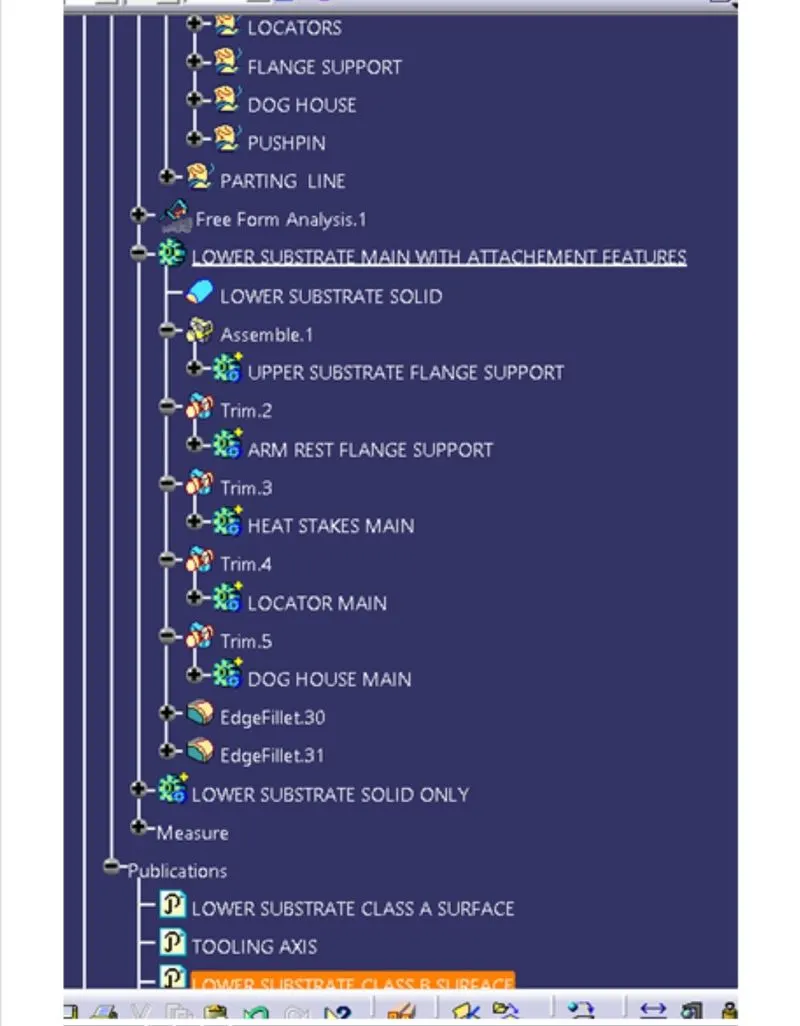
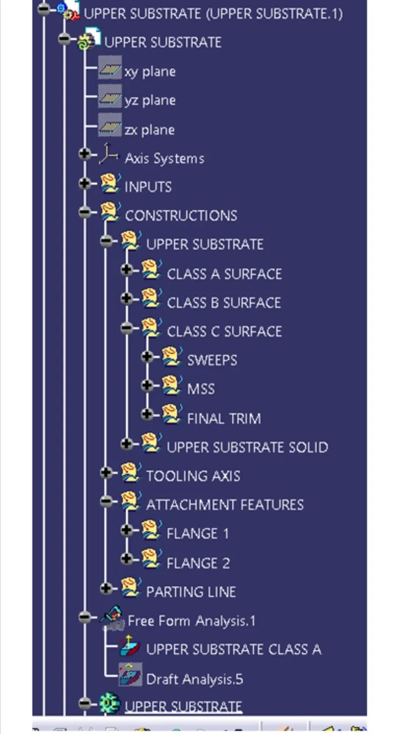
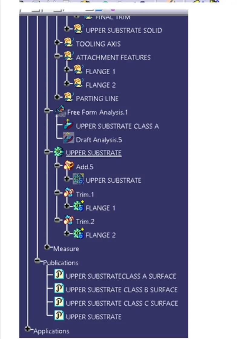
* To create the mounting features as per desing guidelnes in the industry and with master sections. Ensured Proper Tree structure.
* To create of Draft analysis & Tooling analysis. creating of parting lines and check tooling feasibility. To perfrom Draft analysis & Tooling analysis thickness part using master section for reference.
INTRODUCTION:
These require one of the toughest requirement among the interior parts of the car. this should be desined to with stand the load while being less than the thickness and also to protect the occupants during collisions. door currently have an inner full width panel consisting of electronic window, central locking system and speakers. these panel typically consists of a foamed core covered with either textiles or plastics that tooling analysis.
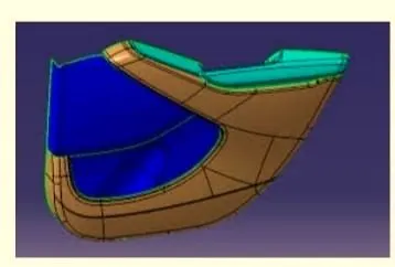
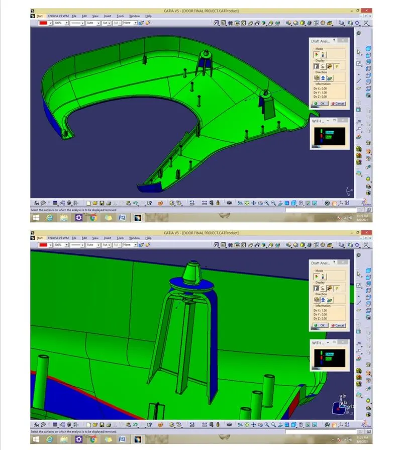
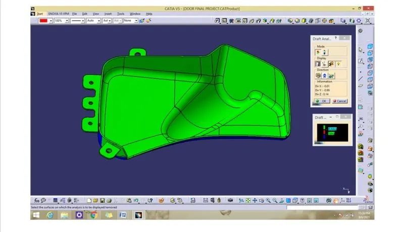
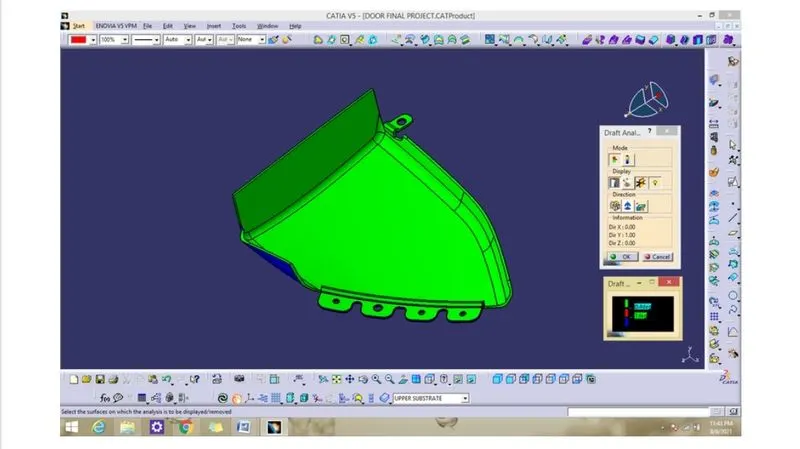
Here the draft angle is given as 3 degree hence we achived green colour on top surface. hence it accepts the draft angle for the surface so we build good quality component. if the surface appears red in colour while analysing it is not accepeted. now we check colour variant scale to ensure the maximum area draft angle is colour respectively.
PROCEDURE:
Drag a compass and place it on axis that we created view . lock the orientation of the compass. check all the boundary whether it has connected or not. After analysis the above model there is an chance for undercut when we consider tooling axis from we have to create tooling axis on also given sureface.
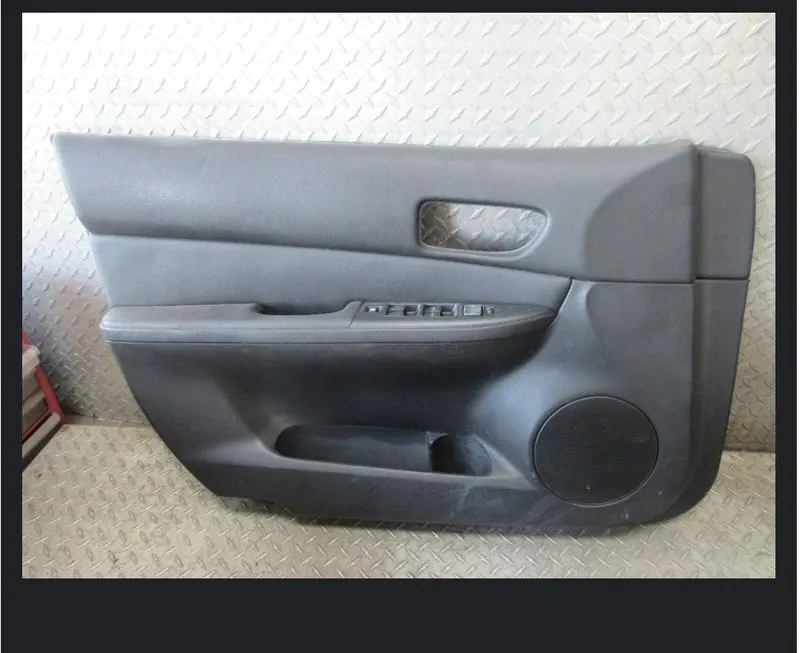
The input class a surface is containing four different parts so class b and c for all the surface has been created in seperate catpart also performing draft analysis and tooling axis seperatly.
TOOLING AXIS LOWER SUBSTRATE:
DRAFT ANALYSIS:
To create a point on centre of gravity of part by using measure interia command and insert a axis system on the point as shown below. create a piont direction line parallel to the y axis and named as Tooling axis as shown below. bisecting line by the reference of tooling facing y direction and tooling axis.
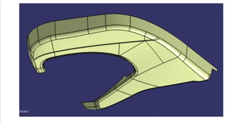
After analysis the above model the best tooling axis is y direction. create a point on centre of gravity of part by using measure inertia command and insert a axis system on the point as shown below.
TOOLING AXIS:
create a point direction line parellel to the y axis and named as Tooling Axis as shown below. check all the boundary whether it has connected or not. best tooling direction which should be easy for draft.
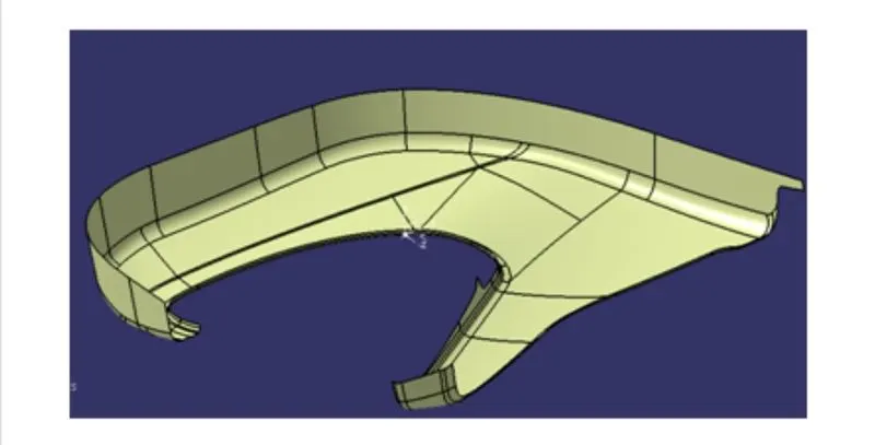
Door currently have an inner full width panel consisting of electronic. windows these panel typically the tooling direction is used to find the direction in which the part is removed from the core and cavity.
METHODOLOGY:
CREATING THE TOOLING AXIS:
The tooling direction is used to find the direction in which the part is removed from core and cavity. the draft angle should be positive to the tooling axis to manufacture the component easily. the step procedure of creating the tooling axis is given below.
STEP 1:
SIMULTANEOUS PRESSING AND INJECTION MOLDING TECHNOLOGY:
A technique where natural fiber base material and resin components are pressed simultaneously. Enables reduction in weigth as well as increased efficiency of production process.
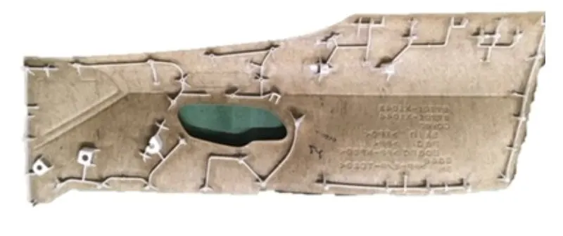
The molding the tool axis for map pocket by create a point on surfaces respectively to the 0 value. it automatically create at mid surface and generate the to mid surface and generate the line to the direction of y axis.
STEP 2:
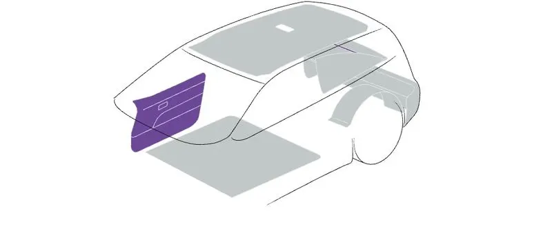
DOOR TRIM:
Next to the dashboard the door trims are the interior parts that contain the most controls and decorative parts. As such there is a necessessity for balancing gap between parts as well as an overall sense of unity between the numerous parts.
STEP 3:
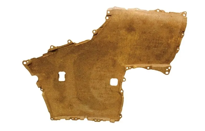
EXPANDED KENAF BASE MATERIAL:
Door trim base material making use of the eco friendly highly CO2 absorbing annual grass kenaf. Reductions in the weight of vehicle parts contributes to an over all reduction in CO2 emissions over the products lifecycle.
STEP 4:
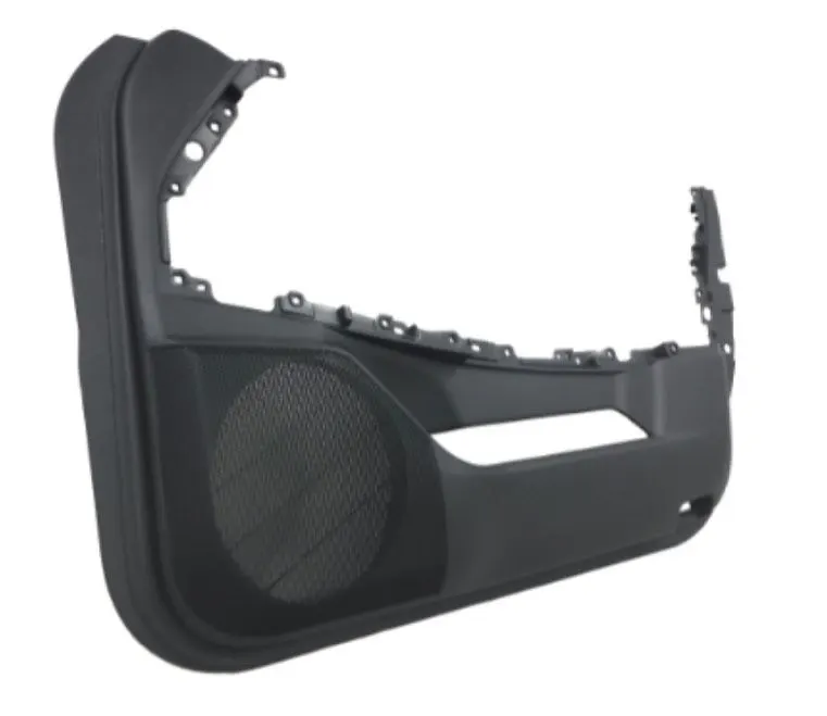
LIGHTWEIGHT MOLDED FOAM DOOR TRIM WITH HIGH IMPACT RESISTANCE:
This door trim utilizes toyota boshuku high impact resistance plastic a plastic material featuring world class impact resistance. our foam molding technologies enable us to create a door trim that reduces weight by approximately 20% compared to convential base materials while maintaining high impact resistance.
STEP 5:
DOOR ILLUMINATION:
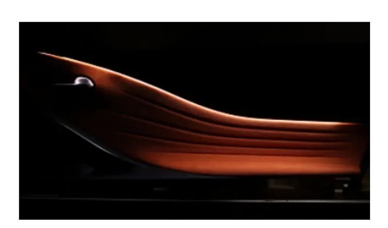
Ambient illumination fitted along the form of the door trims. illumination of the curved form of the trims gives rise to subtle shadowing which produces an elegant atmosphere and feeling of luxury.
CREATION THE B SURFACE:
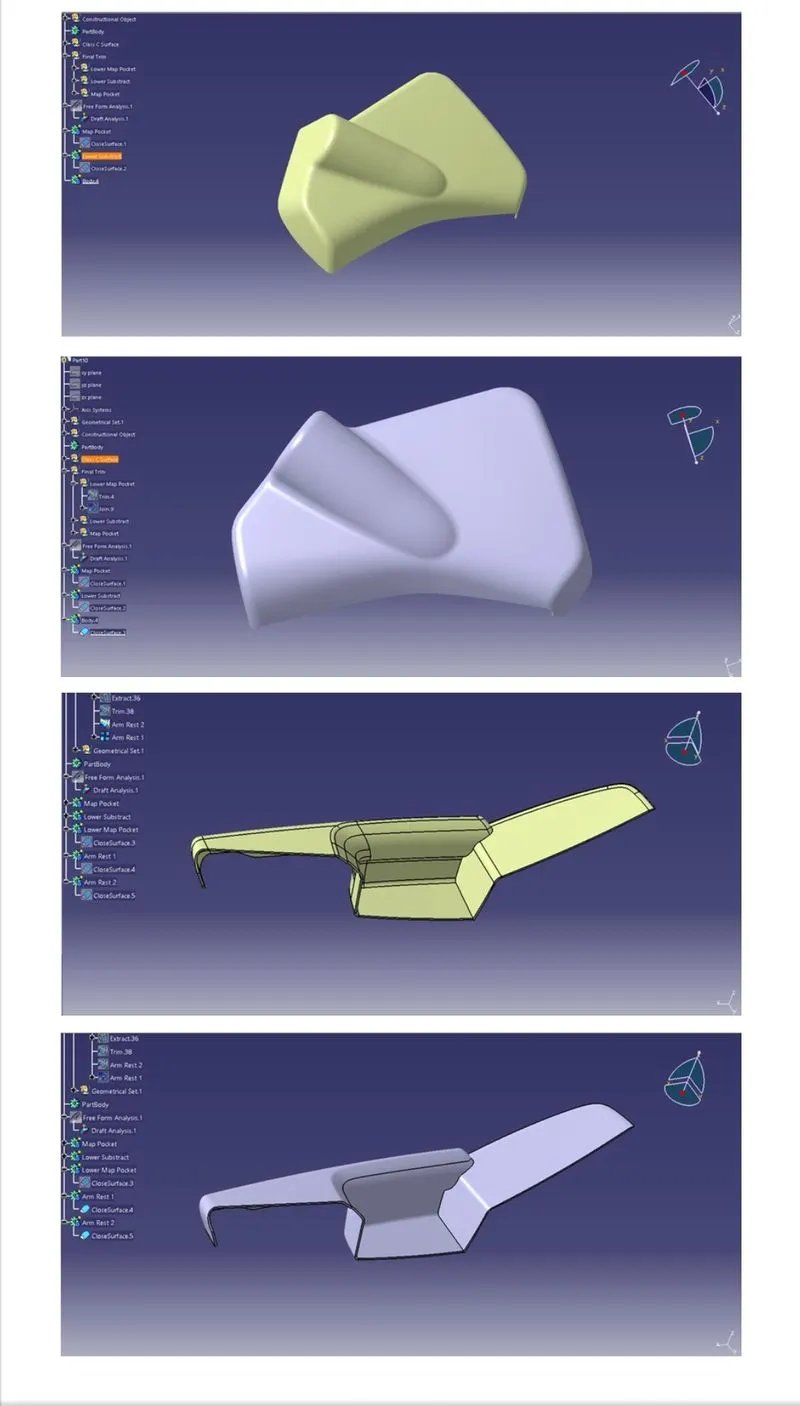
Create the B surface by extracting the class A surface by each surface separately it is offset to certain distance making point on the intersection as shown below.
Achived the B class surface by extracting and offset the class A surfaces.
THE FINAL PLASTIC COMPONENT:
To make the final component the class C surface is trimmedwith class B surface the output will get the component with 2mm thickness of surface and it is converted into solid body using insert body option in part desing as shown below.
CALCULATION:
Lower substrate=1.371kg
Bottle holder=0.344kg
Arm rest=0.187kg
Upper substrate=0.224kg
the total weight of the product is=2.126kg
DOG HOUSE RULES:
B=4MM
T=2.5MM
C=0.4*T=1MM
Extract the sweep and offset to B=4mm and C=1mm on all direction like the below.
DRAFT ANALYSIS REPORT OF UPPER SUBSTRATE:
DRAFT ANALYSIS REPORT OF BOTTLE HOLDER:
DRAFT ANALYSIS REPORT OF ARM REST:
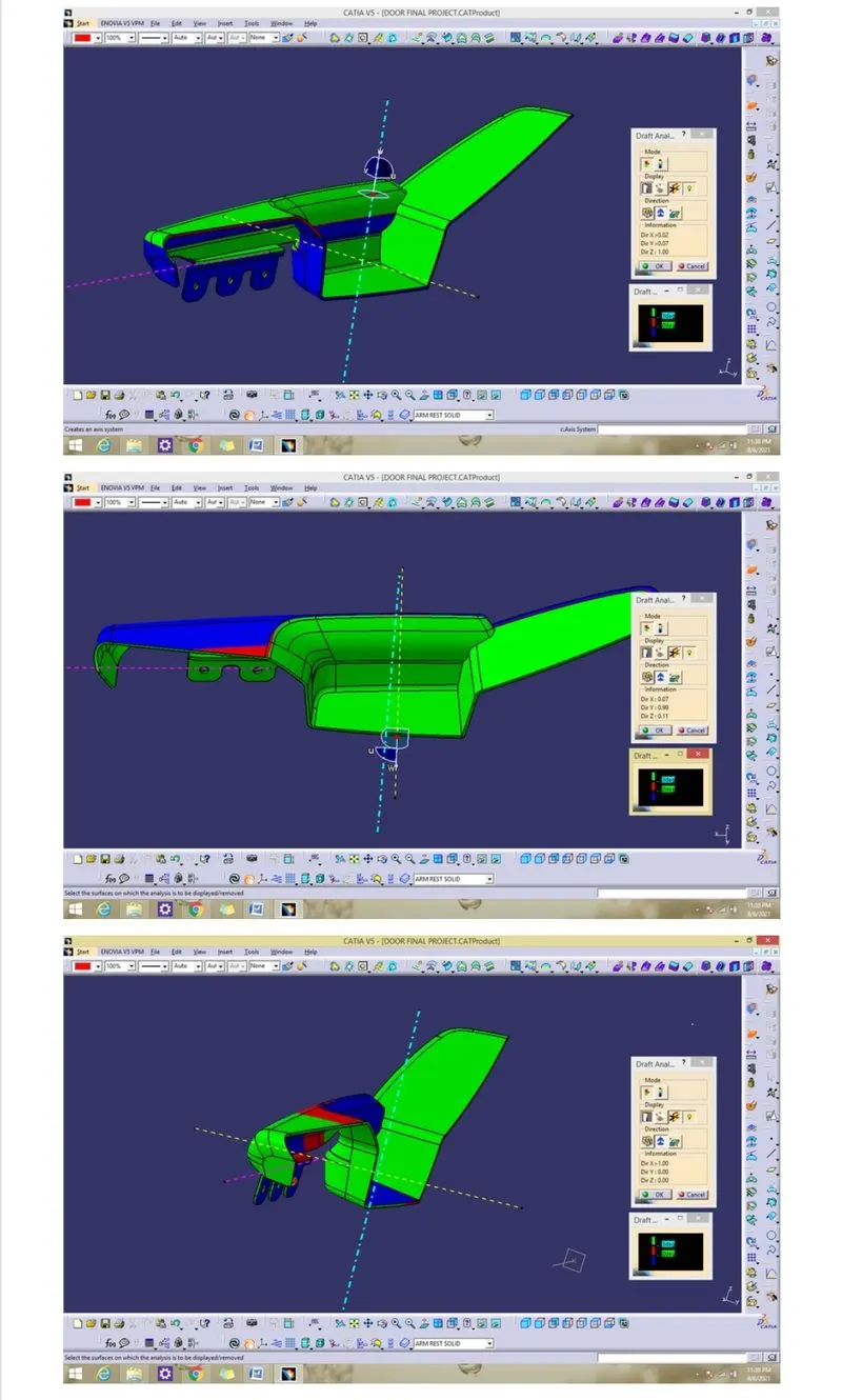
DRAFT ANALYSIS REPORT OF LOWER SUBSTRATE:
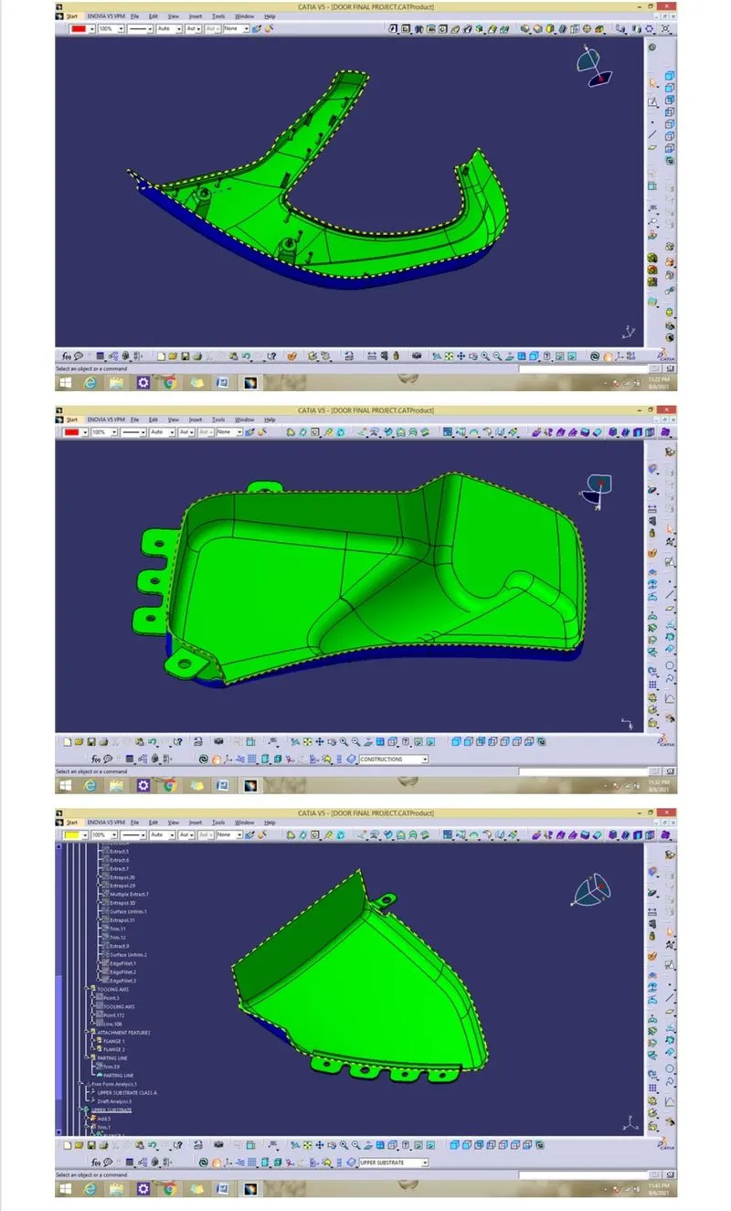
CREATION OF PARTING LINE:
Partline line is used to the differentiate between core and cavity.
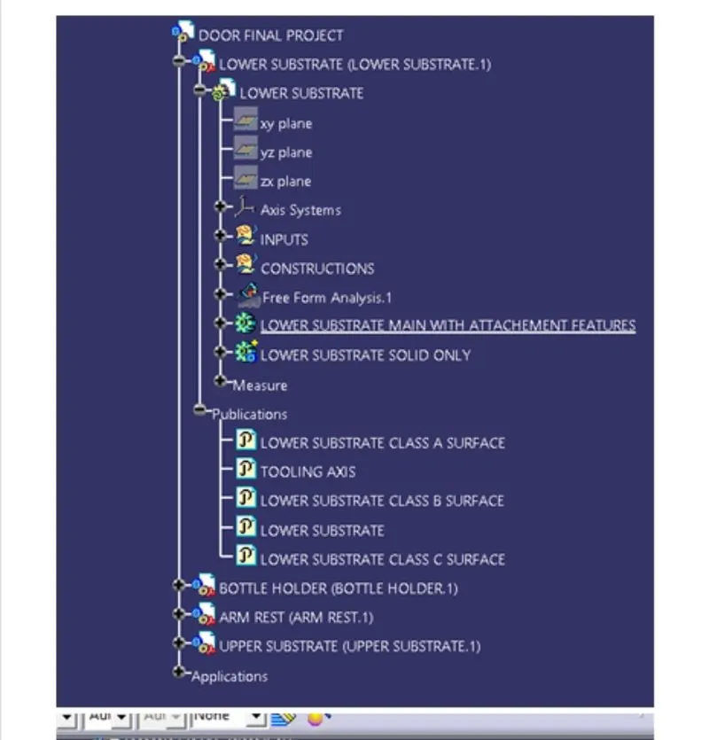
TREE SRUCTURE:
CONCLUSION:
The creation of the car interior door trim is designed using the given class A surface as the input and class B and C surface created with the given master section attachement features heat stakes flanges dog hosue and push clip are created using the design rules. the analysis has will verify that all surfaces are facorable for being pulled from a cavity it may also highlight or given insight to defect areas.let's thus the door interior part has been created from the inputs of class A surface along with master section im OEM industries in to assemble the heat stake to lower substrarte solid.