Week 11 - Final project
OBJECTIVE:
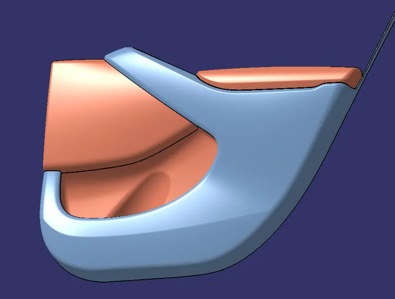
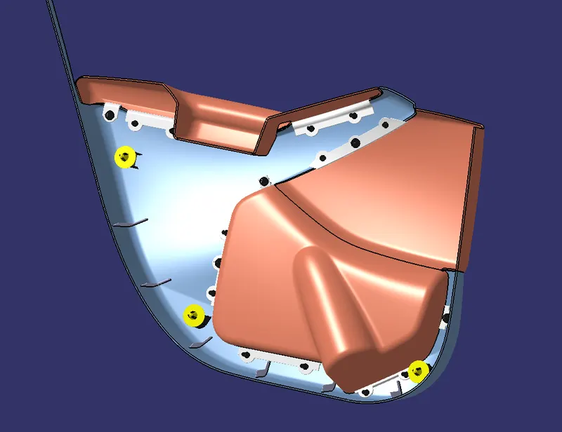
To create a production ready model of the given "DOOR TRIM PANEL" Class-A surface including all the engineering features according master sections as prescribed by the OEM standards.
THESIS:
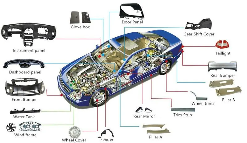
The role of plastic in the design and manufacturing of automotive vehicles has never been more essential, with stringent regulations and changing consumer habits driving demand for more affordable, lightweight, and fuel-efficient vehicles. Fuel efficiency has become one of the most important features in automotive vehicle design due to the rising fuel prices and stricter environmental regulations.
Currently, there are about 30,000 parts in a vehicle, out of which 1/3 are made of plastic. In total, about 39 different types of basic plastics and polymers are used to make an automobile. More than 70% of the plastic used in automobiles comes from four polymers: polypropylene, polyurethane, polyamides and PVC. Plastic has become one of the key materials required for the structure, performance, and safety of automobiles in recent years, with growth in plastic consumption being driven by light weighting trends for fuel efficiency and consequently lower greenhouse gas emissions. The high absorption properties of plastics also allow the vehicle to meet stricter safety standards, while the use of engineering plastics allows for minimization of the mass of parts used in vehicles as they offer more design freedom compared to metals.
DESIGN PROCEDURE:
- Extracting the Class A Surface received from the styling department.
- seggregating the data into serperate geometrical sets.
- Analyzing the model.
- Creation of Tooling axes.
- Draft Analysing the class A surface.
- Creation of Class-B and Class-C surfaces.
- Making a closed surface of the components by trimming the Class-A, B, and C surfaces.
- Converting the closed surface into a solid part.
- Draft analyzing the solid parts for Mould release.
- Creation of Engineering features according to the Master sections and the OEM Standards.
- Assembling all the components together.
Extracting the Class A Surface received from the styling department:
The Class-A surface and the master sections are received from the styling department,from which a fully functioning, production ready model has to be created.
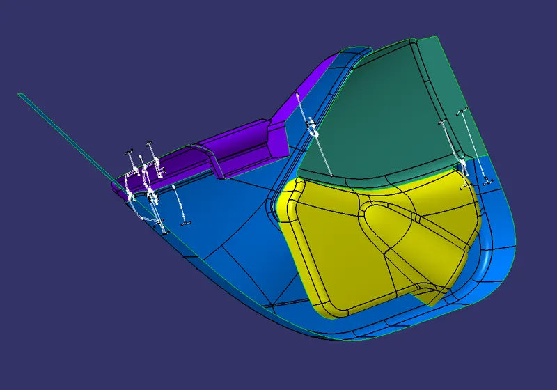
Creation of Tooling Axes:
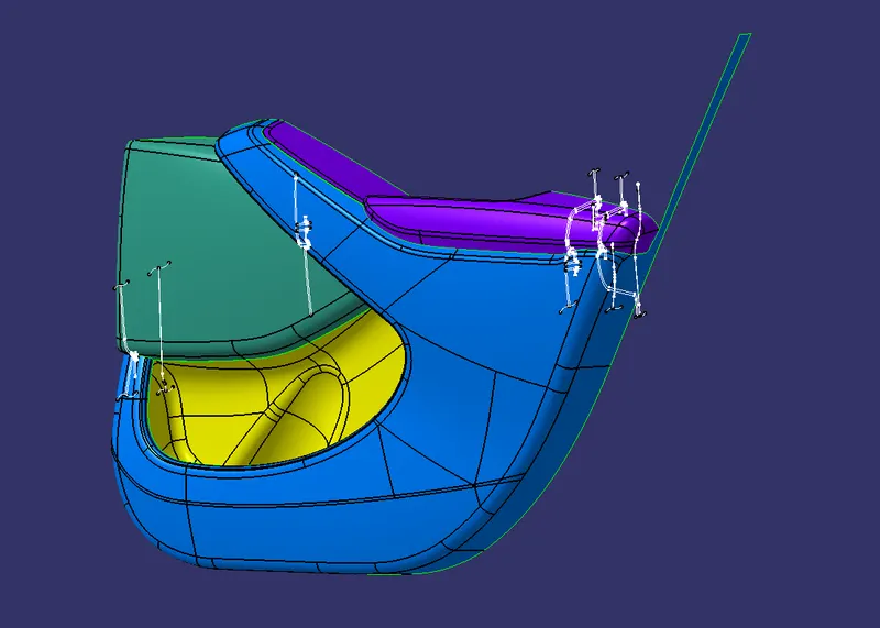
The tooling axes are created in order to analyze the mould release of the component during production. The drafts on the component are given according to the Tooling axis for proper and clean Ejection of the Component.
Creation of Tooling axis using "Bisection Method".
- In this case, the tooling direction is considered to be Z-direction as it has the easiest ejection and least complications compared to other directions.
- Initially an axis system is created at the centre of the model. a "Dummy Tooling Axis" is created along the Z-direction of the model.
- Then an "intersection" is created using the "Dummy Tooling Axis" as the first element and the class-A surface which is "FAN COVER" (in this case) , as the second element.
- The intersections are created along X-direction as well as Y-direction for the surface.
- For each intersection,the drafted surfaces are extended to create a bisecting line.
- The "Bisectors" of each intersection are again Bisected with each other to generate the "Tooling axis".
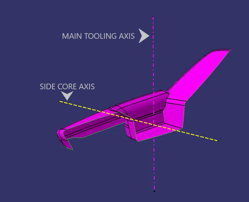
Draft Analysing the class A surface:
The given Class A surface is Draft analysed to check for mould ejection. Draft analysis is performed on each of the Class-A surface of the components to ensure that the part can be produced. if not, the class-A surface is sent back to the styling department for any corrections to be made.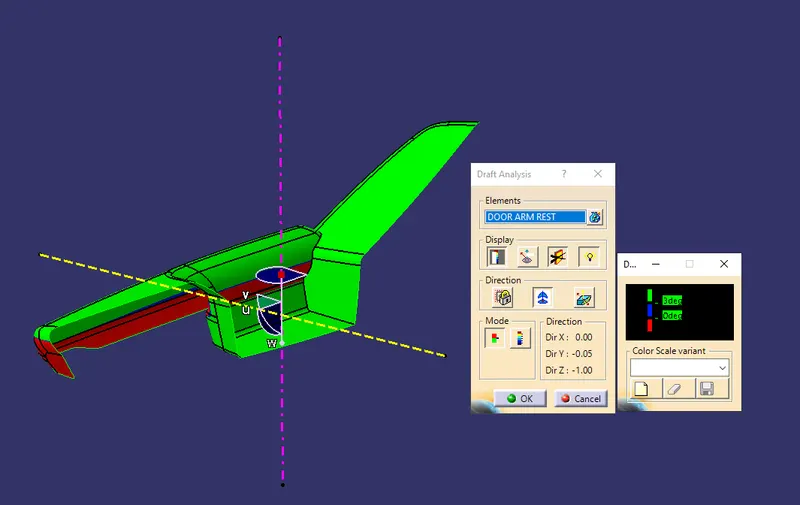
Creation of Class-B and Class-C surfaces:
Once the class-A surfaces are analysed, it is our job as a Design Engineering to create a solid part from the given Class-A surface. in order to do so, the Class-B and Class-C surfaces have to be created. the Class-B and Class-C surfaces are surface which define a solid body.
The Class-A can be defined as the surface which the consumer would look,touch and feel. the Class-A surface is the surface which has to be asethetically pleasing to watch and feel. hence the class-A should not have any defects as customer satisfaction plays a major role.
The Class-B surface is the surface which can be considered as the "Off-set'ed Class-A". the Class-B surface is the surface that contains all the engineering features to make the component allign with the other mating components. The features on the Class-B surface also have a job to make the component stronger and also compatible with other components.
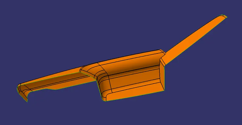
The Class-C surface is the surface which joins the Class-A and class-B together. the Class-C is usually the thickness of the component.
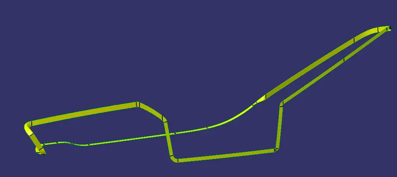
In the automotive industry, and also other industries, the Class-B and Class-C are usually hidden from the consumer. hence the Class-A surfaces are given priority for a greater surface finish and lesser defects.The class-C should be created following a minimum Draft Angle of 3 degrees for mould ejection.
The creation the Class-A, B, and C surfaces are created using "Generative Shape deisgn" whilst following the Master Sections given by the Stying department. The Class B surface is created by offsetting the Class-A surface to the prescribed thickness. The Class-C surface is created by extracting the boundaries of the Class-A and sweeping them. later, The Class-A,B and C surfaces are trimmed to from a closed surface of the Component.
CLASS-A
CLASS-B
CLASS-C
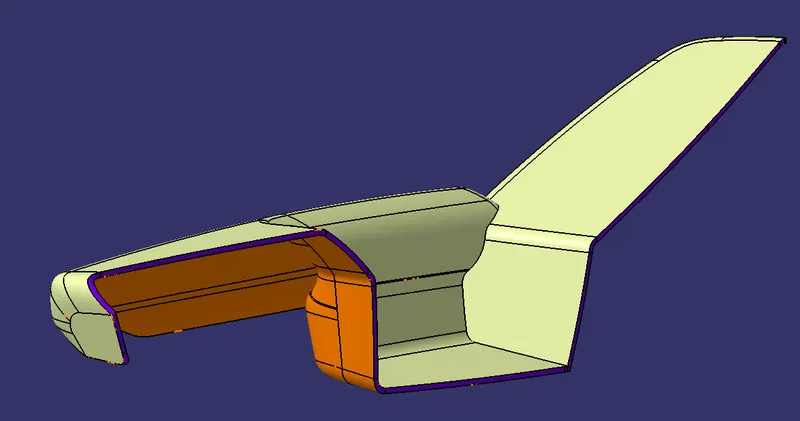
Conversion of "Closed Surface" into a "Closed Body" :
The closed surface created in the previous stage is hollow inside and has no material nor thickness. but since our actual component is completely a solid body and has no hollowness, the surface has to be created into a "solid part". in case of a hollow object, the surface has to be converted into a part body but the surface has to be thickened for the real world scenarios.
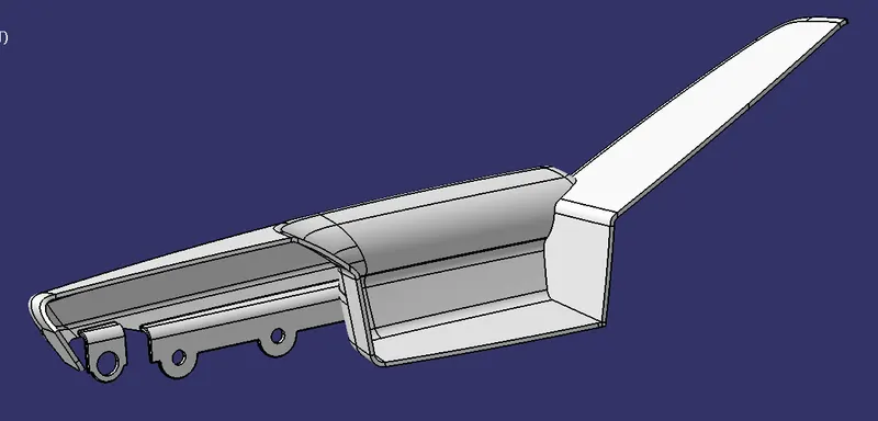
Draft Analysis of the solid parts:
once the "Closed Surfaces" are converted into "Closed Bodies" , the components are draft analysed to check the Mould Ejection. the solid body is analysed using Draft analysis to check whether will the component come out smoothly out from the core and cavity. this is a critcal stage since improper or Flat faces may lead to difficulty in ejection of the component, resulting in damaging of the surface finish,damaging the component or even no possible ejection of the component. situations like these can be avoided if proper drafts are given to the component,saving a lot of time and expenses. according to the standards, a minimum draft angle of 3 degree's with respect to the tooling axis has to be followed,which works for most of the plastic components not only specific to the automotive industry.
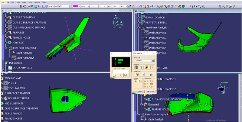
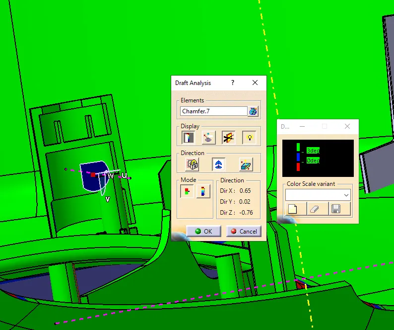
Draft Analysis for Dog houses:
for the features like dog houses, the side core is used as only 1 core is not enough to eject the component from the mould.
Creation of Engineering features according to the Master sections:
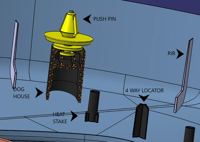
The engineering Features are the most important features for a automotive plastic components. The engineering features comprises of features like,Flanges, Ribs, Screw Bosses, Heat Stakes, 4 Way Locators, 2 Way Locators, etc.
The engineering features not only decide "How?", "Where?" and "Why?",the components mount on, but also help in over-coming surface defects and making them structrally more rigid.
Assembly:
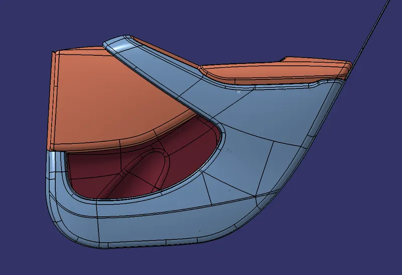
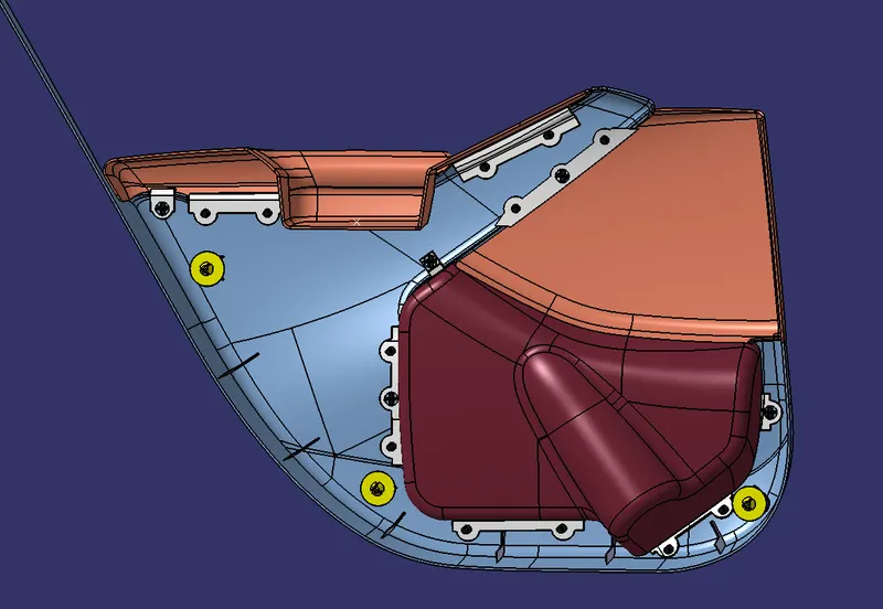
Once every component is created into a solid component with all engineering features and are draft analysed, The components are to be assembled to check the fit of the components. The Assembly of the components is performed the "Assembly Workbench".
the below images show the assembly of the components together.
FINAL ASSEMBLY: