Week 11 - Final project
Objective: To make a solid body of a side door trim of a vehicle from the given class As of 4 parts of the door trim which are Lower Substrate, Bottle Holder, Map Pocket, and Door Armrest. Also, B side features like doghouse, heat stake and locator should be added, all obeying the design rules and guidelines.
Theory:
Role of plastics in the Automotive industry
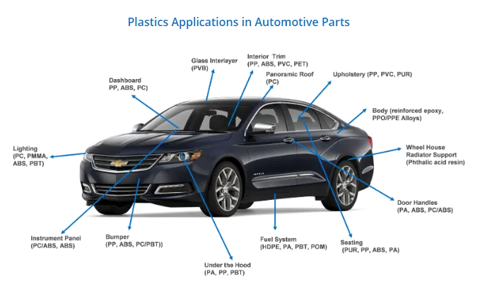
The automotive industry is the third most important consuming sector of polymers after packaging and building and construction.
The role of plastic in the design and manufacturing of automotive vehicles has never been more essential, with stringent regulations and changing consumer habits driving demand for more affordable, lightweight, and fuel-efficient vehicles. Fuel efficiency has become one of the most important features in automotive vehicle design due to the rising fuel prices and stricter environmental regulations.
There are about 30,000 parts in a vehicle, out of which 1/3 are made of plastic. In total, about 39 different types of basic plastics and polymers are used to make an automobile. More than 70% of the plastic used in automobiles comes from four polymers: polypropylene, polyurethane, polyamides and PVC. Plastic has become one of the key materials required for the structure, performance, and safety of automobiles in recent years, with growth in plastic consumption being driven by light-weighting trends for fuel efficiency and consequently lower greenhouse gas emissions.
Manufacturing Process:
Injection Moulding:
Injection moulding is one of the most commonly used production processes for plastics. It offers a viable solution for the mass production of high-quality injection automotive parts from a broad range of polymers. In the automotive industry, where consistency, safety, and quality are of utmost importance, automotive plastic injection moulding is an important manufacturing process.
Plastic injection moulding is the process of melting plastic pellets that once malleable enough, are injected at pressure into a mould cavity, which fills and solidifies to produce the final product.
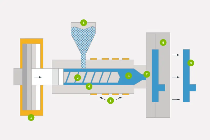
From left to right, the components of a rapid injection moulding press include ram (1), screw (2), hopper (3), barrel (4), heaters (5), materials (6), nozzle (7), mould (8), and part (9).
Tooling Direction
Tooling direction is the direction the mould takes to make the part. It is basically the direction that the mould pulls apart. The mould is built in two separate pieces, a cavity side and the core side. The core pulls apart from the cavity and that is the Tooling Direction.
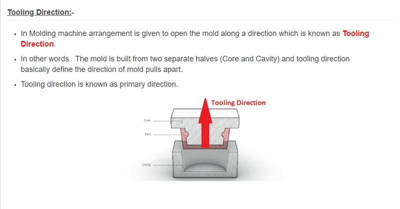
Core is the male part which forms the internal shape of the moulding. Cavity is the female part that forms the external shape of moulding.
Parting line is the line of separation on the plastic part where the two halves of the plastic injection mould meet, i.e. where the core and cavity meet.
Design for Manufacturing & Assembly (DFMA)
Design for Manufacturing and Assembly is an engineering methodology that focuses on reducing time-to-market and total production costs by prioritizing both the ease of manufacture for the product’s parts and the simplified assembly of those parts into the final product – all during the early design phases of the product lifecycle.
Before becoming the singular philosophy it's known as today, DFMA used to be considered as two distinct methodologies: Design for Manufacturing (DFM) and Design for Assembly (DFA).
DFM is concerned with selecting cost-effective raw materials and attempting to minimize the complexity of manufacturing operations during the product design phase in order to reduce the overall manufacturing time and costs for product components. Similarly, DFA is concerned with reducing the product's assembly time, costs, and complexities by minimizing the number of individual parts, assembly steps, and the potential for variability in build quality.
Function of Heat Stake, Locator, Doghouse, and Ribs
Heat staking technology is quite simple in concept. Whenever two or more components need to be attached to one another, and at least one is made of a thermoplastic, a combination of heat and pressure can be used to reform the plastic to the many shapes or profiles to retain or join the parts together.
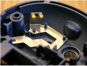
Heat Stake (cylindrical structure on the left)
A 2-way locating pin restricts motion along 1 axis (or 2 degrees of Freedom). Likewise, a 4-way pin restricts 4 degrees of freedom along 2 axes.
Dog house is a 4 sided box attached to a flat surface which usually requires a riser/slider to mould. In other words, it has 3 sides and a roof, where the roof usually has a hole for attachment purposes.”
Ribs can be added to parts to add rigidity or stiffness. Adding ribs allows for a part to increase strength and bear a higher load.
Procedure:
These are the given class A surfaces. These have been slightly modified from the original due to imperfections and instability in the original one.
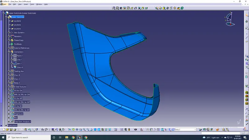
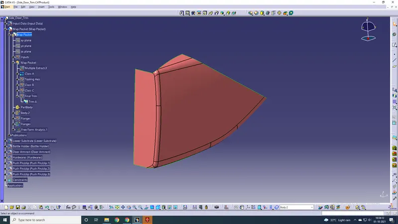
Lower Substrate Map Pocket
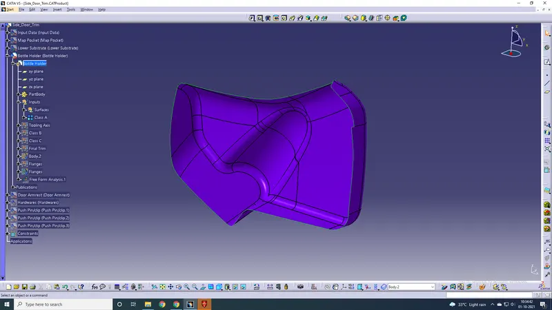
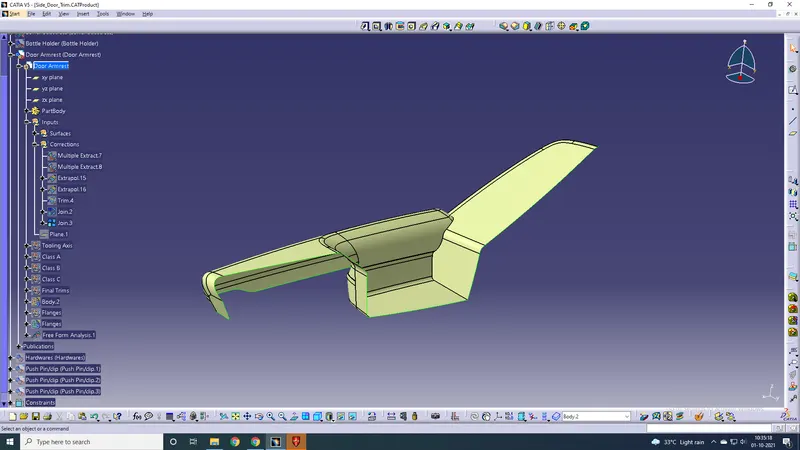
Bottle Holder Door Armrest
Making Class B and C for the lower substrate
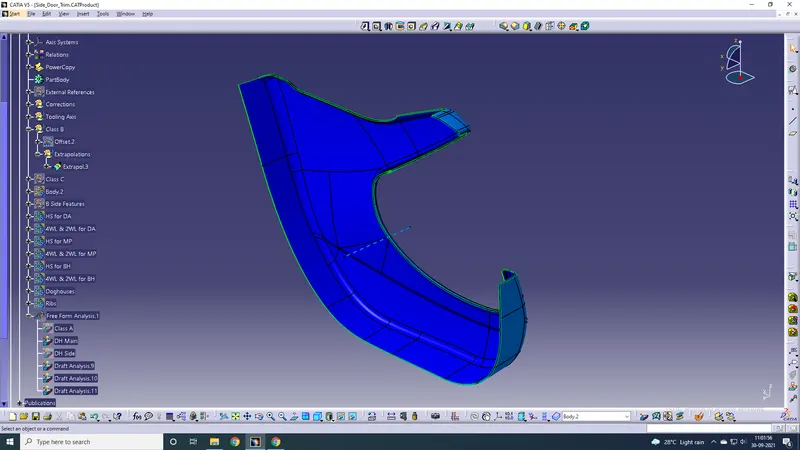
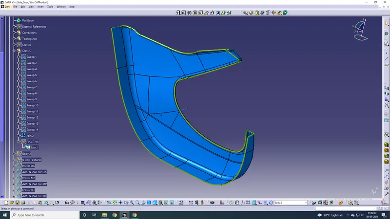
Tooling axis for the LS has already been made, which is shown by the dashed blue line.
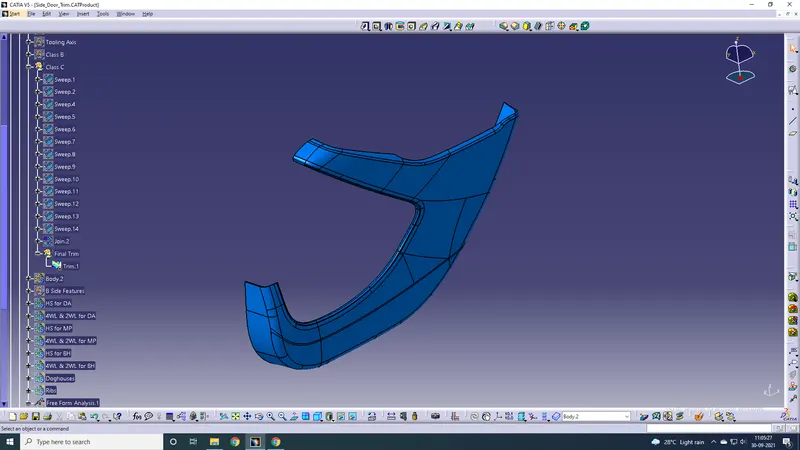
Final trim and making the solid body
Draft Analysis for LS
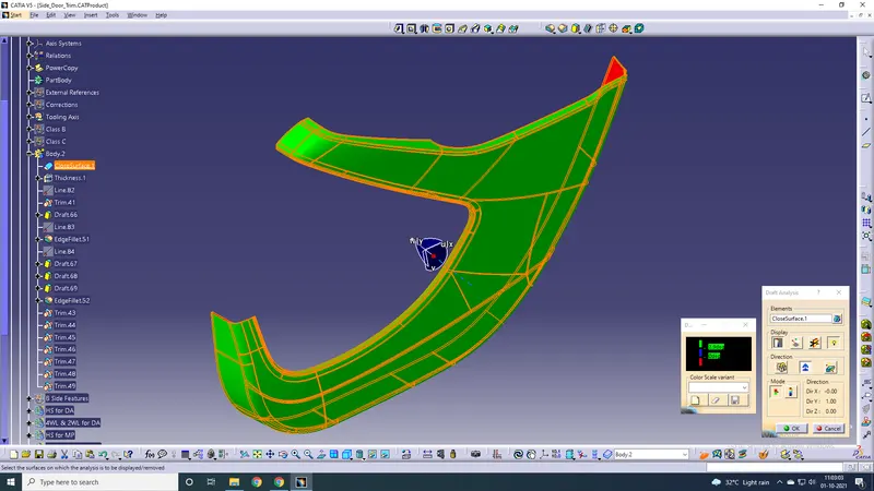
Similarly making solid bodies and doing draft analysis for the rest.
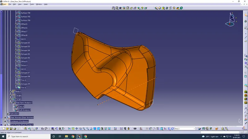
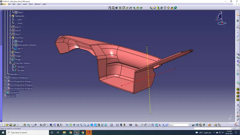
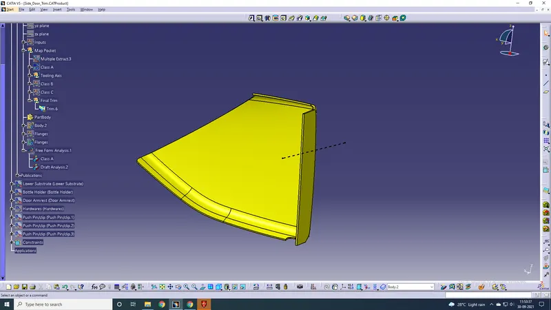
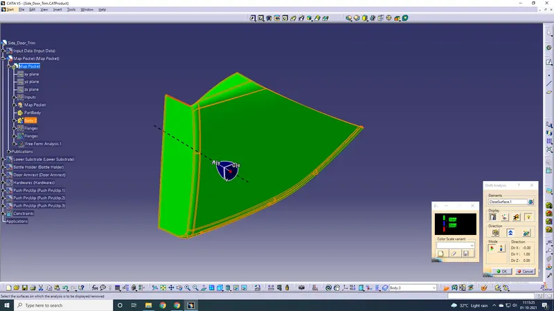
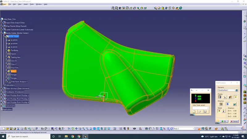
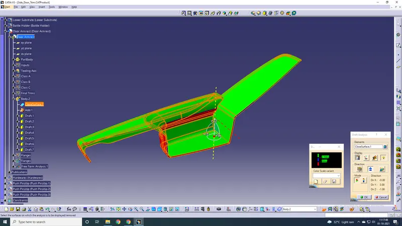
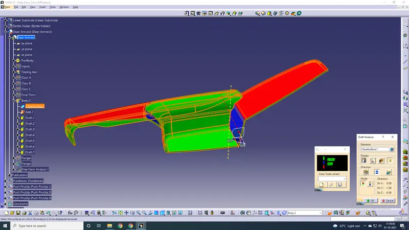
Main tooling axis Side tooling axis
Creating B Side Features
Heat Stake with Ribs
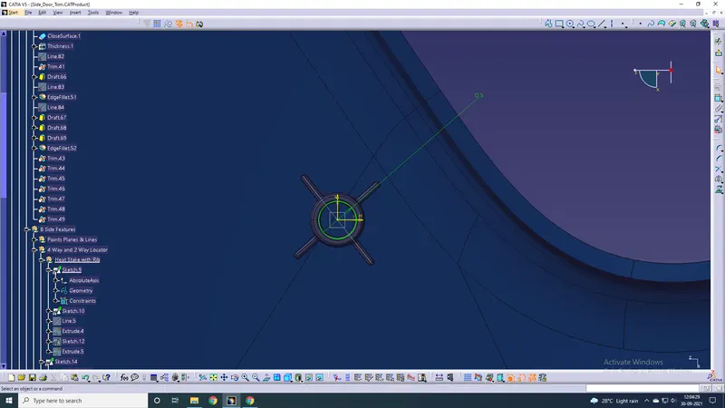
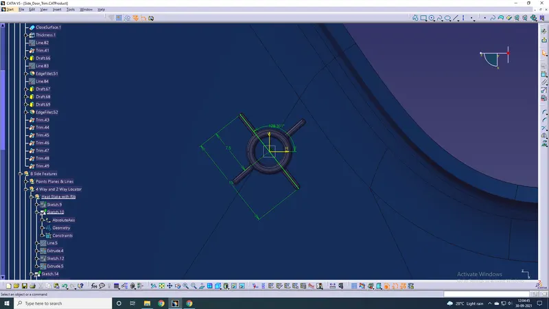
A circle of diameter 5mm was made and thickened outside 2mm to get a 7mm dia. circle outside. Ribs were added on both sides for strength to the heat stake. 15mm ribs were provided.
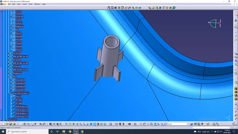
Solid heat stake
Multiple heat stakes were made using translate function on various areas of the doghouse. These heat stakes support the bottle holder, map pocket and door armrest.
A draft of 0.5 was given to the heat stakes and their ribs. Note that inside draft for the stake will be in the opposite direction to the outside.
Finally, the heat stakes were union trimmed with the lower substrate.
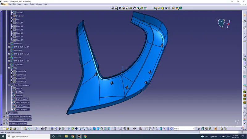
Heat Stakes for BH
Similarly, 4-way and 2-way locators were made. Note that the height of the locators should be more than that of the heat stakes.
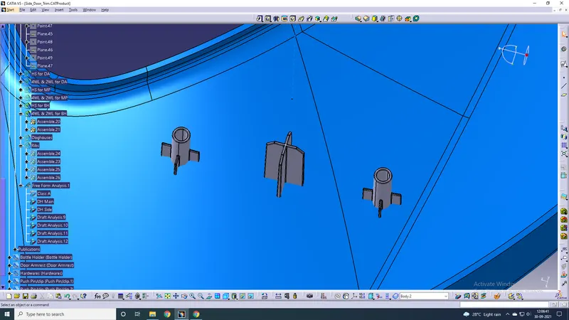
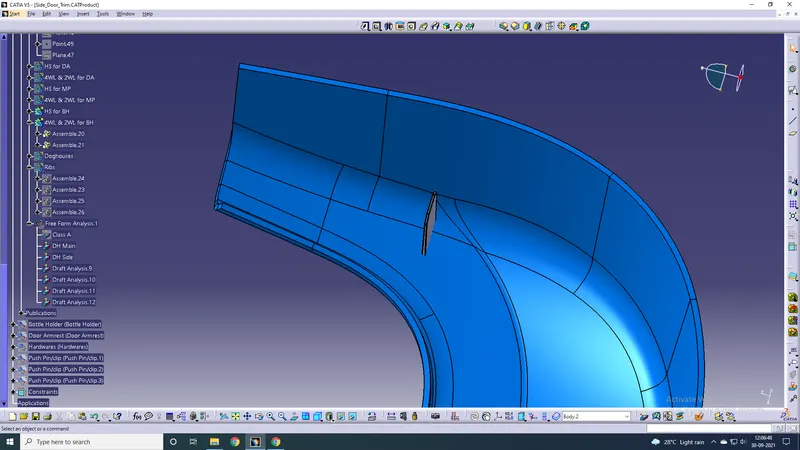
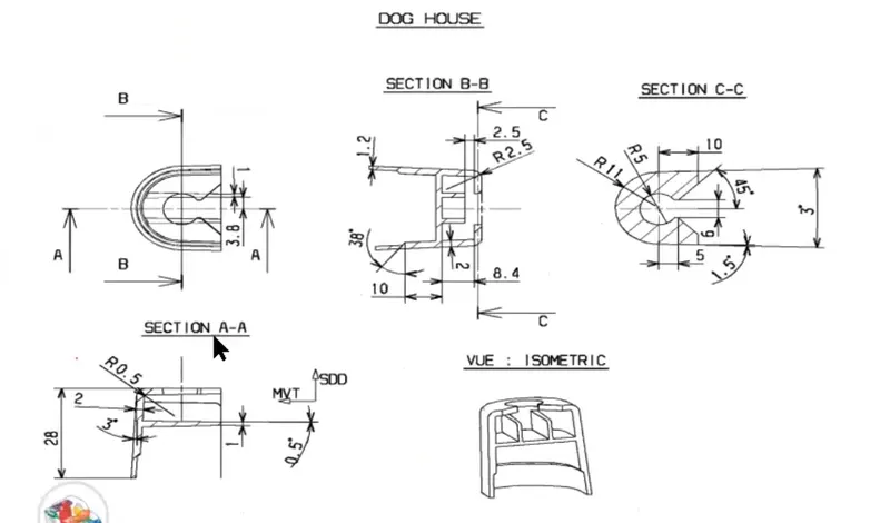
Doghouse
The sketch for creating the doghouse is given below
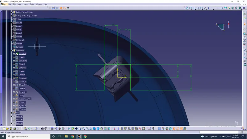
4 doghouses were added on the lower side of the LS.
Pad this sketch upwards to a height that is about 5mm from the top surface of the LS.
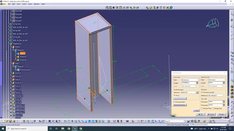
Final output
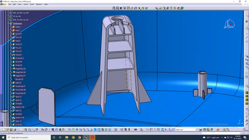
The hole on the top surface of the doghouse is for placing the push pin, which we'll come to later.
Ribs on the LS Sides
4 ribs were made on the sidewalls of the LS for extra rigidity.
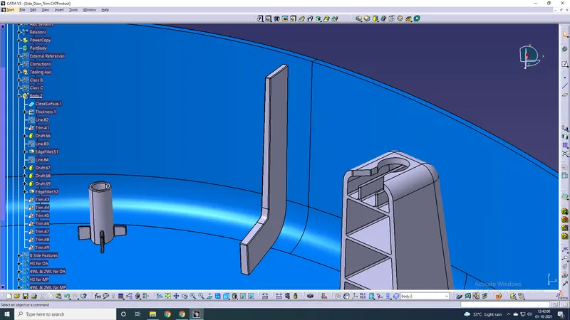
All B-side features have now been made. Heat stakes with ribs and locators (4way and 2way) were made for the Lower Substrate, Bottle Holder, Map Pocket, and Door Armrest. Ribs were also made on the walls of the LS.
Depicted below is the final output of all B side features on the LS made.
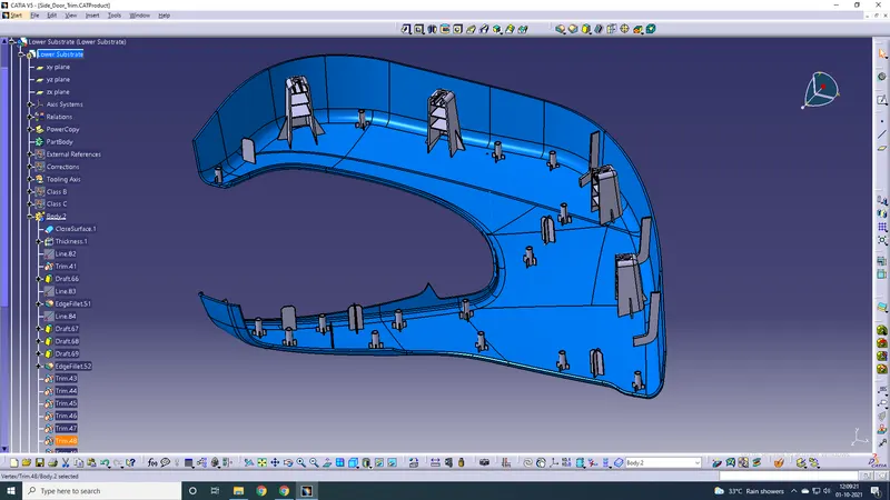
B side features on the LS
Now we need to make flanges for the BH, MP, and DA. The flanges surround the HSs and locators. The clearance b/w flange and HS should be 0.5mm and that b/w HS and locator be 0.1mm.
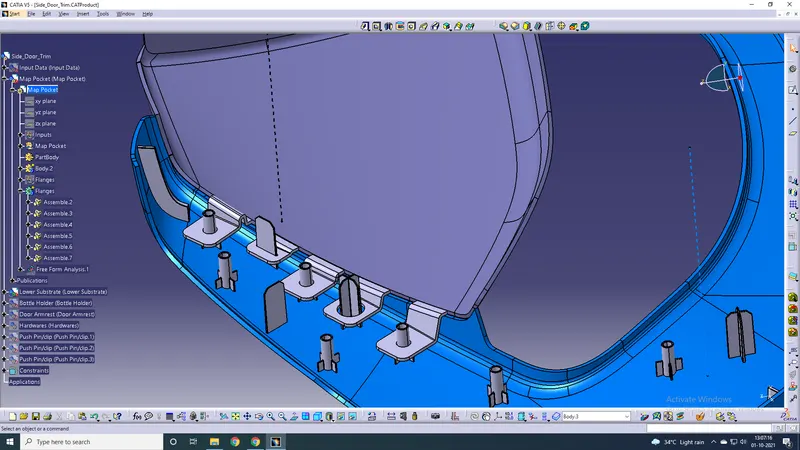
Flanges for MP
Creation of the flange was started by taking an extrude from the upper edge of the solid body and making directional changes according to the HS/locator placement.
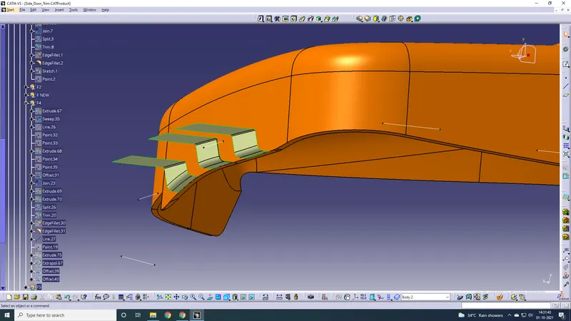
All flanges have been provided now.
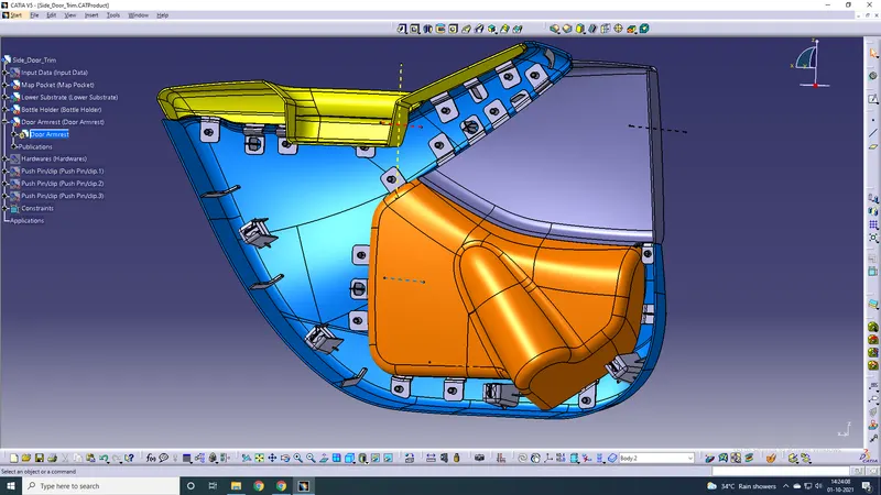
Draft analysis for B Side features
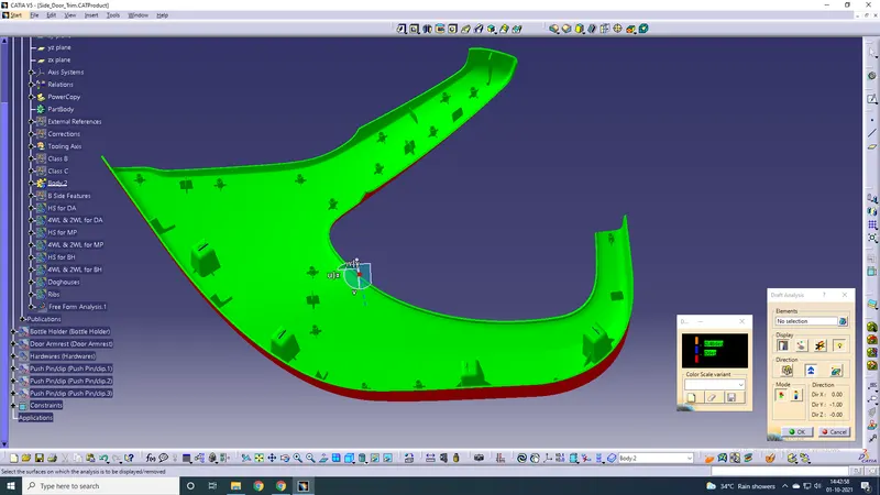
Draft Analysis for HSs and locators
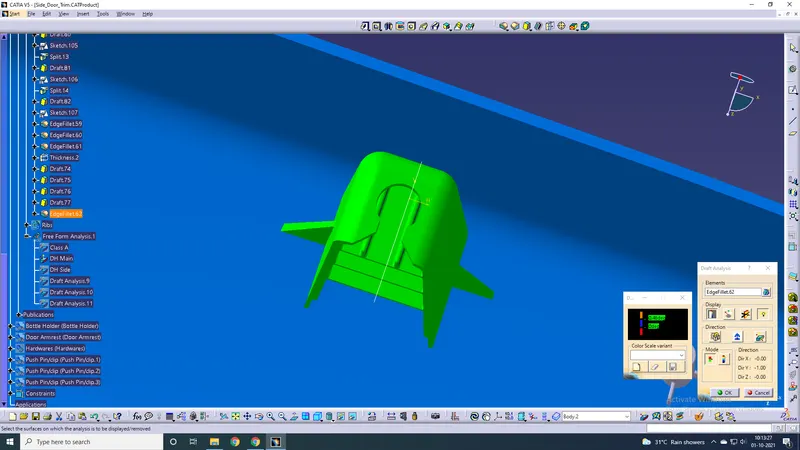
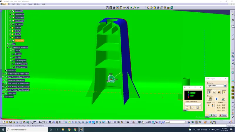
Main tooling axis for Doghouse Side Core clearance for doghouse interior
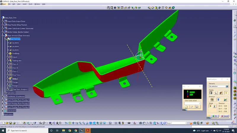
Draft analysis for flanges (Door Armrest)
Similarly, all other flanges are clear for the other parts.
Next up, push pins have to be placed on top of all 4 doghouses.
The push pins have been placed by assembly design using coincidence and surface constraints. The green coloured object is the push pin.
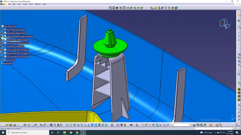
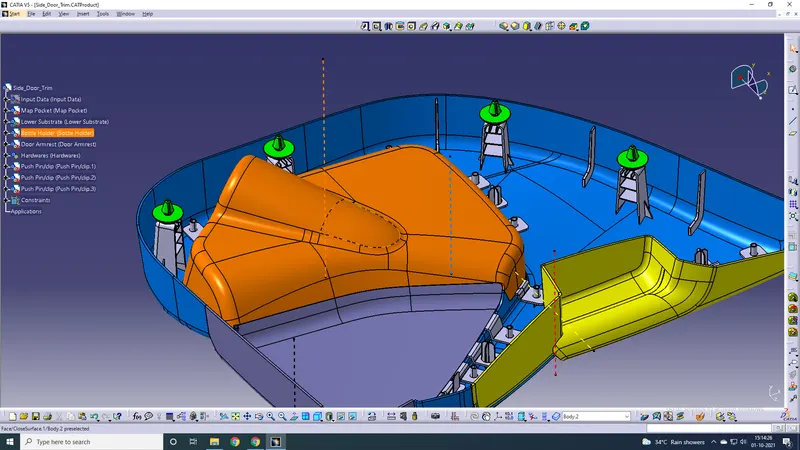
Push pins placed on all 4 doghouses
Hence, everything has been completed. The finished part is depicted below.
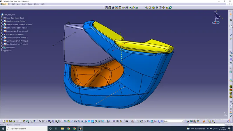
Front
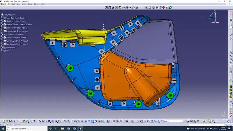
Rear
Conclusion: Hence the solid body of various parts of the door trim was made successfully with all necessary B-side features following all the design rules and guidelines.