Development of Car Door Trim
OBJECTIVE:
Development of a Door Trim panel
Creation of CAD model considering following inputs as like in OEM and tier1 companies
- a) Class A surface
- b) Nominal thickness: Refer to master sections
- c) Attachment strategy :
- Finding an attachment strategy for the door panel to complete work.
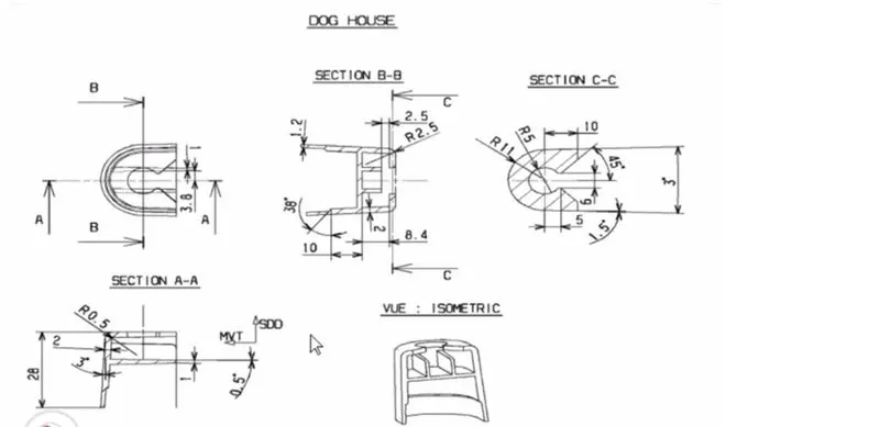
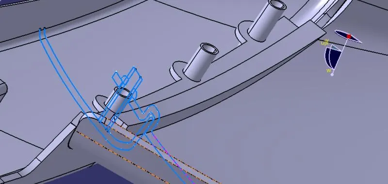
- Using Pushpin with Dog house for Lower substrate – Door panel attachment
- Using heat stakes for the part to part attachment
INTRODUCTION:
Door Trim panel
- Door panels serve as an interface between the interior of the car and the inner workings of the door, and between vehicle occupants and the door. They are expected to meet a variety of design specifications regarding safety, aesthetics, and functionality.
- In addition, they are expected to continue the material theme of the dashboard and pillars while concealing intricate electrical and mechanical components for operating locks, windows, and other features.
- The door panel has evolved from a simple two-part system of the latch and simple winding mechanism to a more sophisticated enclosure. Doors currently have an inner full-width panel consisting of electronic windows, a central locking system, and speakers. These panels typically consist of a foamed core covered with either textiles or plastics.
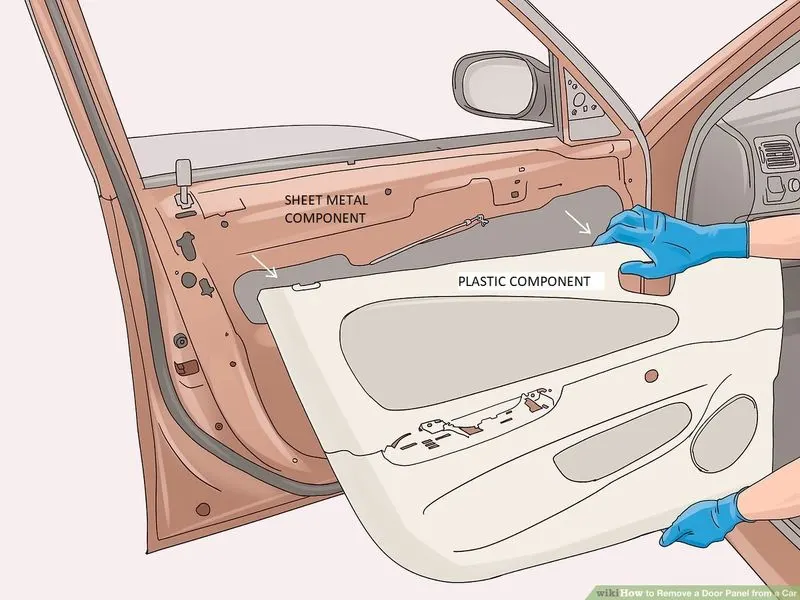
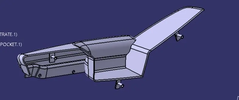
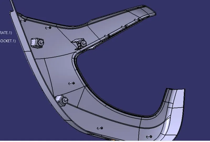
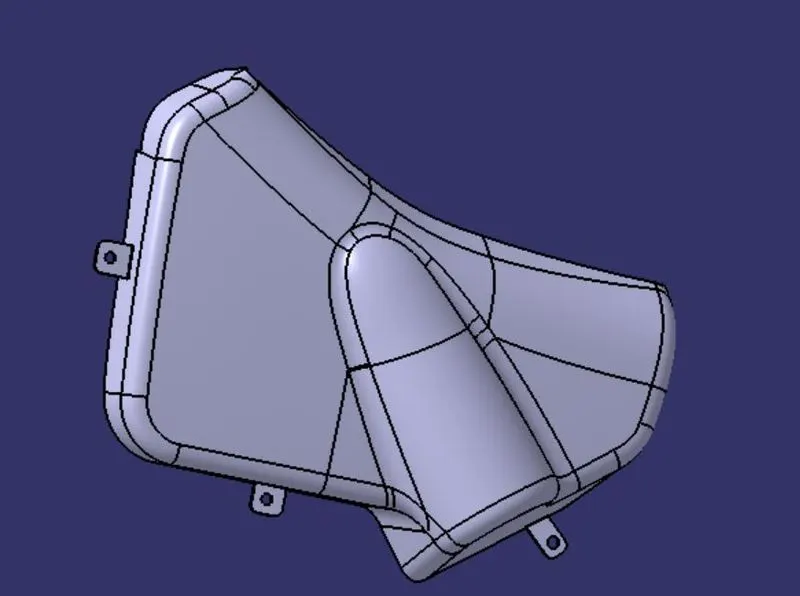
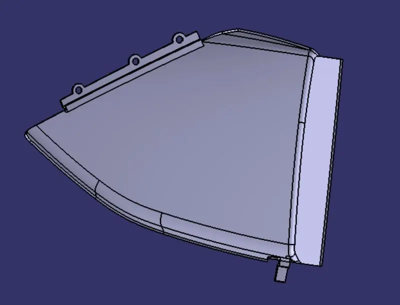
THE DOOR TRIM PANEL CONSISTS OF THE FOLLOWING COMPONENTS:
1.DOOR ARMREST
2.UPPER MAP POCKET
3.LOWER MAP POCKET
4.LOWER SUBSTRATE
5.UPPER SUBSTRATE
6.FLANGES
8.HEAT STAKES AND DOG HOUSE
Draft:
- A draft angle is a slant that is applied to each side of most features of an injection molded part. In other words Draft is providing tapers on the product features such as walls ribs posts and bosses that lie parallel to the direction of the release from the mold part ejection
- The nominal draft is 3mm for plastic components and for automotive sheet metal components is 7mm
Tooling axis :
- It is defined as the direction in which the molds opens or core and cavity, with the help of tooling axis created along x and Y axes are used for creating the Main Tooling axis by using the bisecting method
Master Section:
The master section helps us to decide the feasibility clearance, the packaging and the fixation strategy of a component before working in 3D. on the other hand master section gives us the thickness of the component
DOG HOUSES:
- Helps to avoid sink marks
- solves the length issues(ex: screw bosses can be formed at 100mm form B-surface)
- always design houses perpendicular to the tooling axis
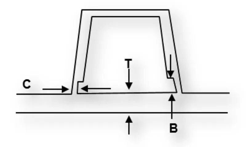
DOG HOUSE DESIGN CONSIDERATIONS:
- "C" is where the doghouse contacts the backside of the surface
- Doghouse wall thickness at the intersection of the part wall ( C ) should be 40% or less than the main wall stock ( T ).
- Height of ( B ) should be between 3.0 – 6.0 mm
CLASS A SURACE:
CLASS A refers to those surfaces which are VISIBLE and abide by the physical meaning, of a product. This classification is primarily used in the automotive and increasingly in consumer goods (toothbrushes, PalmPC's, mobile phones, washing machines, toilet lids, etc.).
CLASS A surfacing and its importance:
Class A surfaces are those aesthetic/ free form surfaces, which are visible to us (interior/exterior), having an optimal aesthetic shape and high surface quality. Mathematically class A surface are those surfaces which are curvature continuous while providing the simplest mathematical representation needed for the desired shape/form and does not have any undesirable waviness. Products are not only designed considering the functionality but special consideration is given to its form/aesthetics which can bring a desire in one’s mind to own that product. This is only possible with the high-class finish and good forms. This is the reason why in design industries Class A surfaces are given more importance.
In automotive design, a class A surface is any of a set of freeform surfaces of high efficiency and quality. Although strictly, it is nothing more than saying the surfaces have curvature and tangency alignment – to ideal aesthetical reflection quality, many people interpret class A surfaces to have G2 (or even G3) curvature continuity to one another (see free form surface modeling). Class A surfacing is done using computer-aided industrial design applications. Class A surface modelers are also called "digital sculptors" in the industry. Industrial designers develop their design styling through the Class A Surface, the physical surface the end-user can feel, touch, see, etc.
CLASS A SURFACE:
1.Visible surface and aesthetic look
2.surface with textures
3.Surfaces provided by customer(OEM)
4.Don't have any features like(rib, snap, bosses, etc) on class A surface.
5.Class A surface is made from scanned data with different software like alias etc.
6.Surfaces which is having CURVATURE CONTINUITY IS CALLED class-A
CLASS B SURFACE:
1.invisible Surfaces.
2.Surface mostly don't have textures
3.Surface needs to be created according to class-A surface.
4.having all features(Rib,boss,snap etc) in B-side surface only.
5.Surfaces which is having TANGENT CONTINUITY IS CALLED class-B
CLASS C SURFACE:
- Class C surfaces are the backside surfaces that can have tool marks, flash, and other imperfections without hurting appearance,
function, etc. - Class C surface is normally created using the sweep command.
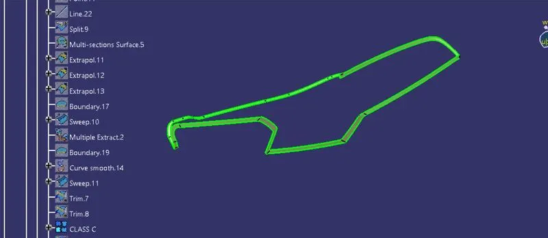
- First, the boundary is extracted and it is made smooth using the curve smooth command and then it is swept by giving 0.5 drafts outwards.
- Normally the C surface is nothing but adding thickness or filling the gap between the A surface and B
surface
PROCEDURE:
Connectivity of Class A surface:
The first and foremost thing to do is to check for the connectivity of the surfaces this is to ensure that there are no gaps between the surfaces if gaps are present then it should be resolved.
This can be done visually or by creating boundaries, if their gaps are present they are graphically represented by green lines. If not while performing boundary command it shows an error.
Creation of Dummy axis :
This is a normal line which we construct by analyzing the best possible direction(X/Y/Z axis) for the draft for the part, this axis is only for reference and is not used for Tooling Axis
Creation of Tooling Axis for Class A surface:
Taking the dummy axis as a reference, intersect the class A surface along the different axis (XY/YZ/ZX ) Check for the possible places where the part might face difficulties while ejecting the component from the mold.
Lines are drawn at the places where the part boundary has difficulties
Later the Tooling axis in one direction (let’s say X) is obtained by bisecting the lines drawn in the above process
In the same way, the other axis is also checked and then the Tooling axis in another direction(let’s say Y) is drawn
Now both Tooling axes are bisected and the final Tooling direction is obtained which is further used for all draft analysis axis and later unto developing Class C and Class B surfaces.
In this model, the tooling axis is taken from the Master sections provided, at the intersection of the Master sections
Publication:
The publication is used for easy access to published components. These will come in handy while modeling (we are not required to search the entire tree structure for a particular operation)
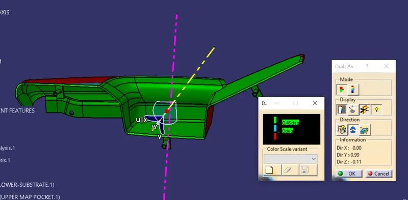
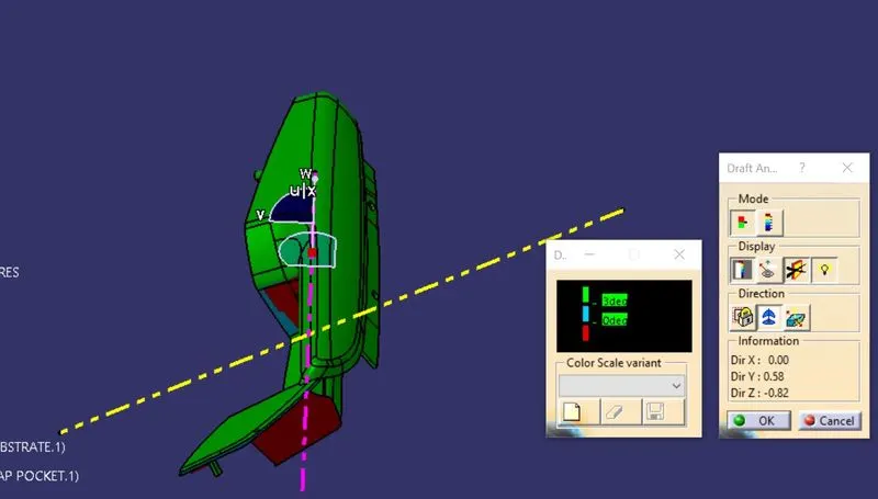
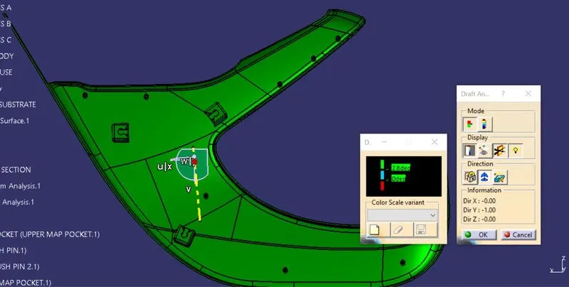
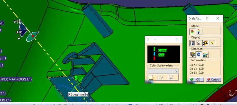
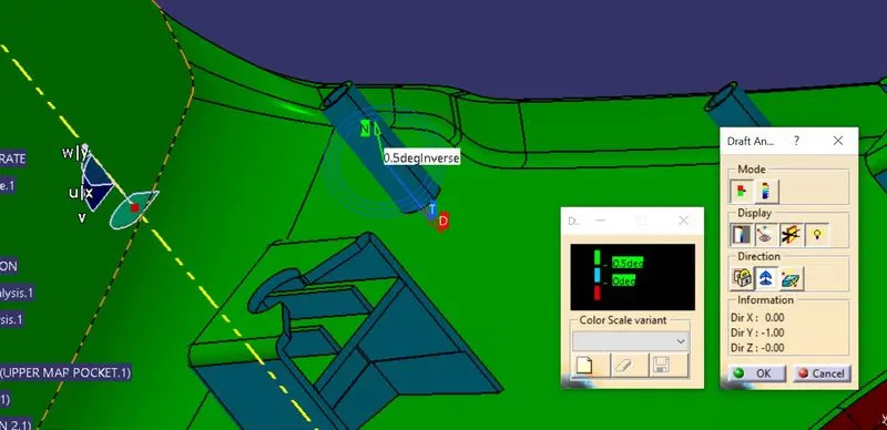
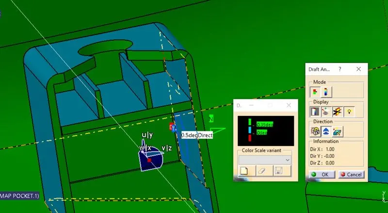
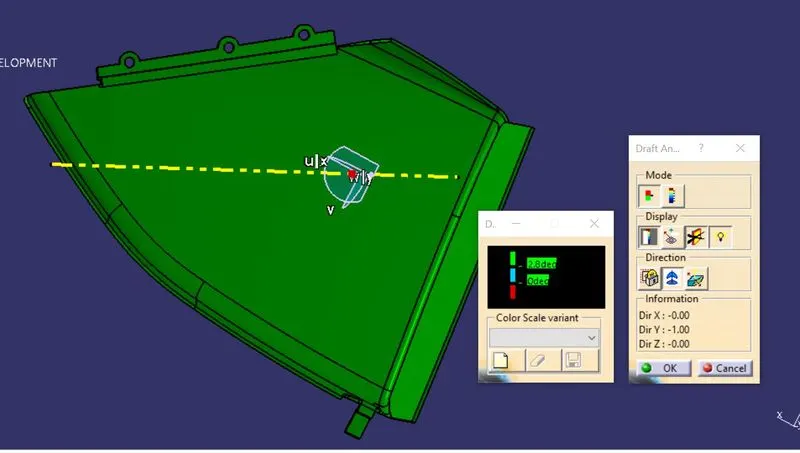
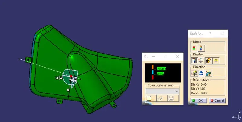
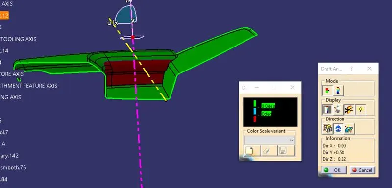
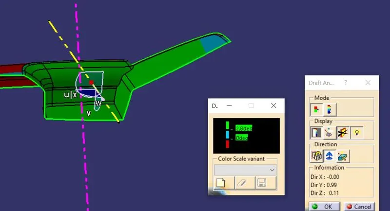
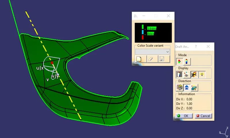
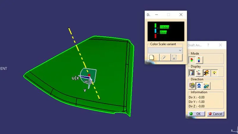
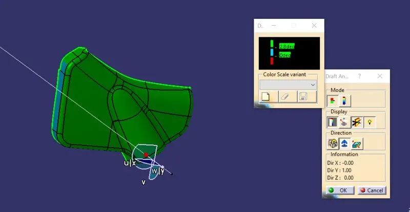
DRAFT ANALYSIS:
Click the Inset—Analysis -- (Feature) Draft Analysis icon
If material is not on There will be a warning message is shown and then we need to select the material
The Draft Analysis dialog box is displayed. It gives information on the display (color scale), the draft direction, and the direction values
DEVELOPMENT OF CLASS B SURFACE:
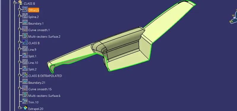
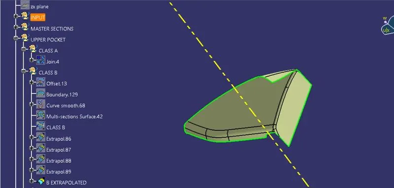
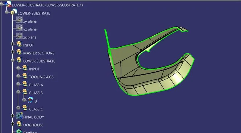
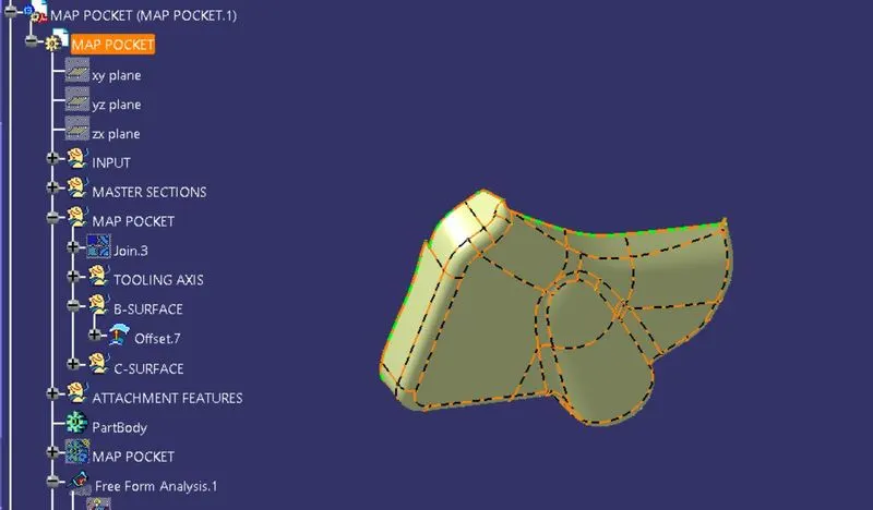
Class B surface is created by extracting each wall and untrimmed walls extrapolating the walls and then trimming the extra surfaces and offsetting it to a certain value based upon the thickness of the component which is obtained from the master section. The offset surface will be the B-Surface
DEVELOPMENT OF CLASS C SURFACE :
This surface is obtained by sweeping the boundaries of the Class A surface along the Tooling Axis direction, it connects A and B surfaces
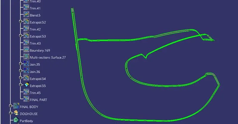
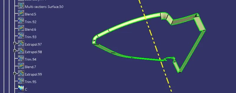
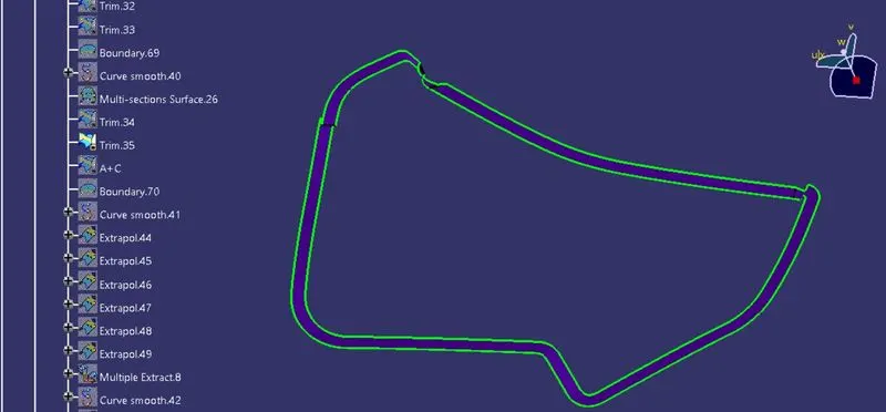
Using A+C surfaces and trimming with B-Surface a closed surface
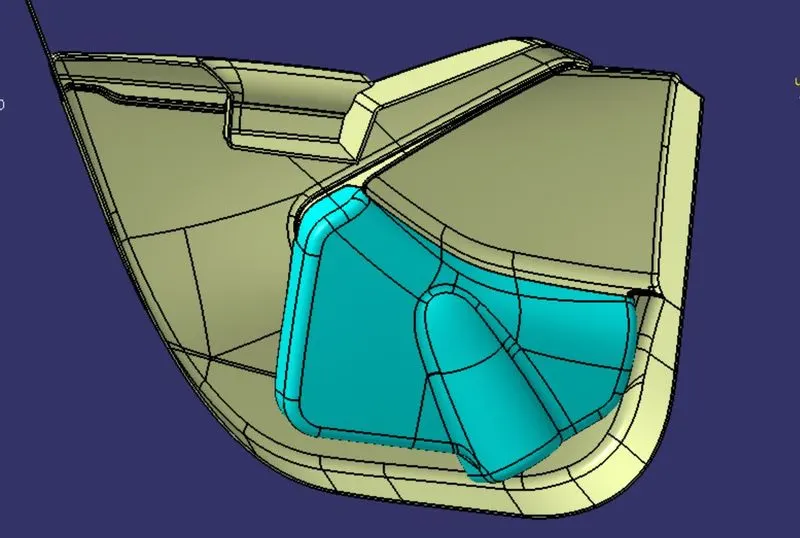
The Final trim part is converted into a solid component using closed surface command
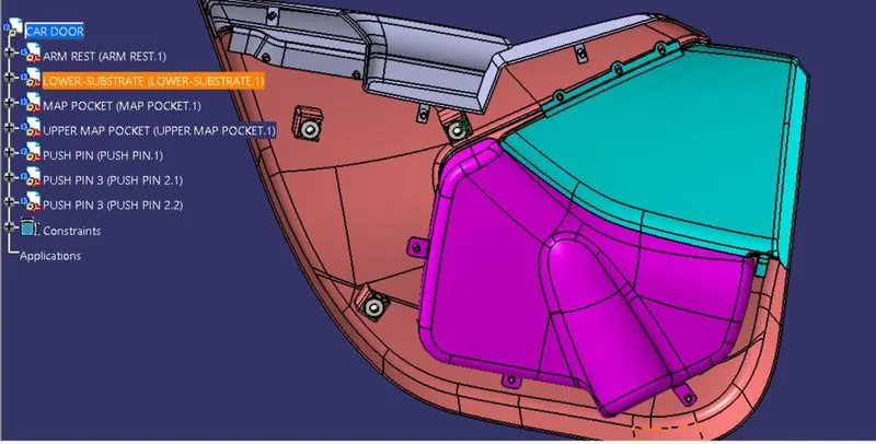
MASTER SECTIONS AND THEIR GEOMETRIES CREATION:
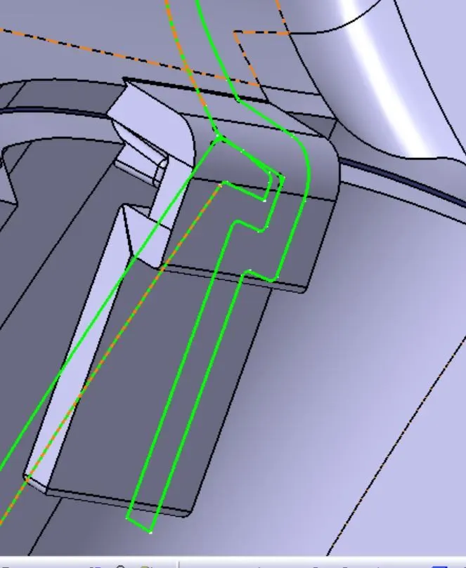
Follow master section to develop the flanges and all attatchment features
the given master sections are not appropriate hence the dimensions for heat stakes are taken from previous exercises
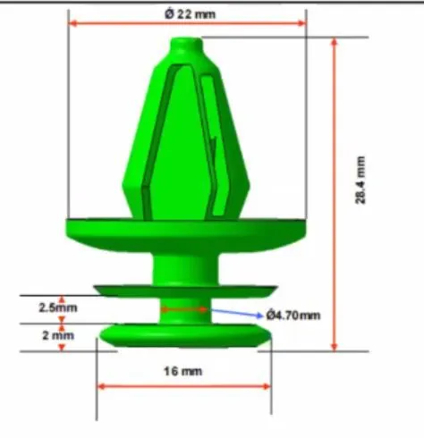 PUSHPIN DIMENSIONS
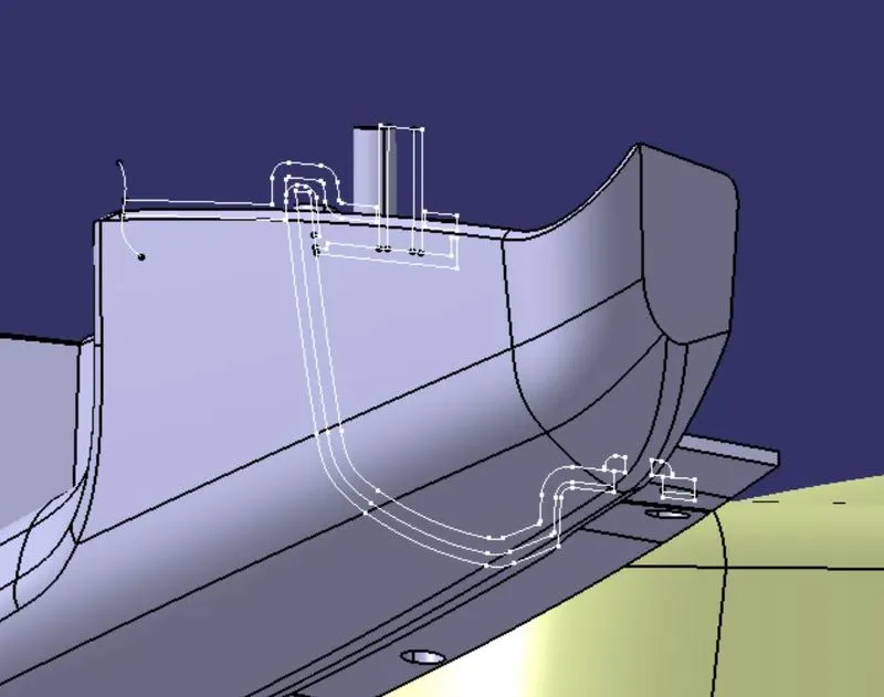
DRAFT ANALYSIS OF CLOSED SURFACE MODEL: