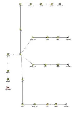
Week-11 : Discretization of 3D intake manifold using GEM-3D
AIM:
To Explotre Tutorial- single cyl DI
To Explore tutorial no 2 (GEM3D) - “Building intake manifold from STL model”
Theoritical Background:
Discretization
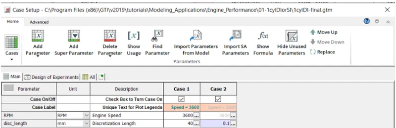
Discretization is the process of converting Physical volume in to number of Sub volumes. Discretization splits the larger parts in to smaller sections in order to improve model accuracy. The Discretization length will affect the computational time in a different way for each solution method. Discretization length affects the Time step when the explicit flow solver is used. The less discretization length, more time is consumed to solve the number of equations due to more number of cells. The Computational time will be higher for small discretization lengths because there will be more sub volumes in the system which requires calculation of temperature and pressure, that is there are more solution variables.
In case of Engine Cycle simulation where explicit solution methods are used
1] A disretization length of 0.4 times the cylinder bore is recommended for the intake system and 0.55 times the cylinder bore is recommended for the exhaust system.
2] The discretization length should decrease for any simulation that will require high frequency analysis such as engine performance above 6000 rpm.
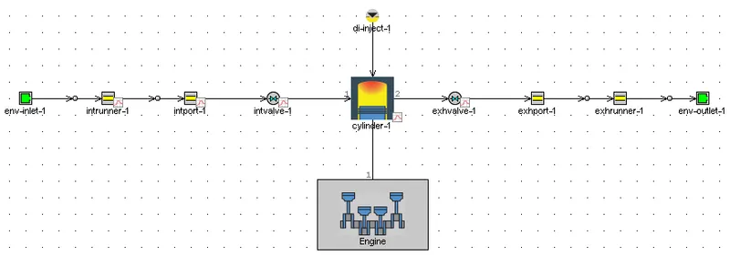
To Explotre Tutorial- single cyl DI
CI engine has high compression ratio and large amount of air to fuel ratio. In CI engine air is let in to the engine cylinder and compressed in to very high pressure.
Case Setup:
Results:
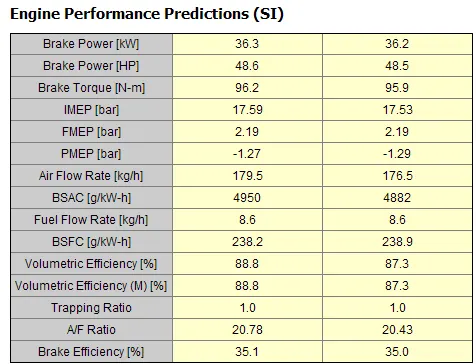
Key Cylinder Predictions

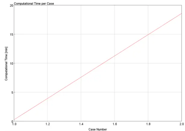
Computational Time:
To Explore tutorial no 2 (GEM3D) - “Building intake manifold from STL model”
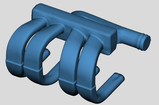
Steps to convert 3D Intake manifold using Gem 3D to 1D GT Model
Step 1:
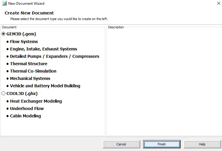
Select Gem3D and create a new model by selecting new file
Step 2:
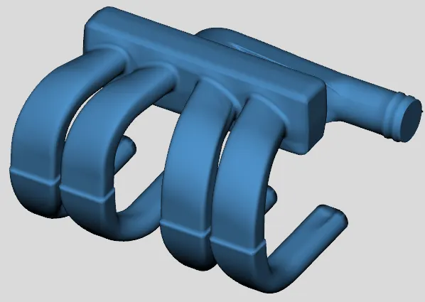
We have to import the Intake Manifold from an STL File that is provided in the GT Installation. Navigate to Nonlinear_(standard) directory and select Plenum.stl file. We have to make sure 'Surface' option is selected before importing the model.
Step 3:
Go to convert tab and select separate by curves. This will separate the geometry in parts based on the changes in the surface of the object. The intake and the 4 intake runners are closed. Set tolerance limit to 1. The process will separate the intake runners in to 2 different sections.
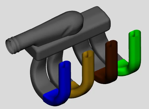
Step 4:
The runners has to be separated from the manifold as the runner can be represented by pipes. Select 3 point cutting plane and choose 3 points on the underside of the manifold. We have to translate the cutting plane and set it at an appropriate position. We have to make sure that only runners has to be cut and not the surface of the manifold.
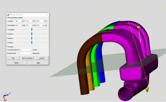
Step 5:
Once we have sections that can be represented by pipes or flowsplits we need to convert them into flow components. This is done with the convert mesh operation. Select Runner Pipe and choose "Convert Shape to Component" option. Select the geometry type we would like to convert. Assign port number. Keep an appropriate dimension of the pipe and keep it fixed until the end of the pipe. We do it for all the runner ports.
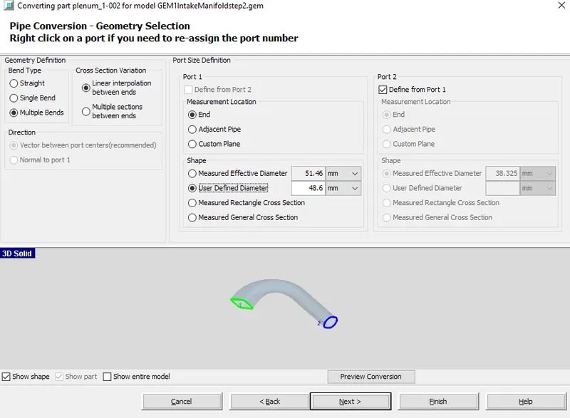
Step 6:
We need to add orifice connection to represent the information regarding the curved entry from the manifold. While giving the orifice connection between manifold and runner set discharge coefficient as parameter
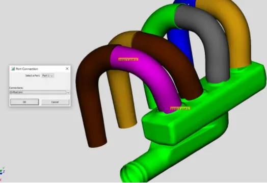
Step 7:
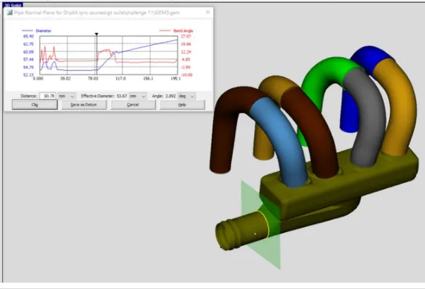
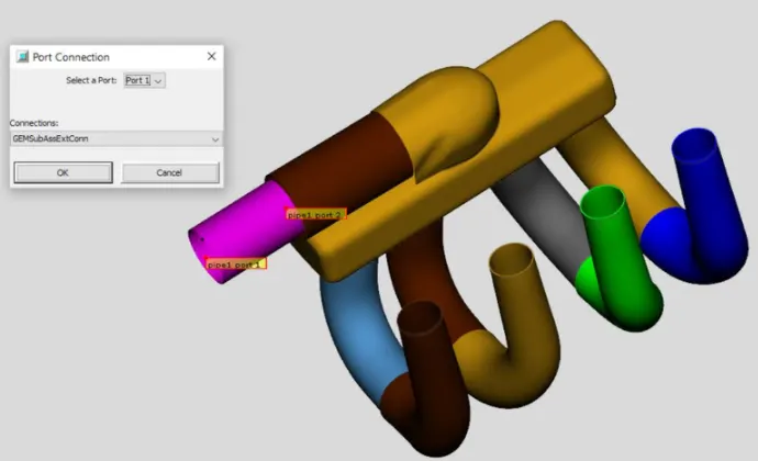
Select the entrance manifold these sections can be converted in to 2 pipes. The entrance appears as the pipe section with round and D shape. The straight section can be converted in to pipe. Select "Pipe Normal Cutting Plane" from the convert tab. The plane cab be translated as far as there is no abrupt change in the dimension. We have to specify the end connecitons. In the model ends of each connection, needs an end connection specified. This is done with the help of Subassembly connection.
Step 8:
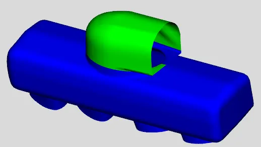
The cutting plane is rotated and adjusted in a way such that it does not cut the manifold plenum. The cut model is as shown below
Step 9:
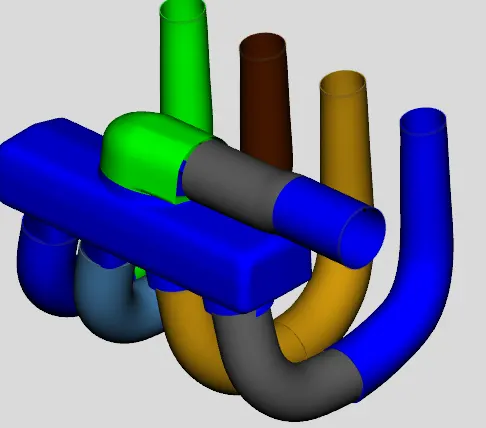
Dividing the pipe section with area changes
Step 10:
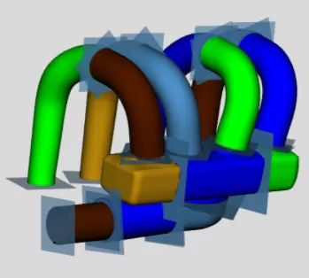
The entire section is converted in to Flow split
Step 11:
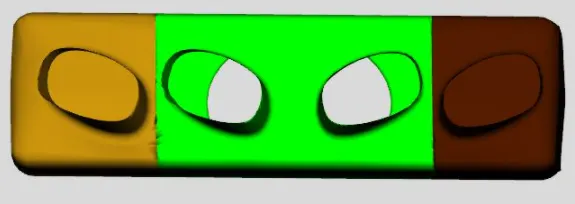
After cutting pipe there is a gap between pipe and the manifold. To fill this gap we have to select flow connection
Step 12:
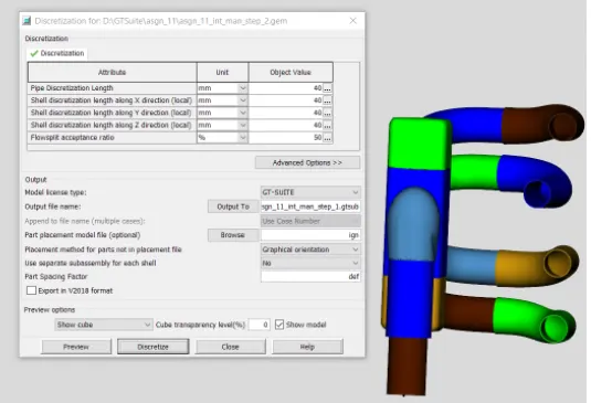
To discretize the model select the model in proper orientation
Step 13:
The discretized model is as shown below