Week-11 Challenge: Braking
OBJECTIVE:
- To calculate the energy required for braking for the defined driving cycle.
- At high speed Why electric motor can’t develop braking torque similar to starting and to determine How electric and mechanical brakes are coordinated.
- To make a MATLAB program that plots contour of given motor speed, torque, and efficiency values.
PROCEDURE:
1)Energy Required in Braking:
- The driving cycle is generated in an Excel worksheet.
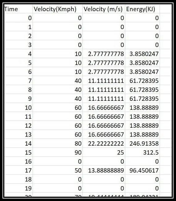
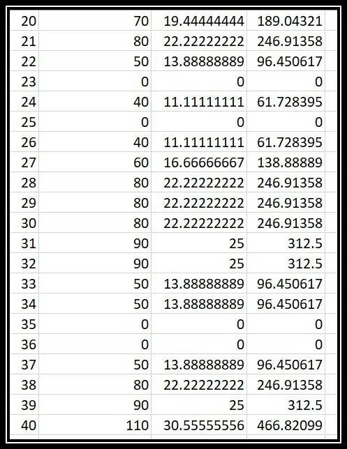
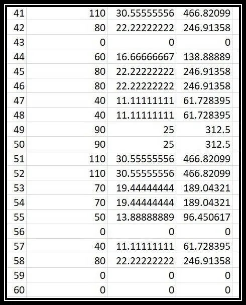
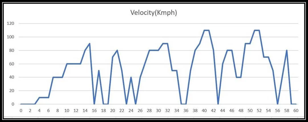
- At each point, the kinetic energy`1/2(mv^2)` where m is the mass(kg) and v is the velocity in(m/s) is calculated.
- During deceleration only, the brakes will be applied, so consider only those points and the kinetic energy is calculated.
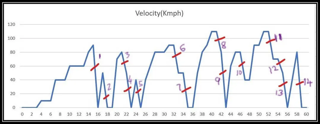
- Then the total braking energy is calculated by the summation of all the braking energy spent on each deceleration point.
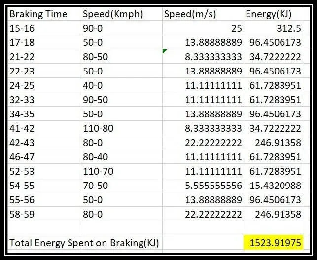
- From the above calculation, we found that the total energy spent on braking is 1523.92KJ for this driving cycle we created.
2)At high speed the electric motor can’t develop braking torque similar to starting:
When the motor is at rest it has to operate from a standstill position to reach the moderate speed, high torque is required in order to bring the motor in motion. Whereas while braking, the motor is already operating at high speed, the maximum operating limit is already reached by the motor operation and thus further higher torque could not be obtained while braking. The braking operation happens in the motion which is been distributed as per proportion in the brake energy and the regenerative braking.
BRAKING:
The term braking comes from the term brake. We know that brake is equipment to reduce the speed of any moving or rotating equipment, like vehicles, locomotives. The process of applying brakes can be termed as braking. We can classify the term braking into two parts:
- Mechanical Braking
- Electrical Braking
MECHANICAL BRAKING:
The mechanical braking which we usually see and experience in all vehicles the brake pedal in the vehicle cabin helps us to engage or disengage the brakes. Currently, the braking technology has done wonders by inventing life-saving braking technologies such as ABS, EBD, BA, and many. In all these vehicles when the driver applies the brake, the brake pad comes closer to the disc connected with the driving disc. The brake pads usually inefficient braking in long term due to its wear.
ELECTRICAL BRAKING:
The main idea in electrical braking is to change the direction of the flux. Brakes are used to reduce the speed of motors. We know that there are various types of motors available (DC motors, Induction motors, Synchronous motors, SIngle phase motors, etc.) and the specialty and properties of these motors are different from each other, hence these braking methods also differ from each other. The braking can be divided into three parts mainly which include:
- Regenerative Braking.
- Plugging type Braking.
- Dynamic Braking.
Regenerative Braking:
Regenerative Braking takes place whenever the speed of the motor exceeds the synchronous speed. This braking method is called regenerative braking because here the motor works as a generator and supply itself is given power from the load, i.e.motors.The main criteria for regenerative braking are that the rotor has to rotate at a speed higher than synchronous speed, only then the motor will act as a generator and the direction of current flow through the circuit and direction of the torque reverses and braking takes place. The only disadvantage of this type of braking is that the motor has to run at a super synchronous speed which may damage the motor mechanically and electrically, but regenerative braking can be done at a subsynchronous speed if the variable frequency source is available.
Plugging Type Braking:
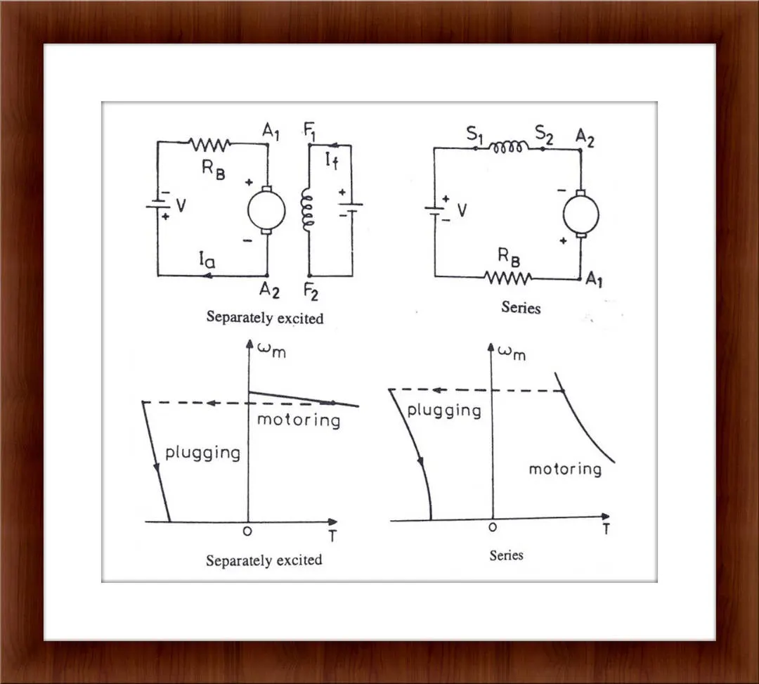
In this method, the terminals of the supply are reversed, as a result, the generator torque also reverses which resists the normal rotation of the motor, and as a result, the speed decreases. During plugging external resistance is also introduced into the circuit to limit the flowing current. The main disadvantage of this method is that here power is wasted.
Dynamic Braking:
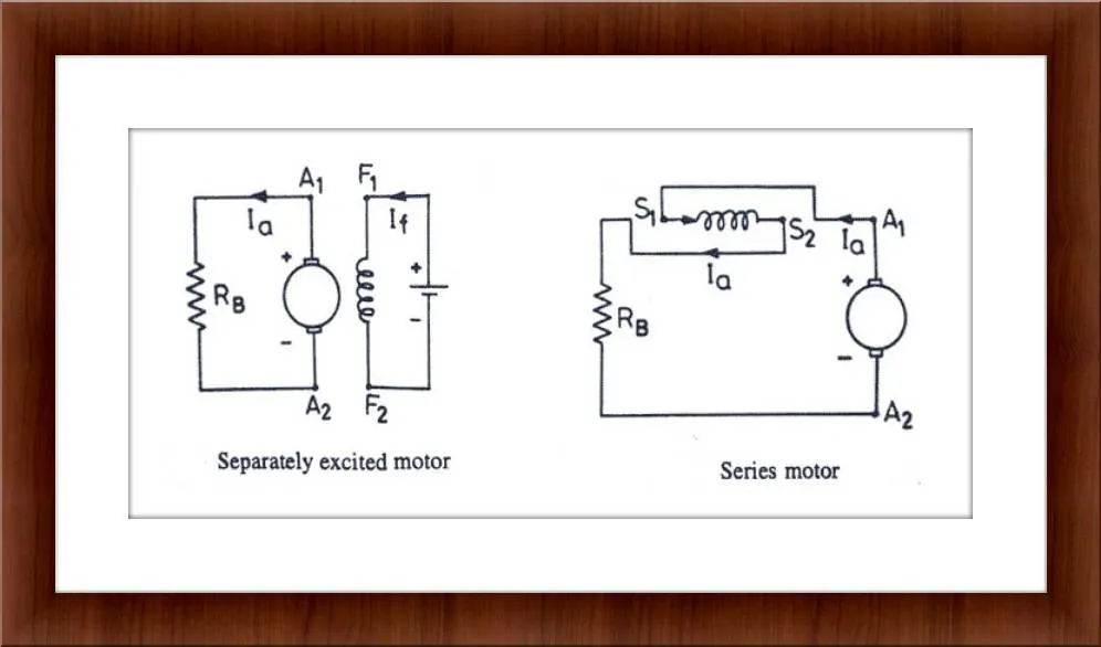
In this method, the direction of the torque is reversed and braking is applied. In this method of braking the motor which is at a running condition is disconnected from the source and connected across a resistance. when the motor is disconnected from the source, the rotor keeps rotating due to inertia and it works as a self-excited generator. when the motor works as a generator the flow of current and torque reverses. During braking to maintain the steady torque sectional resistances are cut out one by one.
Electrical and Mechanical braking systems are coordinated by using the Brake strategy subsystem:
- Series Braking technique.
- Parallel Braking technique.
Series Braking Technique:
When the brake pedal is pressed and depends on the level of depression, brake torque is sent. Now, this brake torque passes into the brake control strategy block. If the battery state of charge is below 80% which is set as the maximum permissible level of charge. If that condition is satisfied, then the battery is recharged. The brake torque requested is compared to the maximum regenerative torque limit of the motor-generator. If the overall brake torque requested is less than or equal to the maximum regenerative torque, then the vehicle brakes purely on regenerative torque, and the battery is charged. The amount of charge depends on the motor-generator operation efficiency and the battery charging efficiency. If the overall brake torque requested is greater than what the motor-generator can provide, then the friction brakes kick in. Since the vehicle is front-driven, it is checked if the total brake torque requested from the front is less than or equal to the maximum regenerative torque capability of the motor-generator. If yes, then front braking is provided purely by regeneration and rear by friction. Once the total brake torque request increases, then front friction brakes come into play in combination with rear friction brakes and front regenerative braking, to satisfy the overall brake torque demand.
Parallel Braking Technique:
Once the brake pedal is applied and a desired overall brake torque request is sent from the driver block. This braking torque on passing through the brake control strategy gets divided between regeneration and friction braking at all times. As parallel regenerative braking is add on to the conventional systems, it is devoid of any integrated control. So to make the transition and co performance of regenerative braking with friction smooth, it is assigned in such a way that, there is a clear division between the amount of brake torque that will be achieved from regeneration and friction braking. On the application of brakes and in keeping with the design of the motor-generator, it is designed to operate as a generator in a constant torque operator region. A motor-generator can provide a maximum of 322N-m of the generator at or under base speed. The generator is scaled such that the base speed of the generator corresponds to a velocity of 124Kmph which is the maximum speed limit on most highways. Hence regeneration works as long as the vehicle is braking from a speed of under 124 Kmph and the requested brake torque on the front-driven wheels after the front-rear brake split is greater than or equal to maximum generator torque. If that condition is satisfied, then the regenerative braking and friction braking operates in tandem else it's just the friction brakes at the driven and the non driven axle.
3)Contour plot:
clear all
close all
clc

x=linspace(1,1000);%speed in rad/s
y=linspace(1,250);%torque in N-m
kc=0.2;%For copper loss
ki=0.008;%For iron loss
kw=0.00001;%For windage loss
conl=20;%For constant motor loss
[x,y]=meshgrid(x,y);
output_power=(x.*y);%power=speed*Torque
B=(y.^2)*kc;%copper loss
C=x*ki;%iron loss
D=(x.^3)*kw;%windage loss
input_power=output_power+B+C+D+conl;
z=output_power./input_power;
%Now set the efficiencies for which the contour to be plotted.
V=[0.65,0.70,0.75,0.80,0.85,0.90,0.92,0.94,0.95];
box off
grid off
contour(x,y,z,V);
xlabel('Speed(rad/sec)')
ylabel('Torque(N-m)')
Step-Wise Explanation:
- The speed in rad/s and the torque in N-m are defined using the linspace command.
- Then, the copper loss constant, Iron loss constant, the windage loss constant, and the constant loss is assumed.
- In order to plot the contour, we convert the 1-D array into a 2-D array by using the mesh grid command.
- Then the output power is calculated.
- Then the copper loss, iron loss, and windage loss are calculated.
- Then the input power is calculated which is the summation of all the losses.
- Then the efficiency is calculated using the formula.
- The efficiency values are set for which the contour to be plotted.
- Using the contour command, the plot is generated for the speed, torque, and efficiency.
- Then in the next step, the x-label and y-label are given.
RESULT:
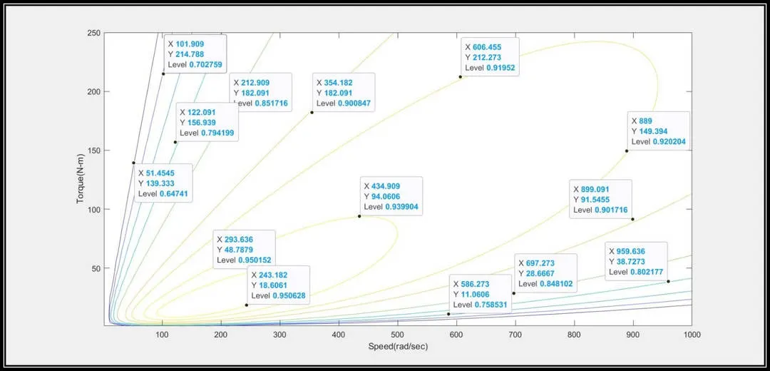
- This the plot which is observed for various efficiency values as mentioned in the program.