Week 11 Challenge
1. Friction load determination
Q-1 : A pipe carrying LNG rests on the shoe having vertical force of 125 kN. Calculate the Friction load on the axis. Also find the friction force, if TEFLON pad is used between shoe and pipe support.
AIM & INTRODUCTION : A pipe carrying LNG rests on the shoe having vertical force of 125 kN. Friction load on the axis and friction force are required to be determined if there is TEFLON pad between shoe and pipe support.
PROCEDURE IN DETAILS :
Friction factor/coefficient and friction load on piping-
| Materials | Friction factor |
| Steel to Steel | 0.3 |
| Teflon to Steel | 0.1 |
(A) When Steel pipe is resting on steel:
Friction force in longitudinal direction (Ff��) = Coeff of frictionx Gravity Load
= 0.3x125 KN = 37.5 KN
Friction load in transverse direction = 10% of piping operatin load
= 0.1x 125 = 12.5 KN
RESULT : Friction load in longitudinal and Transverse direction are 37.5 KN & 12.5 KN respectively when pipe is resting on steel and these friction forces are 12.5 KN & 12.5 KN respectively when pipe is resting on Teflon.
(B) When Steel pipe is resting on Teflon :
Friction force in longitudinal direction (Ff��) = Coeff of frictionx Gravity Load
= 0.1x125 KN = 12.5 KN
Friction load in transverse direction = 10% of piping operatin load
= 0.1x 125 = 12.5 KN
2. Support Types
Q- 2 : Identify the type of support as Spring, Guyed, Stop or Semi Anchor (Guyed + Rest + Stop ) or Rigid Strut from following images.
AIM & INTRODUCTION : Identify the type of support such as Spring, Guyed, Stop or Semi Anchor ( Guyed+ Rest+ Stop) or Rigid Strut from the given images .
PROCEDURE IN DETAILS :
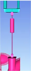
Fig-1
Image in Fig-1 above has Spring Support which permtt the pipe to move in vertical direction
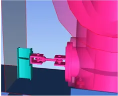 I
I
Fig-2
mage in Fig-2 has RIGID Support which allow small angular displacement and thermal movement.
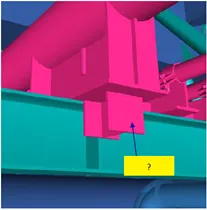
Fig-3
Image in Fig-3 has Stop support which restrained the movement of pipe in axial direction but allows the pipe movement in lateral direction
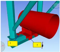
Fig-4
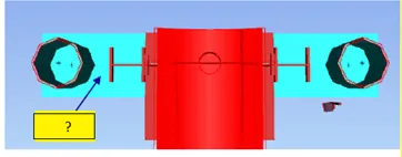
Image in Fig-4 above has Semi Anchor Support which restrict the pipes to move in axial as well as transverse direction.
 I
I
Fig-5
Image in Fig-5 above has Guid support which restrained the lateral movement in two direction therefore also limits the rotational movemement of pipe but permitt axial movement of pipe
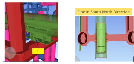
Fig-6
Image in fig-6 is associated with Anchor Support which does not permitt the pipe to move in any direction thus movement in all 6 degree of freedom is restricted.
RESULT : As explained above it is concluded that different figures are associated with diifferent support depending upon the requirment to restrict movement and absorb the stresses.
Q-3: Design of a pipe rack
Design a typical pipe rack bent in oil plant. The pipe rack configuration shall be as shown in Figure 1 and the plan layout as shown in Figure 2.
AIM & INTRODUCTION : Model of pipe rack bent in oil plant is to be prepared from the given inputs and figures. Following are some given inputs-
Height of Column = 9 m
Height of First tier = 6 m
Height of Second tier = 7.5 m
Height of Third tier = 9 m
Width of Pipe Rack = 7.5 m ( C/C of Column in width of pipe rack)
Span of each Bay = 6 m
Number of bays = 7
Top tier of pipe rack has 3 nos cable trays each 150 mm wide
Second tier of pipe rack has 4 pipes ,one of 24 " dia and one of 12 " dia, remaining two pipes are of dia 8"
First tier of pipe rack has 6 pipes ,one of 18 " dia and remaining 5 pipes are of dia smaller than 8"
PROCEDURE IN DETAILS :
Folloing Loads are to be assigned-
1- Structural Dead Load :
Load due to weight of Structure excluding weight of pipe
2-Operating Dead Load :
Weight of pipe, fluid in it and insulation. UDL of 1.9 KN/Sqm is asuumed for pipe of dia 8". Point load is considered at appropriate location for pipe larger than 8" dia pipes which will be reported by Piping Engineer.
3-Empty Dead Load :
Weight of empty pipe without fluid in it but including insulation , it is assumed as 60% of operating load
4-Test Dead Load :
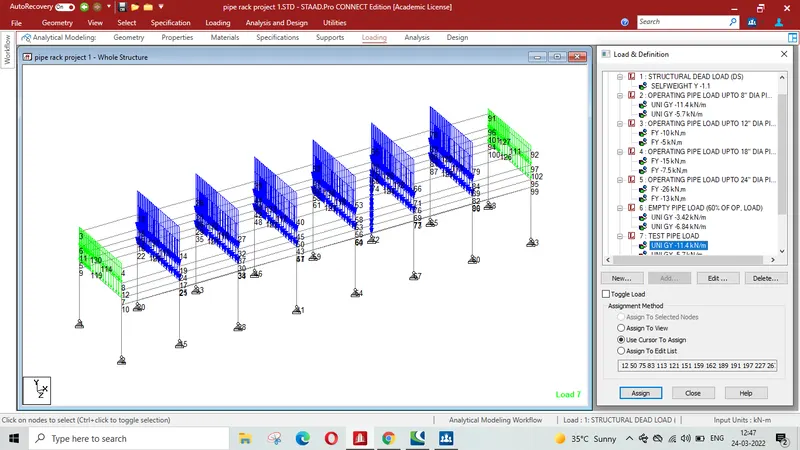
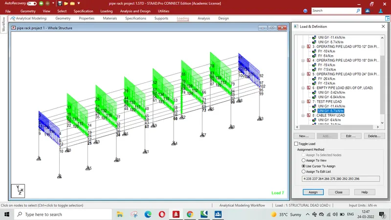
In case test medium in pipe is not known, water with density of 1000Kg/CuM is considered as test medium so generally test load is same as operating dead load.
5- Cable Tray Load:
UDL of 1 KN/m is considered
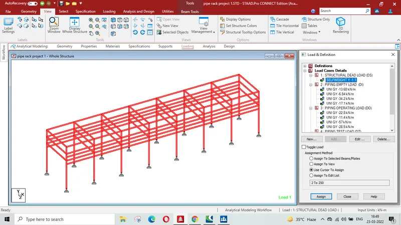
Print Screen showing Structural Dead Load.
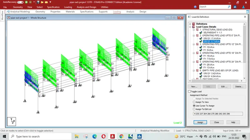
PRINT SCREEN OF PIPING OPERATION LOAD ON 1st & 2ND Tier for pipe of dia upto 8""-
Load calculation- 1.9 KN/Sqm x 6 m bay length = 11.4 KN/m
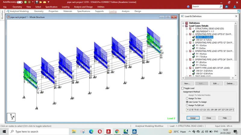
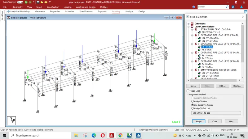
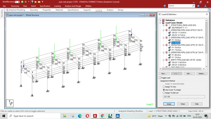
PRINT SCREEN OF PIPING OPERATION LOAD ON 1st & 2ND Tier for pipe of dia 12" of End Bay & Intervenning Bays of 2nd Tier-
PRINT SCREEN OF PIPING OPERATION LOAD ON 1st Tier for pipe of dia 24" of End Bay & Intervenning Bays of 2nd Tier-
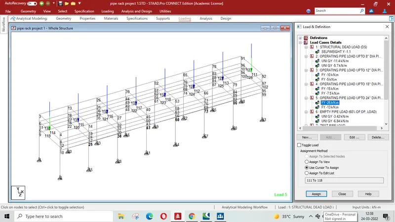
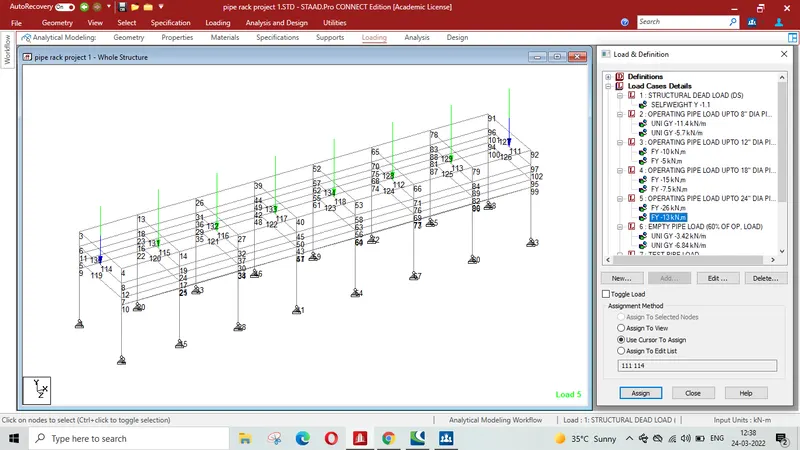
PRINT SCREEN OF PIPING OPERATION LOAD ON 1st Tier for pipe of dia 18" of End Bay & Intervenning Bays -
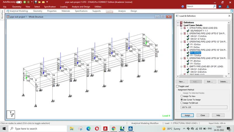
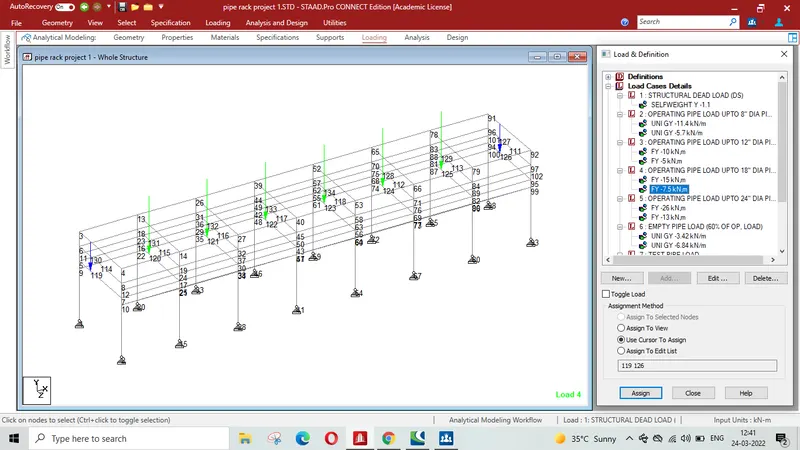
Empty Dead load of pipe ( 60% of operation load of piping)
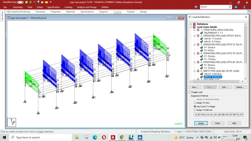
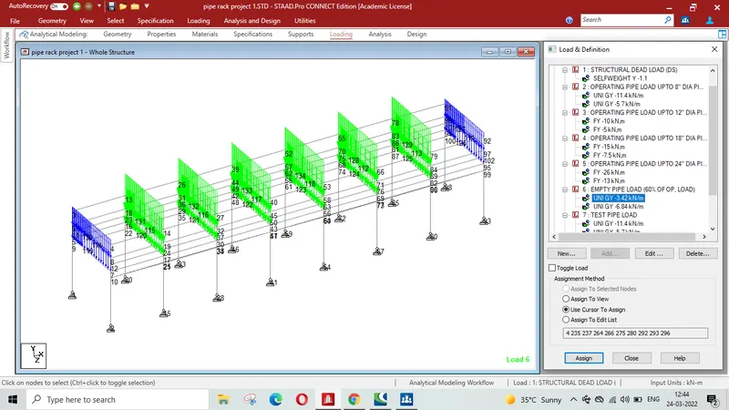
PRINT SCREEN OF TEST PIPE LOAD ( same as piping operation load) -
RESULT -
Pipe Rack as per given plan and Elevation has been modelled using STAAD PRO software and various members have been assigned the properties. Various Load due to piping in different situation such as empty pipe case when Siesmic effect is considered, operational pipe load when the pipe rack is commisioned i.e. fluid is being transported throuh it including insulation ( UDL @ 1.9 KN/Sqm for pipe upto 8" dia and Point load due to pipe of dia larger than 8" which will be prvided by piping engineer, however in the given challenge only profile of various has been indicated) , Test load will be considered with pipe load full of test fluid ( shall be considered water as test fluid if not known ), Cable tray load is considered @ 1 KN/Sqm on top tier of pipe rack. Load in various cases have been shown through Print Screen whch are attached.