Week 11 Car Crash simulation
AIM
- To perform the parametric study for 3 different values of thickness for the car body.
OBJECTIVE
- The video is provided for the car crash simulation for boundary condition and simulation setup, need to perform the parametric study using three different values of thickness for the car body in the explicit Analysis.
INTRODUCTION :
- A Crash Simulation is a virtual recreation of a destructive crash test of a car or a highway guard rail system using a computer simulation in order to examine the level of safety of the car and its occupants. Crash simulations are used by automakers during computer-aided engineering (CAE) analysis for crashworthiness in the computer-aided design (CAD) process of modeling new cars. During a car simulation, the kinetic energy or energy of motion, that a vehicle has before the impact is transformed into deformation energy mostly by plastic deformation (Plasticity) of the car body material (Body in white) at the end of the impact.
Types of testing preferred :
- Frontal Impact Test
- Side Impact Test
- Rear Impact Test
PROCEDURE
Setups - Geometry
- Importing the geometry into the SpaceClaim to check the car and wall geometry surface and their any irregularities between surfaces that need to be fixed but the geometry is fine to set up the boundary conditions.
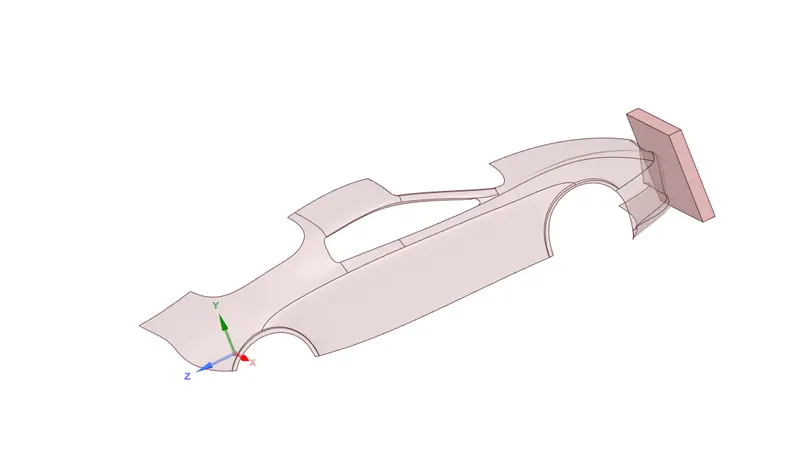
- Rename each part of the body as a there Car body, Wall, and other two parts that are not visible that need to be suppressed, For the wall using structural steel as the material and for the car body stainless steel with a thickness of 0.4 0.3 and 0.2 setting up the parameters for different values.
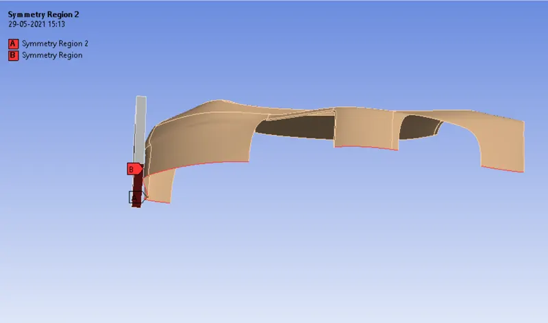
Symmetry
- Adding up the two symmetry region to the geometry symmetry region 1 for that car body part by selecting the edge interface and adding 12 edges of the car body.
- Second symmetry region one side of the face of the wall.
Mesh
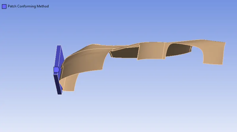
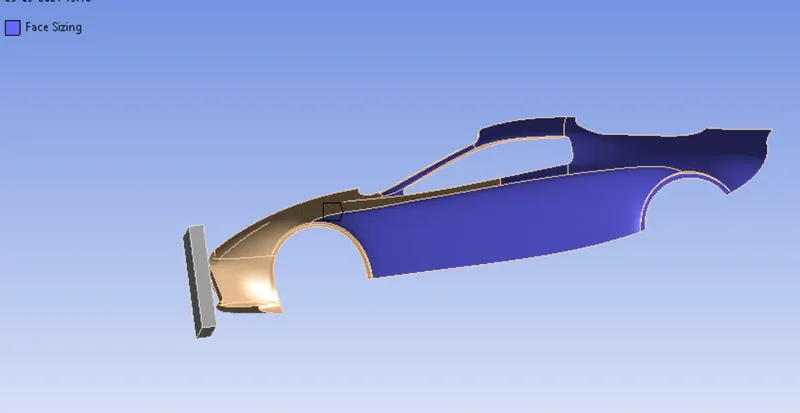
- Using patch conforming method for the wall, as selecting whole body size and with the elements as tetrahedrons. But for the car body selecting the filter as the face sizing with the size of the element as default to the selected car body.
All Triangles Method :
- Select the whole car body surface, change into "Triangular" instead of "Quadrilateral Dominant" and then click to proceed for meshing.
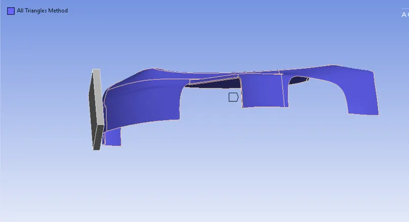
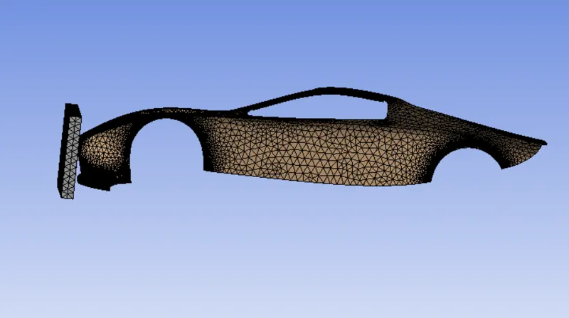
- Default mesh is generated with a total no of nodes are 25911 and elements as 27987 which is below the academic limit.
Analysis settings
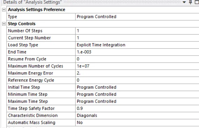
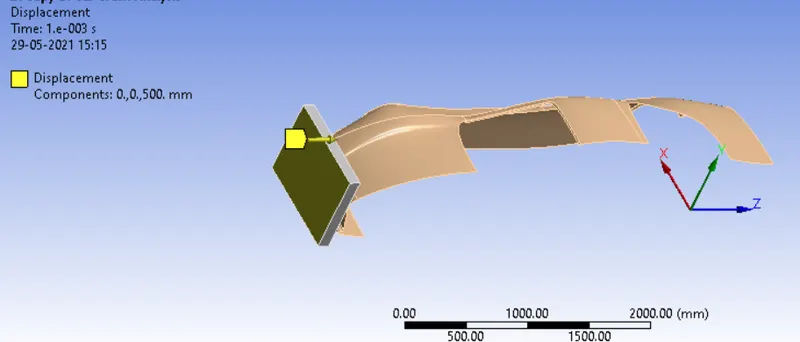
- Setting up the analysis for the simulation purpose giving value to the end time (1 e-003) and other settings to be same.
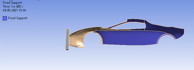
- Adding fixed support to the body by selecting the 6 faces of the body which will not in contact with the wall body while crashing between them.
- Selecting the side face of the wall by giving the displacement 500 mm to the z-axis and time as the (1 e-003).
RESULTS
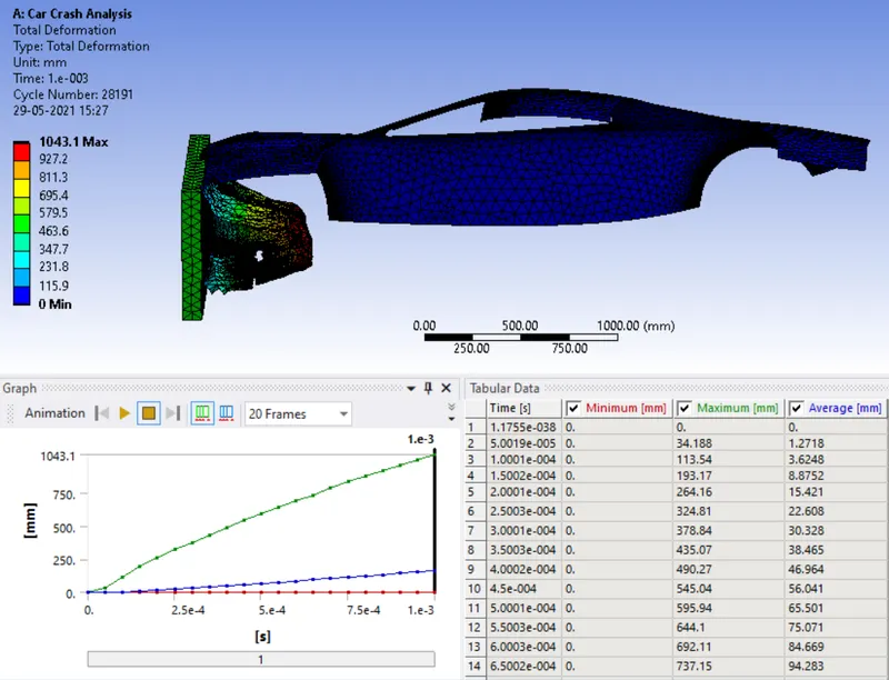
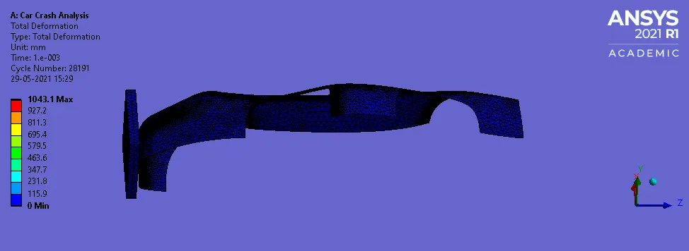
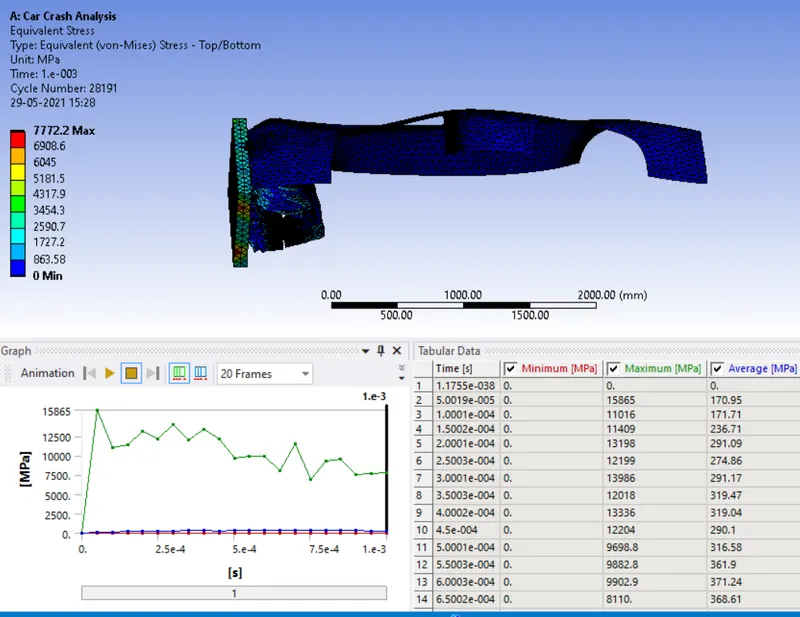
Case 1: Parametric Value of 0.3mm
Total deformation
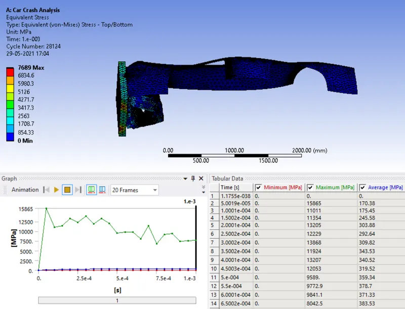
Equivalent von mises stress
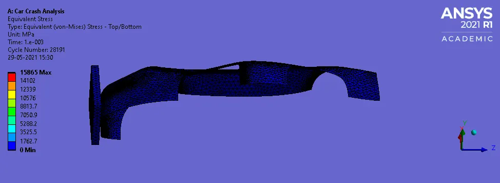
Case 2: Parametric Value of 0.6mm
Total deformation
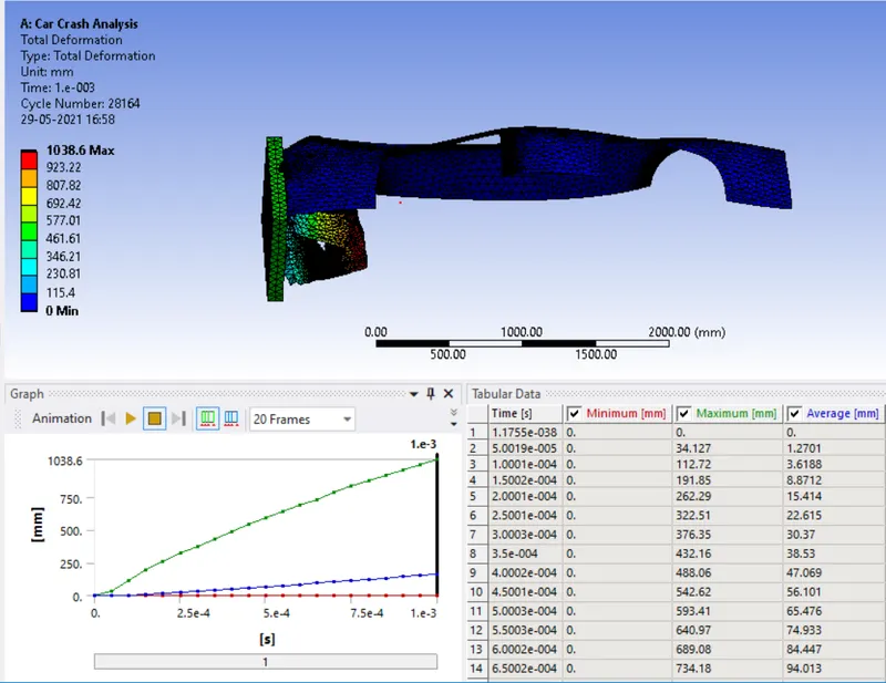
Equivalent Stress :
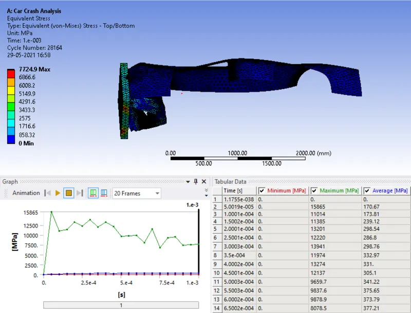
Case 3: Parametric Value of 1mm
Total deformation
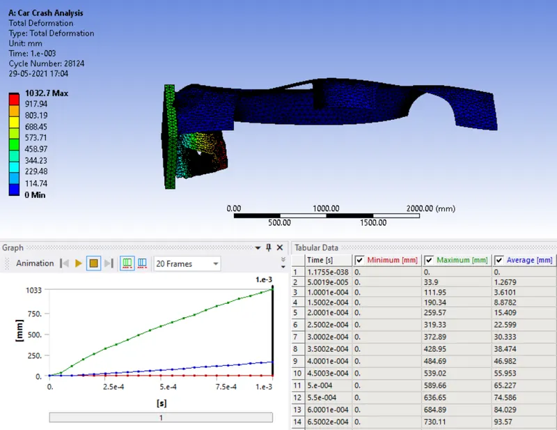
Equivalent Stress :
CONCLUSION :
Case 1 : 0.3mm
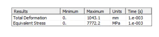
Case 2 : 0.6mm

Case 3: 1mm

- Maximum stress is directly proportional to the thickness of the car body surface.
- A Total Deformation is inversely proportional to the thickness of the car body surface.
- From the above comparison table, it’s clear that the more the wall thickness of the car body lesser is the deformation & the equivalent stresses. Hence, Case 3 (1 mm) has the least deformation & equivalent stress.