Week 11- Assembly Workbench
AIM
To Create the quick return mechanism from the given 2D drawings in CATIA V5
SOFTWARE USED
CATIA V5
PROCEDURE
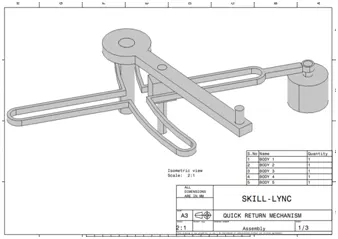
- Create a separate CATPART for all the body given in above drawing
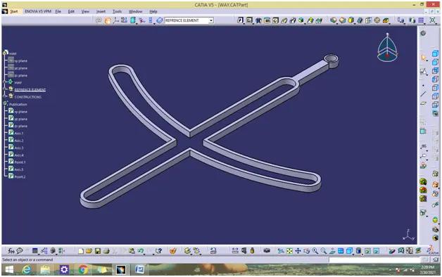
BODY 1 – WAYS
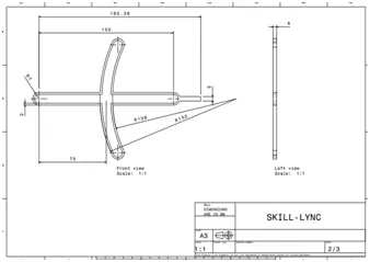
- Create a all sketch by using positioned sketch command
- Ensure that all the sketches in iso- constrained
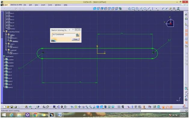
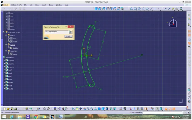
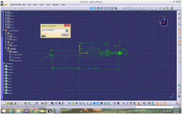
- Use pad command for thicken the solid for all the above sketch
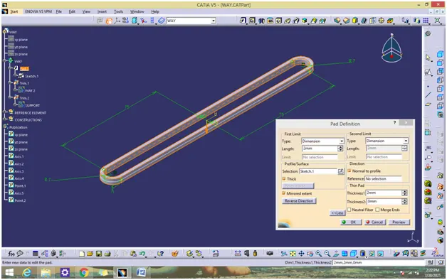
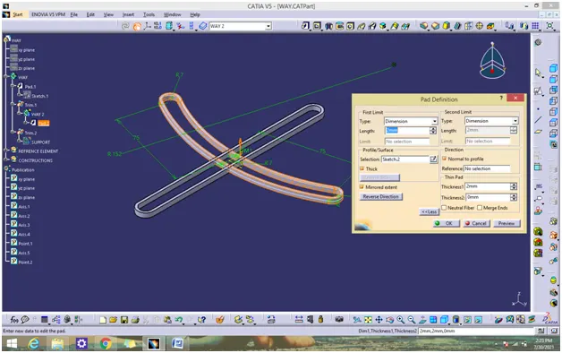
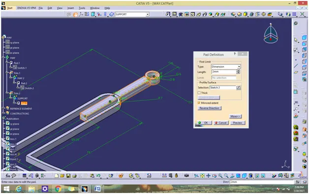
- Join all the solids to form body 1 solid by using Boolean operation (trim and add)
BODY 2 - ROTATOR
- Create a all sketch by using positioned sketch command
- Ensure that all the sketches in iso- constrained
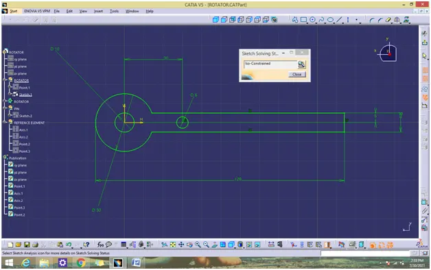
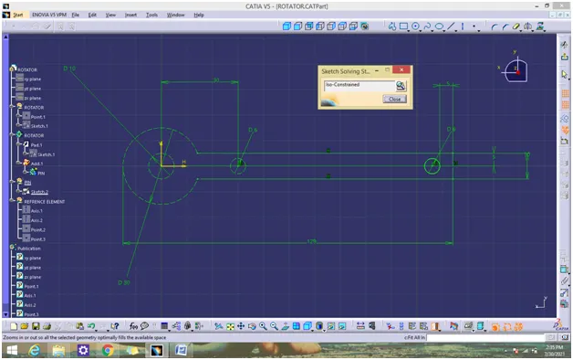
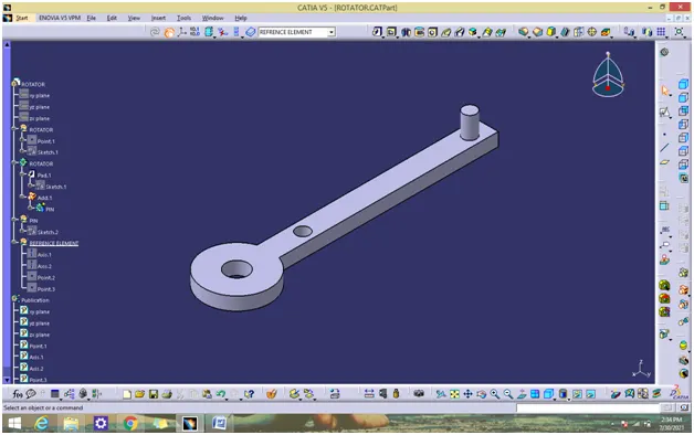
- Use pad command for thicken solid for all the above sketch
- Join all the solids to form body 2 solid by using Boolean operation (add)
BODY 3 – CYLINDER BLOCK
- Create a all sketch by using positioned sketch command
- Ensure that all the sketches in iso- constrained
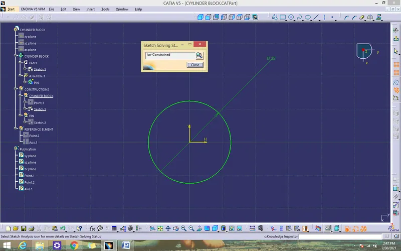
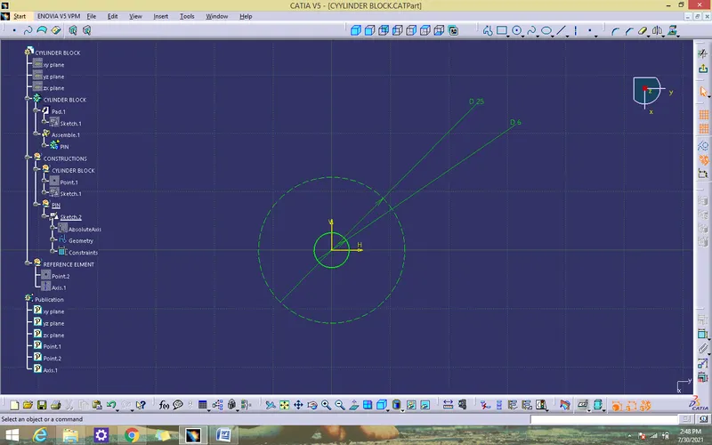
- Use pad command for thicken solid for all the above sketch
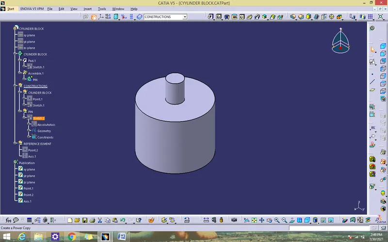
- Join all the solids to form body 2 solid by using Boolean operation( add and assemble)
BODY 4 – MECHANISM PIN
- Create a all sketch by using positioned sketch command
- Ensure that all the sketches in iso- constrained
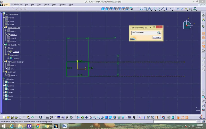
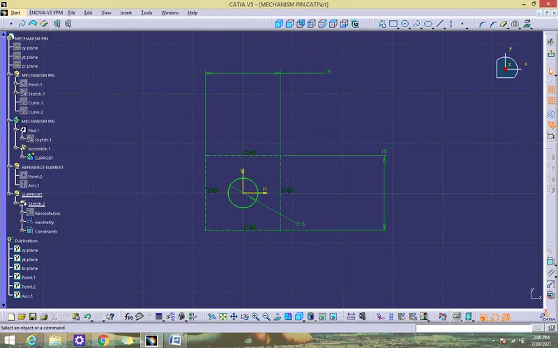
- Use pad command for thicken solid for all the above sketch
- Join all the solids to form body 2 solid by using Boolean operation ( add and assemble)
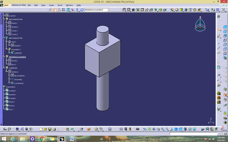
BODY 5 – ROTATOR PIN
- Create a all sketch by using positioned sketch command
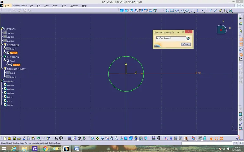
- Ensure that all the sketches in iso- constrained
- Use pad command for thicken solid for the above sketch
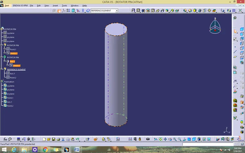
ASSEMBLE ALL CATPART
- Create a new CATproduct and insert all the above separate CATPART by using existing component command or copy/paste.
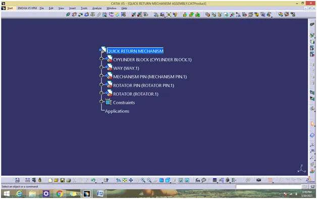
- Create a reference elements for all catparts.
- Add Reference elements like axis, points wherever we need
- Use publication tool to make all the necessary elements like planes,points,axis to make visible
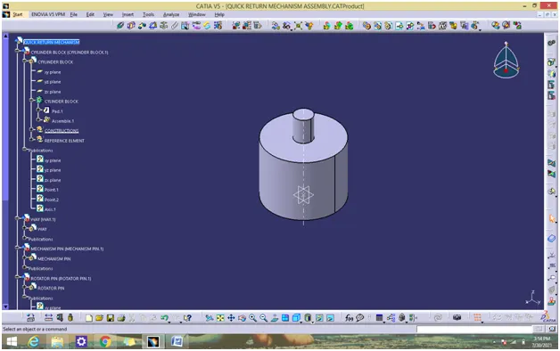
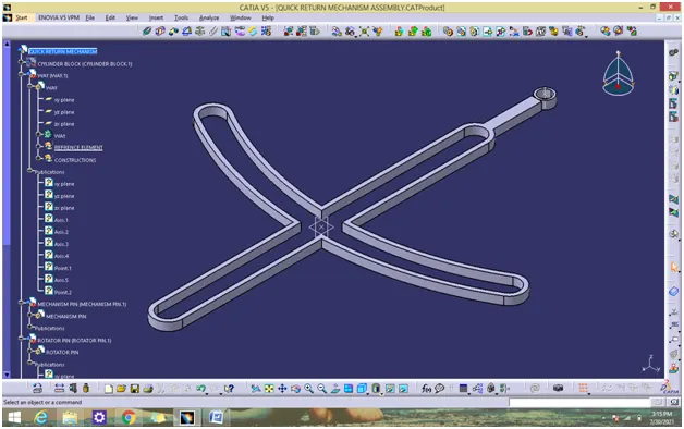
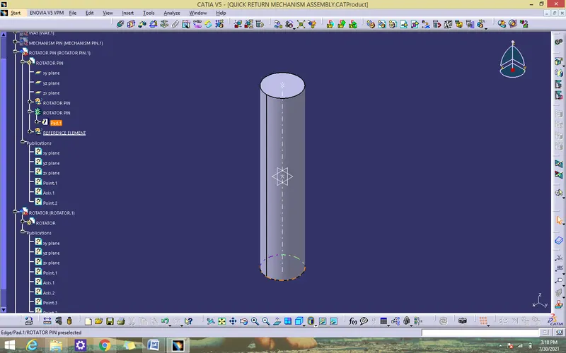
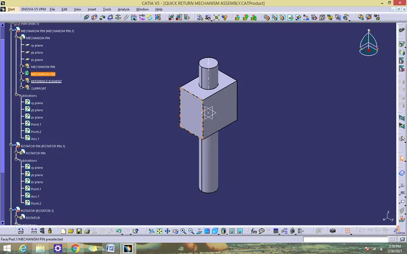
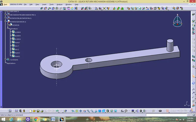
ASSEMBLY PROCEDURE
- Fix the cylinder block by using the fix component command
- Coincidence the cylinder block axis with way axis to block x, y move by using coincidence constraint
- Coincidence the cylinder block point with way point to block z move by move by using coincidence constraint
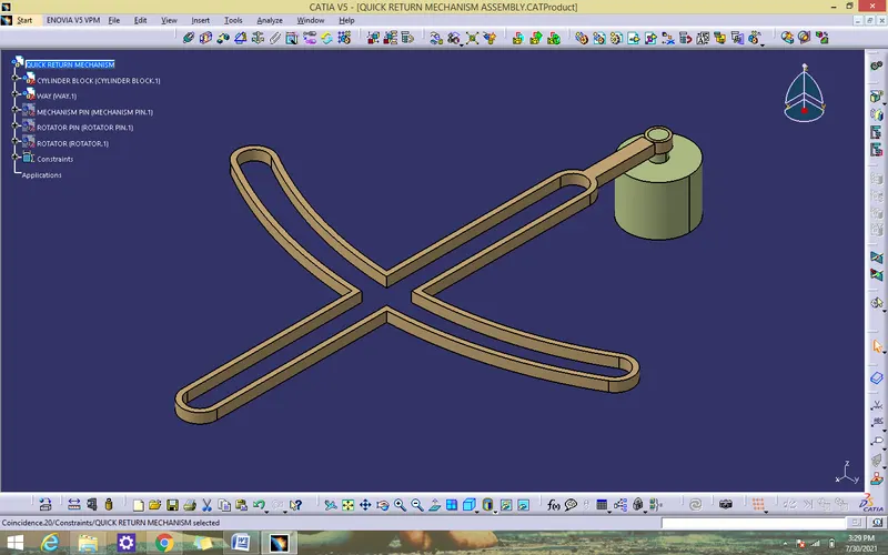
- Coincidence the cylinder block zx plane with mechanism pin zx plane to block x manipulation by using coincidence constraint
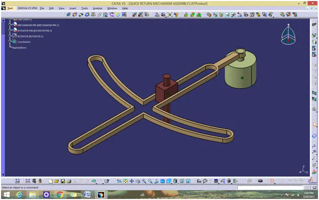
- Coincidence the way surface with rotator pin surface by using contact constraint
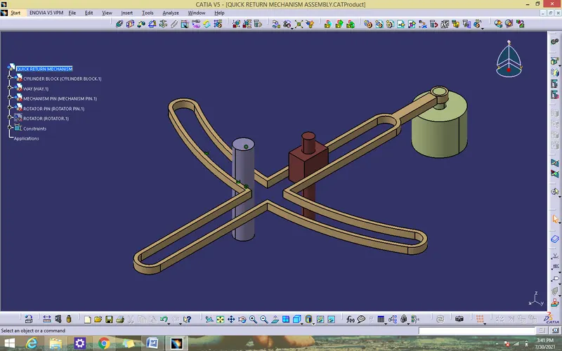
- Coincidence the rotator pin axis with rotator axis by using coincidence constraint
- Coincidence the rotator pin point with rotator point by using coincidence constraint
- Coincidence the mechanism pin point with rotator point by using coincidence constraint
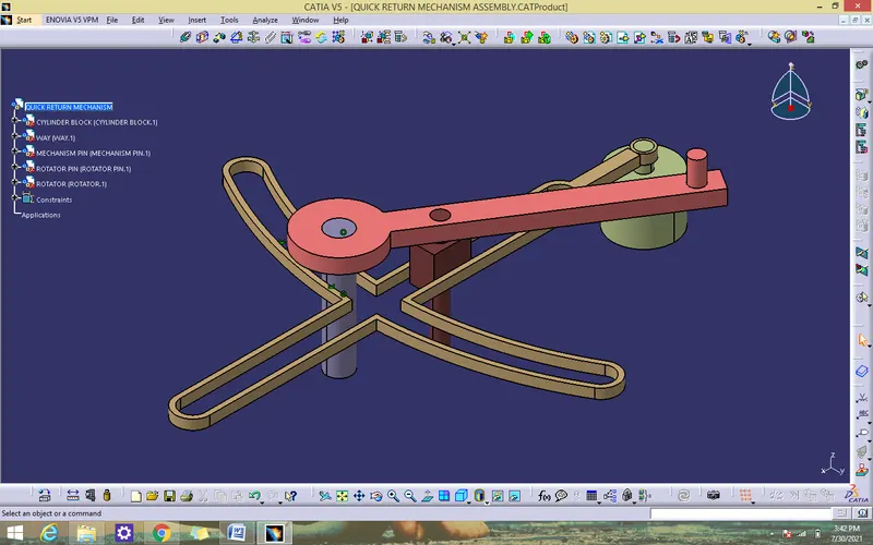
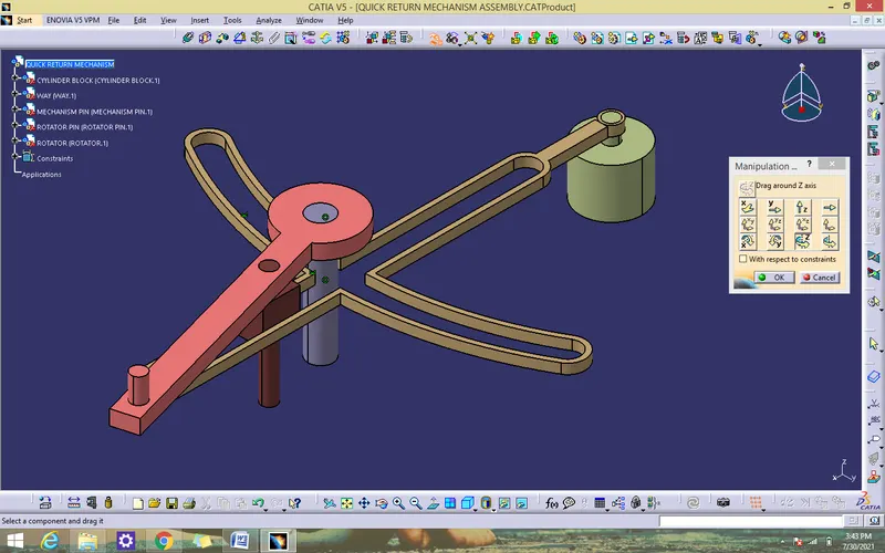
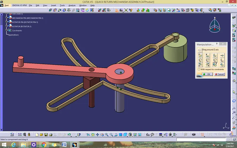
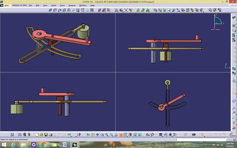
ISOMETRIC VIEWS
CONCLUSION
Quick return mechanism been created by using catia v5.
AIM
To Create the cv joint from the given 2D drawings in CATIA V5
SOFTWARE USED
CATIA V5
PROCEDURE
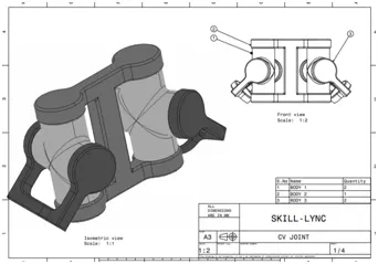
- Create a separate CATPART for all the body given in above drawing
BODY 1 – RING
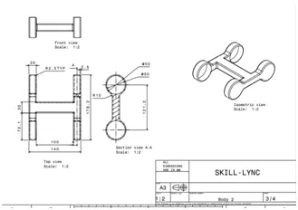
- Create a all sketch by using positioned sketch command
- Ensure that all the sketches in iso- constrained
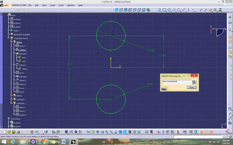
- Use extrude to extend the ring
- Create a line by using point direction and extrude the line to make ring close
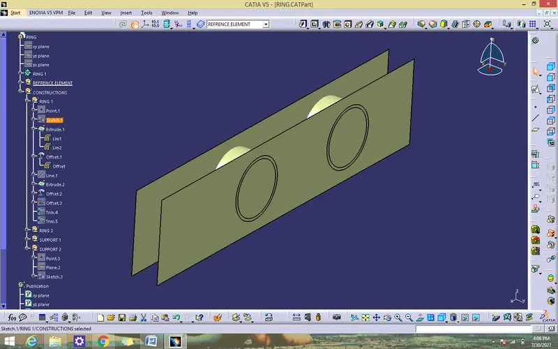
- Offset the above line surface and trim the ring surface with line surface
- Use close body surface to make a ring solid

- Create a support for ring by using positioned sketch
- Ensure that all the sketches in iso- constrained
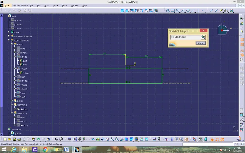
- Use pad command for thicken solid for the support
- Union trim the ring solid with support
- Use mirror command to form another ring
- Create a support for ring by using positioned sketch
- Use pad command for thicken solid for the support
- Union trim the ring solid with support
- Add fillets to all the edges
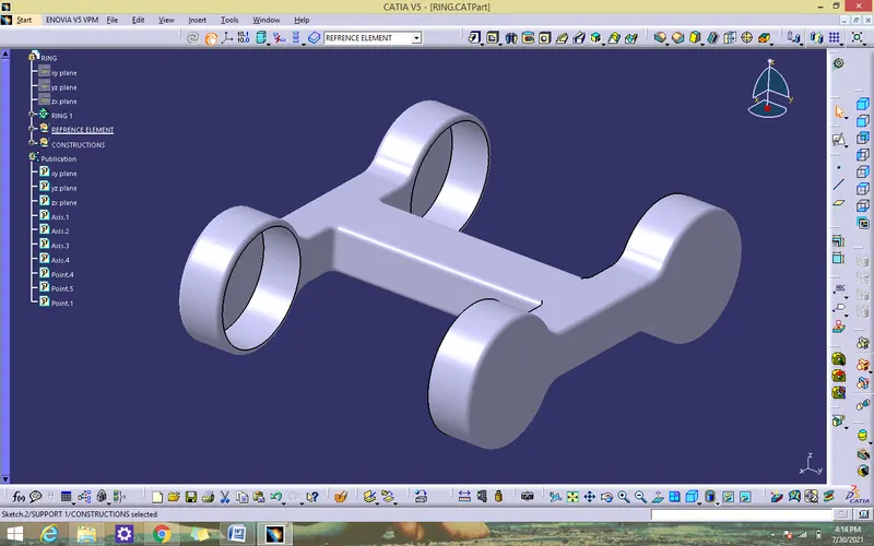
BODY 2-THREE FACE RING
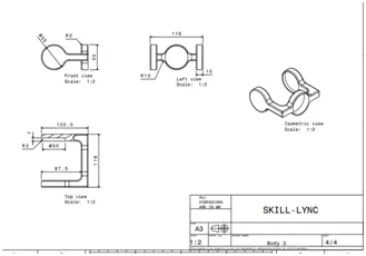
- Create a sketch by using positioned sketch command
- Ensure that all the sketches in iso- constrained
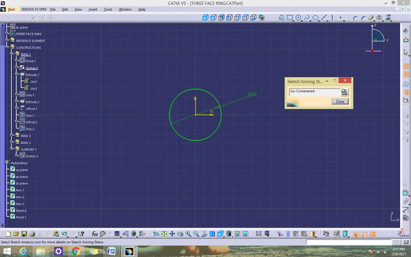
- Use extrude to extend the ring
- Create a line by using point direction and extrude the line to make ring close
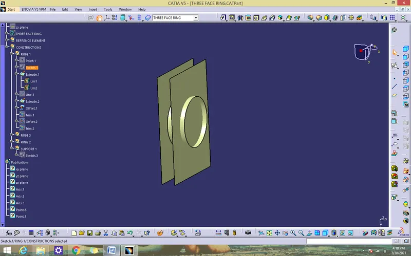
- Offset the above line surface and trim the ring surface with line surface
- Use close body surface to make a ring solid
- Use mirror command to form another ring
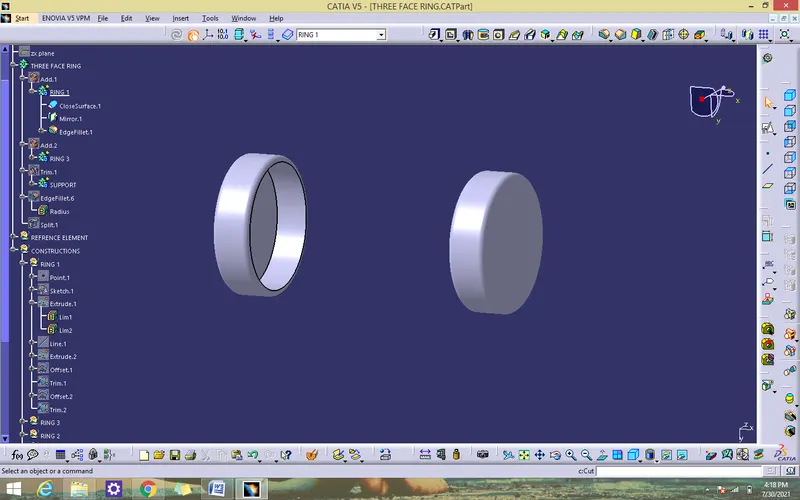
- offset the plane to form another ring
- Create a sketch by using positioned sketch command
- Ensure that all the sketches in iso- constrained
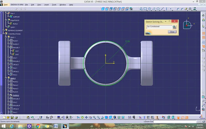
- Use extrude to extend the ring
- Create a line by using point direction and extrude the line to make ring close
- Offset the above line surface and trim the ring surface with line surface
- Use close body surface to make a ring solid
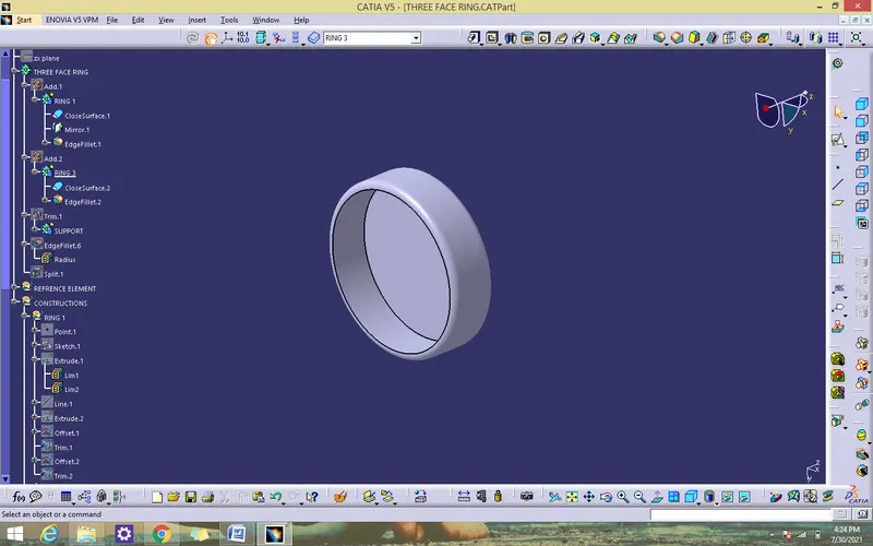
- Create a support sketch for rings by using positioned sketch
- ensure that sketch in iso-constrained
- Use pad command for thicken solid for the support
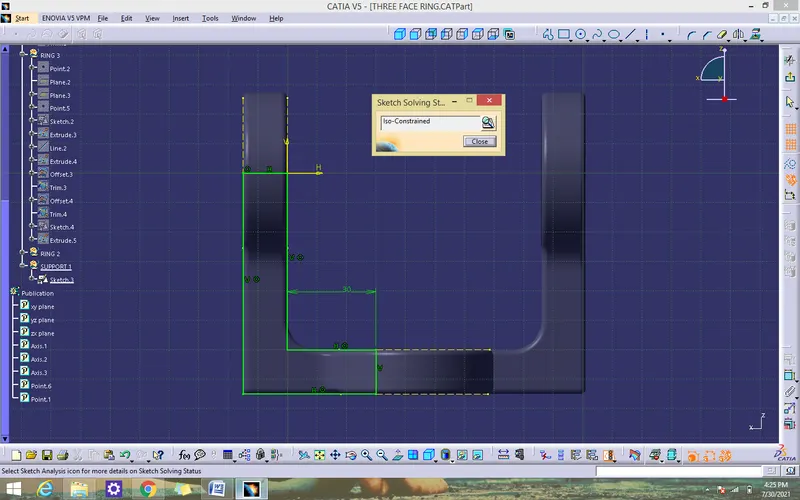
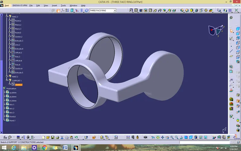
- Union trim the ring solid with support
- mirror the support
- Add fillets to all the edges
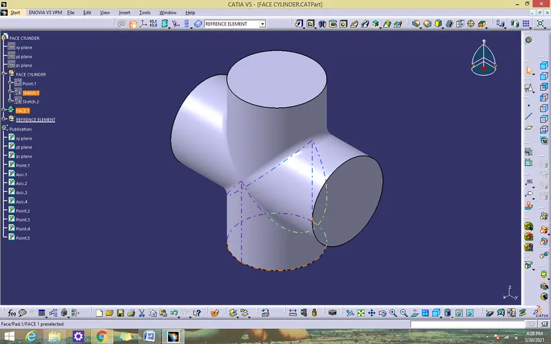
BODY 3 – FACE CYLINDER
- Create a sketch by using positioned sketch command
- Ensure that all the sketches in iso- constrained
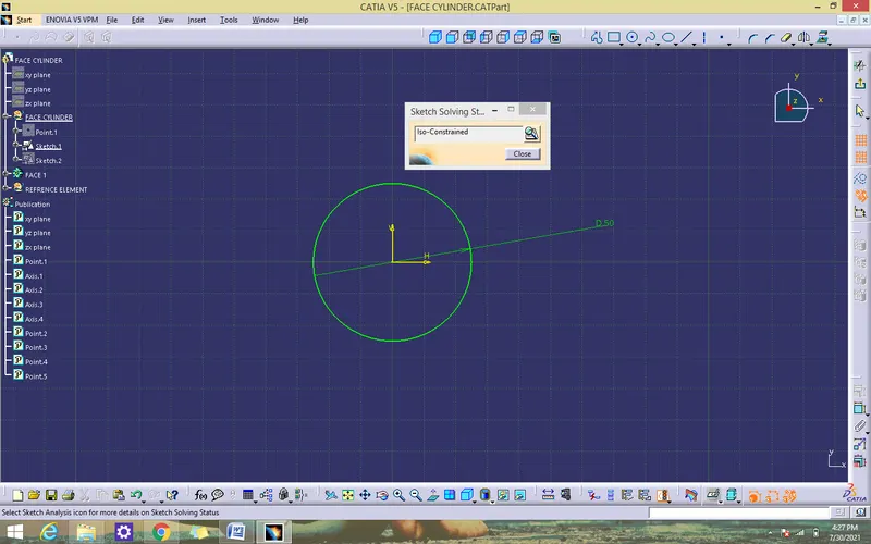
- Use pad command for thicken solid for all the above sketch
- create a same sketch in zx plane to form same solid
- Join all the solids to form solid by using Boolean operation (add)
- add fillets to edges
ASSEMBLE ALL CATPART
- Create a new CATproduct and insert all the above separate CATPART by using existing component command or copy/paste.
- Create a reference elements for all catparts.
- Add Reference elements like axis, points wherever we need
- Use publication tool to make all the necessary elements visible.
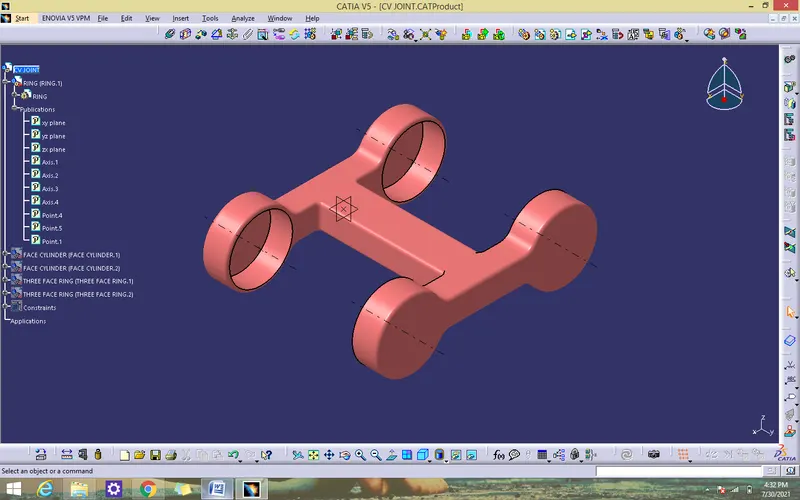
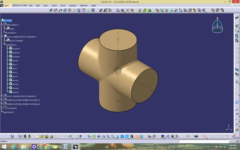
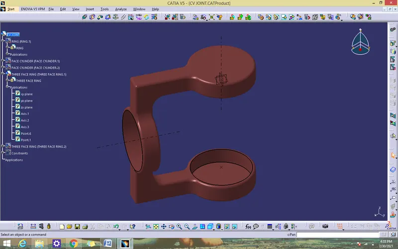
ASSEMBLY PROCEDURE
- copy the three face ring and face cyilder and paste to make another one
- Fix the ring by using the fix component command
- Coincidence the ring axis with cylinderblock to block x, y manipulation by using coincidence constraint
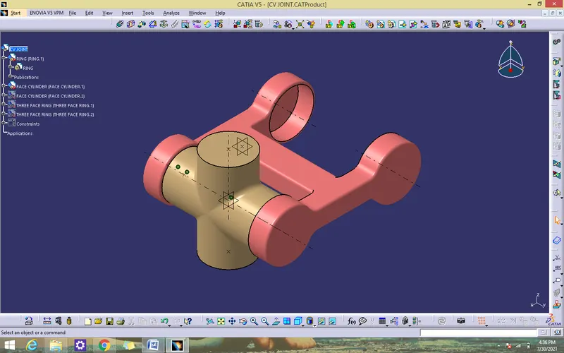
- Coincidence the ring axis with another cylinderblock to block x, y manipulation by using coincidence constraint
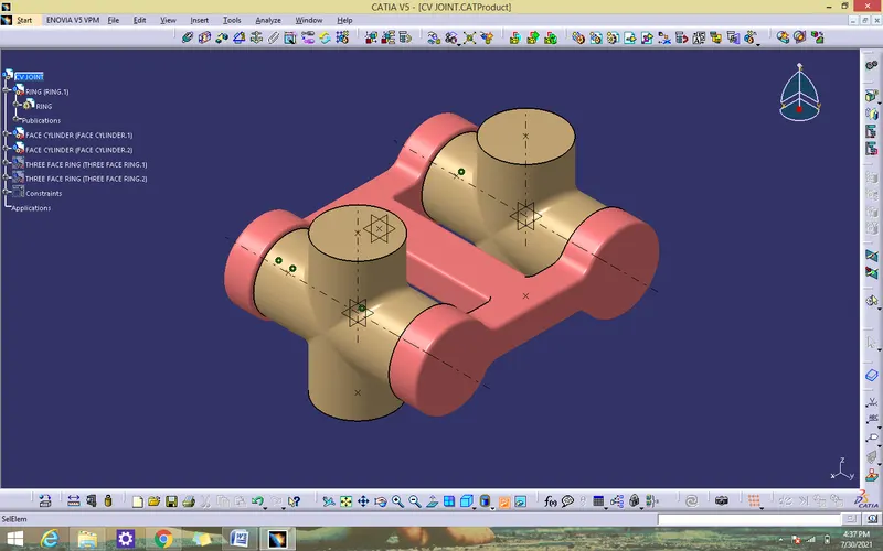
- Coincidence the three face ring point withcylinder block point by using coincidence constraint
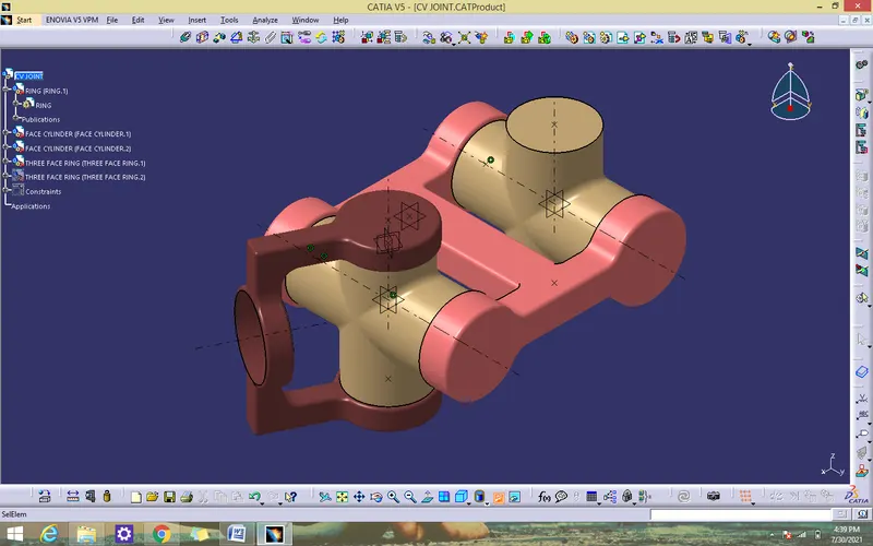
- Coincidence the another three face ring point with cylinder block point by using coincidence constraint
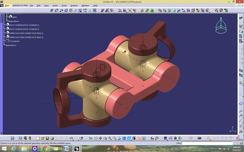
ISOMETRIC VIEW
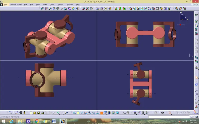
CONCLUSION
CV JOINT been created by using catia v5.