Week 11-3D Tetra Meshing Challenge
Week 8-3D Tetra Meshing Challenge
Creation of 3D Tetra mesh on the components by using hypermesh.
AIM:
To create 3D tetra mesh on the given models by using 2D to 3D conversion, quick tetra mesh and volume tetra mesh in hyper mesh with constrained 3D quality criteria.
PROCEDURE:
In finite element analysis choosing the right element for discretization during the pre-processor defines the quality of result that too how we are results on the convergence aspects. On this regard of selection of element also defines the computational time involved in the simulation.
The convenient and simplex way for simulation of sheet metal and plastics components is by generation of mid surface and followed by 2D meshing and finally assigning the thickness. This scenario is only applicable for the components which are having 6 and less than 6 mm thickness. The components which are having the thickness of more than 6 mm will be modeled by solid or 3D meshing. The elements which is preferable for the 3D meshing is tetra elements and if the pre-processing is for components which are subjected to durability can be modeled by quad element.
In hypermesh there are 3 methods to perform the 3D tetra meshing. They are i) 2D to 3D conversion, ii) quick tera meshing, iii) volume tetra meshing. The below mentioned procedure describes the 3 ways of 3D tetra meshing with separate models.
MODEL 1: 2D to 3D conversion tetra meshing.
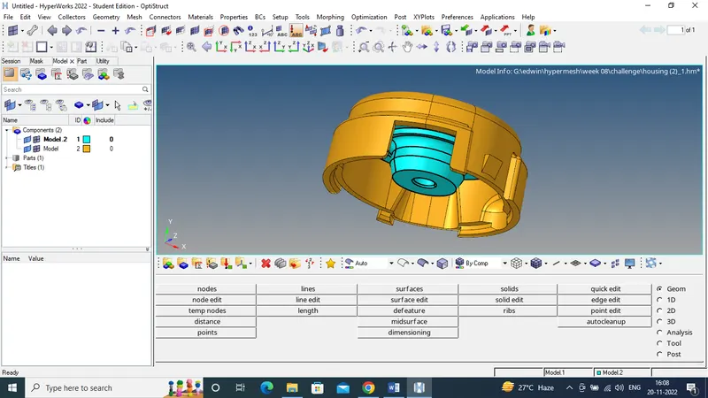
- The model has to be imported in our user interface and followed by which the orientation has to be checked.
-
Figure 1 M1. imported CAD
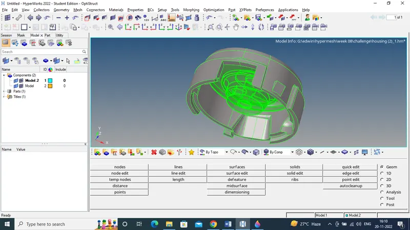
- For 3D tetra meshing by using 2D to conversion method the first step what has to be done is to check for any solids present in our model. If it exists, solids have to be deleted by using the option delete>>solids>>delete entity. The below mentioned image shows the exitances of solid in the model.
-
Figure 2 M1 identification of solids on the model
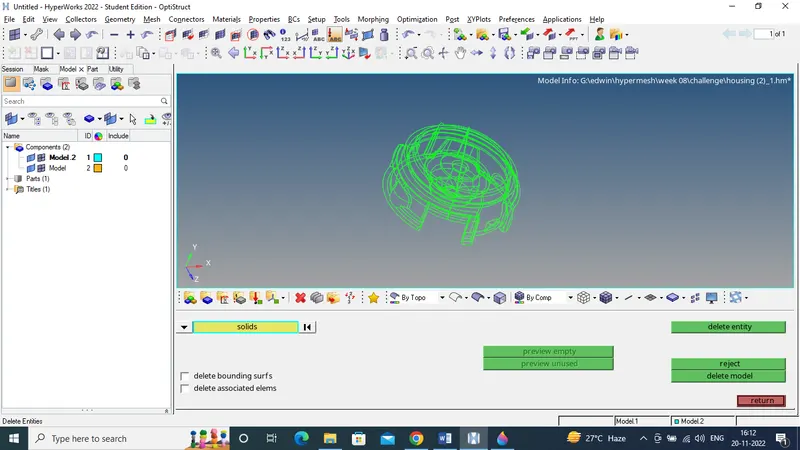
- After deleting the solids the model has to be checked for the free edges by switching the option wireframe geometry on and geometry clean-up has to be done by using the option geometry>>autocleanup>>surface.
-
Figure 3 M1. check for free edges in wireframe geometry.
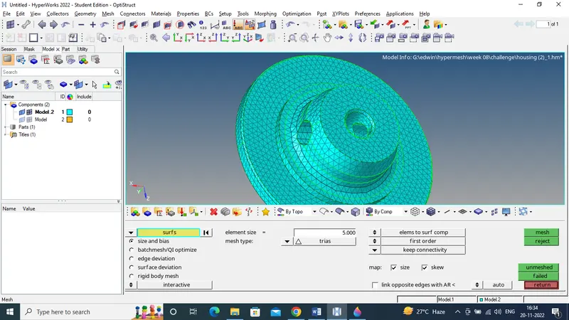
- The component is then meshed by using the option 2D>>automesh>>surface>>mesh. The entire is meshed with tria element and having quality criteria as minimum element size=2 mm, maximum element size=7, target element size=5 mm. the below image shows the 2D meshing and nil quality error in the model.
-
Figure 4 M1 performing 2D tria mesh on the surface
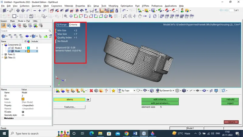
-
Figure 5 M1 cleared quality error in 2D tria mesh
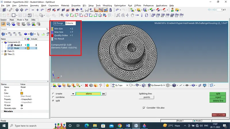
-
Figure 6 M1 cleared quality error in 2D tria mesh
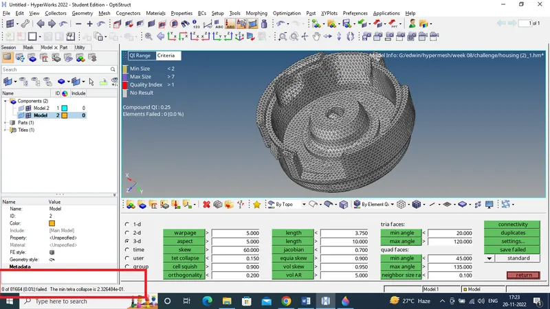
- The 2D mesh should be checked for any free edges this has to be done for smooth generation of tetra mesh in the enclosed 2D mesh. After 2D tria mesh has been generated we have to create the 3D tetra mesh by using the option 3D>>tetra mesh>>tetra mesh>>elements>>mesh. After 3D tetra mesh has been created it has to be checked for 3D quality criteria Tet collapse for 0.15.
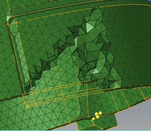
-
Figure 7 M1. generated 3D tetra mesh in the enclosed 2D mesh
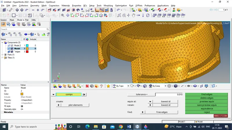
-
Figure 8 M1 finding the free edges during the 3D tetra meshing
-
Figure 9 M1 nil error for Tet collapse
MODEL 2: Quick tetra mesh.
- In 2D to 3D tetra mesh is 2 step process were 2D mesh and 3D mesh are carried separately while performing quick tetra mesh 2D and 3D mesh will be working simultaneously and the mesh will be generated on the boundary.
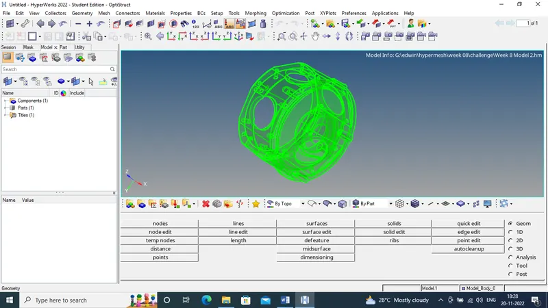
- Model 2 has been imported in the user interface.
-
Figure 10 M2 imported solid component
-
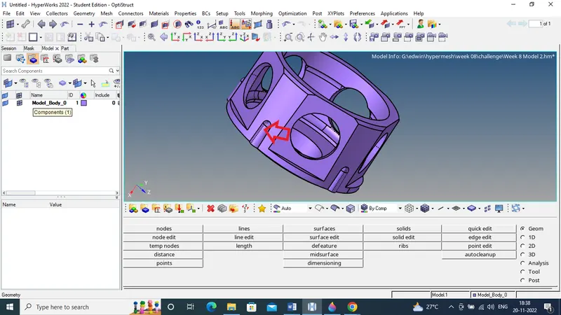
Figure 11 M2 auto clean-up done in the component
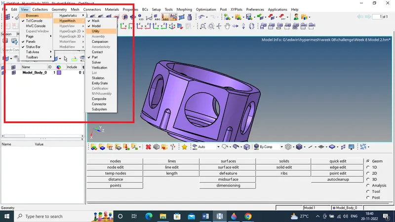
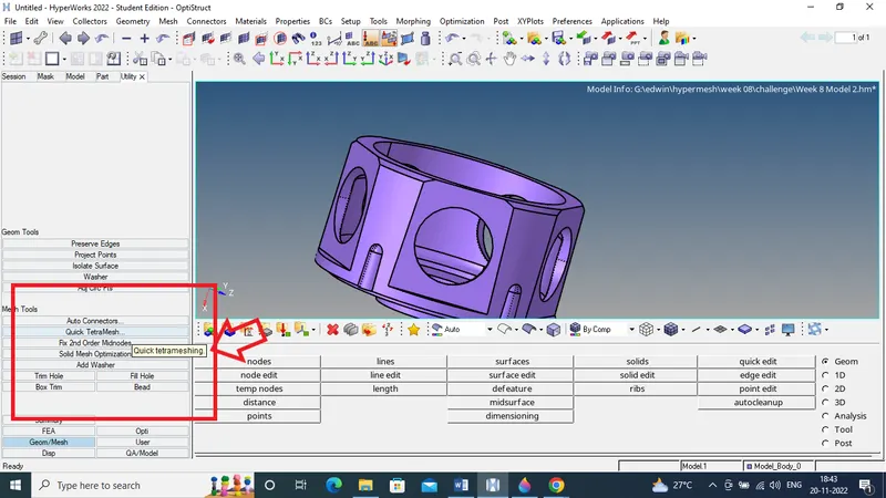
- Quick tetra mesh is performed by using the option view>>browesers>>hypermesh>>utility. The utility tab will be opened and you have to click the geom/mesh Followed by which you have to click quick tetra mesh.
-
Figure 12 M2 option for quick tetra mesh
-
Figure 13 M2 option for quick tetra mesh
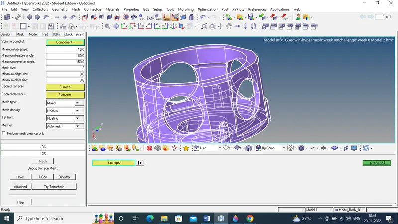
- A separate quick tetra mesh tab will be opened and component has been selected and clicking mesh button will generate the volume mesh.
-
Figure 14 M2 quick mesh panel
-
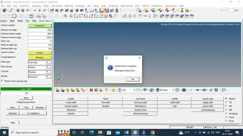
Figure 15 M2 task completed dialog box on quick tetra mesh
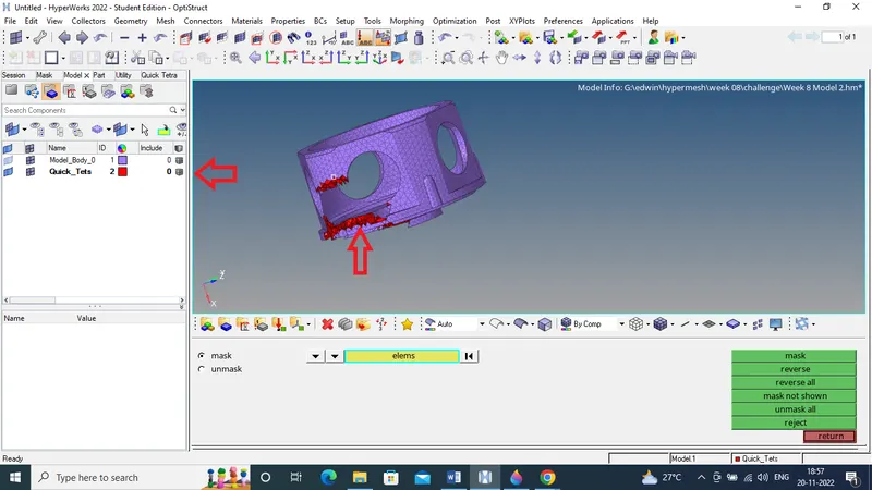
- When the tetra mesh has done dialog box will be displayed and shows the message. 2D and 3D mesh can be viewed separately by doing mask on the component will show the tetra mesh in the enclosed region.
-
Figure 16 M2 generated tetra mesh in the component
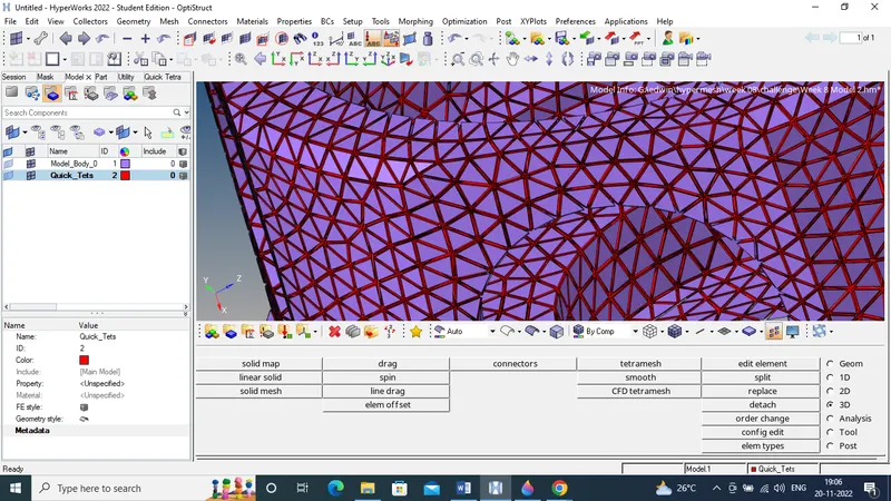
- We can also see the 2D and 3D separately by using shink element. This can be shown in below image.
-
Figure 17 M2 association 2D mesh on the surface and tetra mesh on the volume.
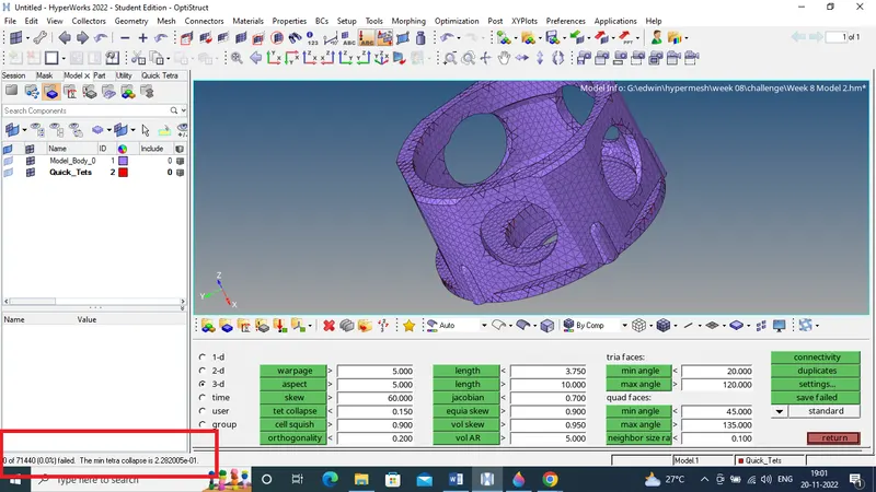
- All the errors in the tetra mesh has been cleared for tet collapse.
-
Figure 18 M2 nil error for Tet collapse
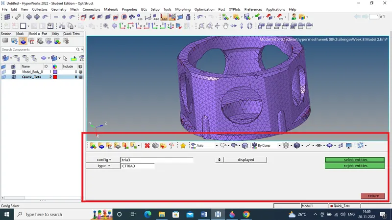
- We can also remove the meshed 2D elements by using the option delete>>elements>>by config>>tria3>>type=CTRIA3>>select entities>>delete entities.
-
Figure 19 M2 for deleting 2D mesh
MODEL 3: Volume tetra mesh.
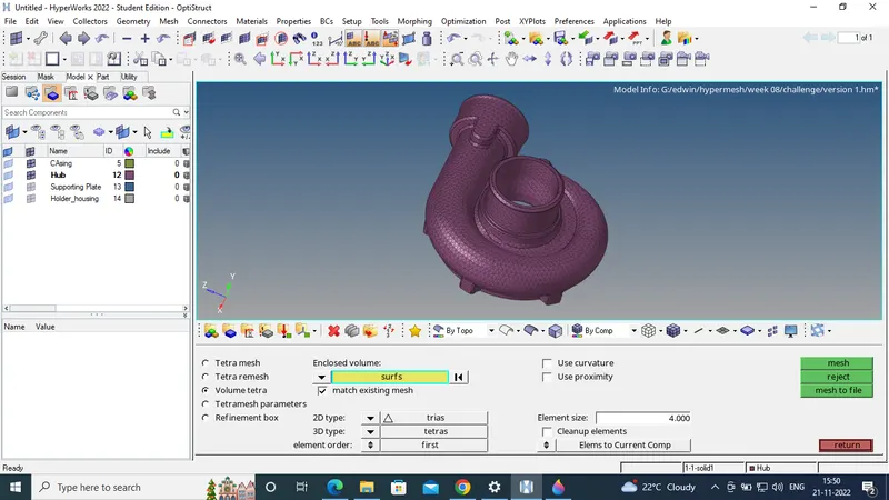
- Volume tetra mesh will be carried out in solids and surface and the model should be enclosed. Most probably all the steps followed will be similar to other methods will be same. Volume tetra mesh can be created by using the option 3D>>tetra mesh>>volume tetra>>surface>>2D type=trias>>3D type= tetras>>mesh
-
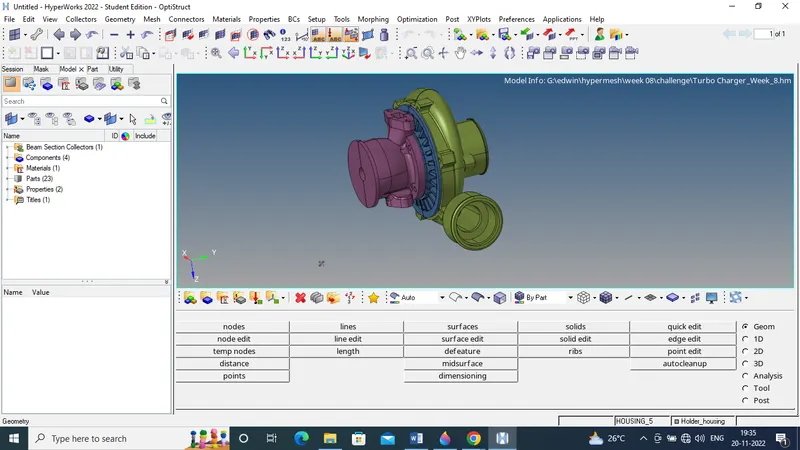
Figure 20 M3 imported model
-
Figure 21 M3 tetra meshing by volume generation
-
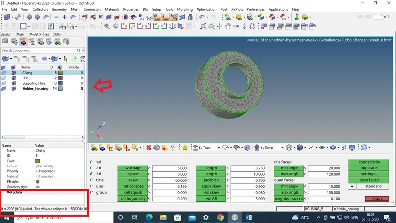
Figure 22 M3 tetra meshing with 0 Tet collapse
-
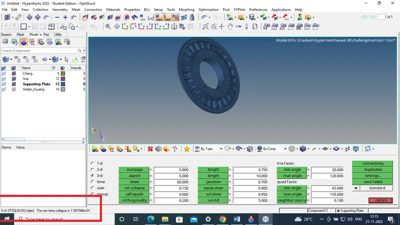
Figure 23 M3 tetra meshing with 0 Tet collapse for support plate
-
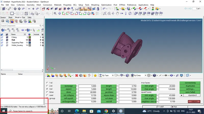
Figure 24 M3 tetra meshing with 0 Tet collapse for hub

-
Figure 25 M3 tetra meshing with 0 Tet collapse for casing
Result:
The given components have been meshed using 3D tetra elements by using 2D to 3D conversion method, quick tetra mesh method and volume tetra mesh method in hyper mesh with constrained 3D quality criteria. The final meshed components are shown below.
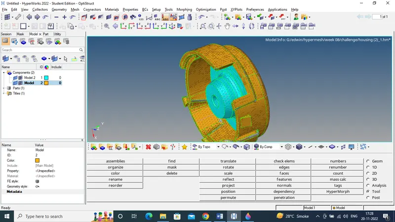
Figure 26 M1 final model after 3D meshing by using 2D to 3D conversion
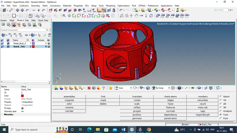
Figure 27 M2 final 3D tetra mesh on the component by using quick tetra mesh
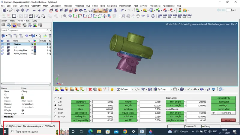
Figure 28 M3 final 3D meshed component with tetra mesh by using volume tetra mesh