Week 10 - Simulating Combustion of Natural Gas.
Aim – battery thermal management simulation using ANSYS fluent.
Introduction - All-electric vehicles, also referred to as battery electric vehicles (BEVs), have an electric motor instead of an internal combustion engine.
Electric vehicles use electricity to charge their batteries instead of using fossil fuels like petrol or diesel. Electric vehicles are more efficient, and that combined with the electricity cost means that charging an electric vehicle is cheaper than filling petrol or diesel for your travel requirements.
The increase in the number of electric vehicles on the road will reduce the demand for millions of barrels of oil in the future.
All-electric cars produce zero tailpipe emissions on the road, while being cheaper, smoother and quieter to run than their combustion-engine counterparts.
Improved battery technology: the key to superior EV performance & affordability. Battery technology has improved significantly in the past decade, with lithium-ion battery prices falling by approximately 85% from 2010 to 2018. This has also helped to increase EV range by about 17% per year over the last ten years.
Batteries are significant for their great ability to power a variety of devices, being able to be used in everything from cars to music players. The utility of batteries has made them indispensable to modern life. 1. Batteries are required to power the massive amounts of electronics used in the modern world.
Most of today's all-electric vehicles and PHEVs use lithium-ion batteries, though the exact chemistry often varies from that of consumer electronics batteries. Research and development are ongoing to reduce their relatively high cost, extend their useful life, and address safety concerns in regard to overheating.
When talk about the problems that are associated with the electric vehicle battery the one major problem is Thermal runaway (or TR, for short) is a phenomenon that can affect rechargeable energy storage systems, including lithium-ion (Li-ion) batteries and valve-regulated acid (VRLA) batteries. The dangerous condition occurs when the temperature rapidly rises inside one of the battery cells.
Thermal Runaway - Thermal runaway begins when the heat generated within a battery exceeds the amount of heat that is dissipated to its surroundings.
Thermal runaway is the condition in which a battery catches fire due to rapid heat propagation from one damage cell to another cell.
At 80*c – solid electrolyte interface (SEI) layer of the negatively charged anode starts to decompose
100*c-120*c – electrolyte breakdown into exothermic reaction.
120*c-130*c – separator melted down and more heat is generated causing an internal short circuit.
130*c –150*c – positively charged cathode begins to decompose and produce oxygen.
150*c-180*c – cell becomes thermally unstable and a condition of thermal runaway (TR) is reached.
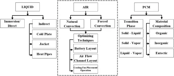
Battery Thermal Management System (BTMS) – To protect the battery from thermal runaway we need the battery thermal management system.
the device responsible for managing/dissipating the heat generated during the electrochemical processes occurring in cells, allowing the battery to operate safely and efficiently.
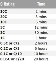
C- Rating – the C- rate is a unit to declare a current value which is used for estimating and or designating the expected effective time of battery under variable charge discharge condition.
The C-rate is the unit battery experts use to measure the speed at which a battery is fully charged or discharged. For example, charging at a C-rate of 1C means that the battery is charged from 0-100% in one hour.
Procedure – Here we are going to create the battery pack in the space claim then we will run some simulation for different case where we are going to create the enclosure and evaluating the natural heat convection of the heat which is being dissipate from battery pack to the environment.
The process is described in the following steps.
Step_1 setting up the geometry in the space claim.
- Start with the sketching in the XY-plane.
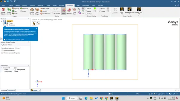
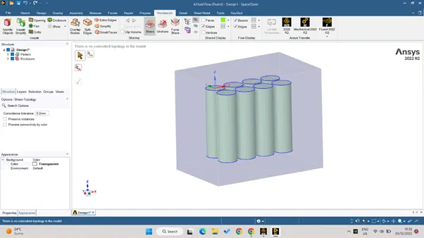
- Draw a circle at the origin of 18mm diameter, now pull the circle tom create the 3-D geometry till 65mm, here we are designing the 18650 Li-ion battery thus the dimensions are taken from there.
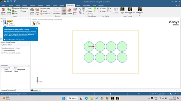
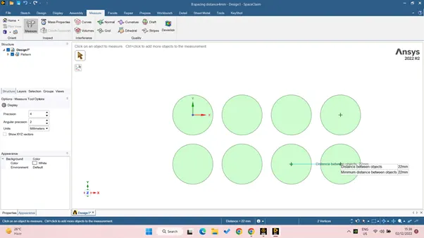
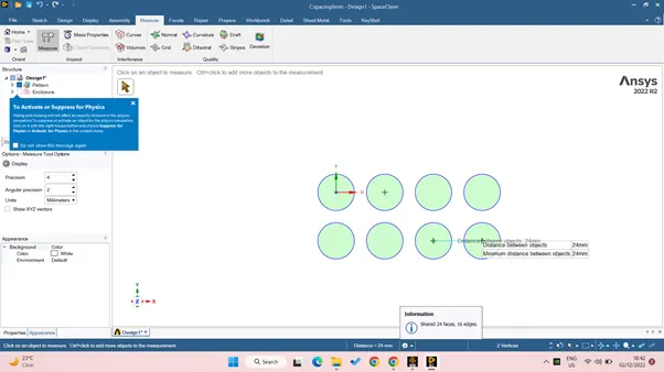
- By the use of pattern command under design create the 4*2 battery pack with the 2mm, 4mm and 6mm in between gap for three different case respectively.
- Create the enclosure around the pack with 18mm-22mm side spacing for further case and the 15mm top distance.
- Enable the share topology, unmark the preserve option, the battery edge will be changed with different colour which shows the share topology is working from enclosure to the edge of cell.
Step_2 meshing and pre-processing: -
- Generate the mesh.
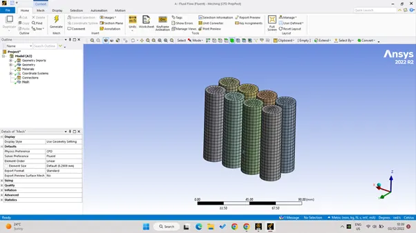
- The auto generate mesh will provide the appropriate mesh length for the model, also it has provided the multizone quad structured mesh to the battery pack.
- Under inflation select the program control inflation < update this will provide the random size inflation to the cell pack.
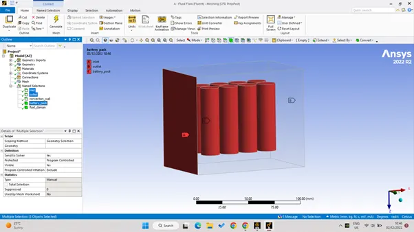
- One perpendicular side is named as the input for the air, and the symmetrical opposite size is named as the output
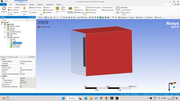
- The symmetry 4 side wall is named as the convection wall as the natural convection is assumed from this enclosure to the environment.
- All the cell together here named as the battery pack here, we can also provide the separate name for each and every battery.
- The domain around pack is named as the fluid domain.
- Here the approx. cell count is as 1.5lac.
- Here for the mesh independent study the other mesh is having the mesh length of 3mm. and the no of mesh elements are around 2.73 lac.
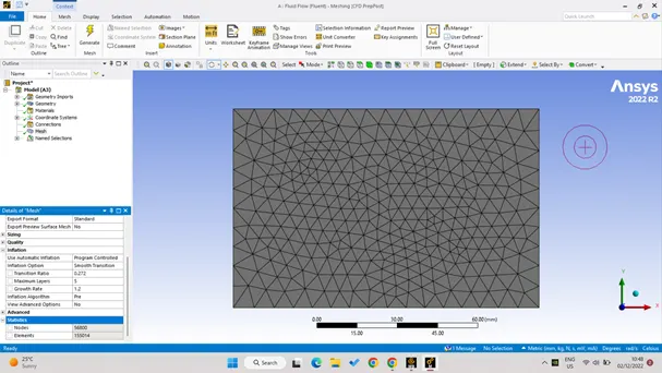
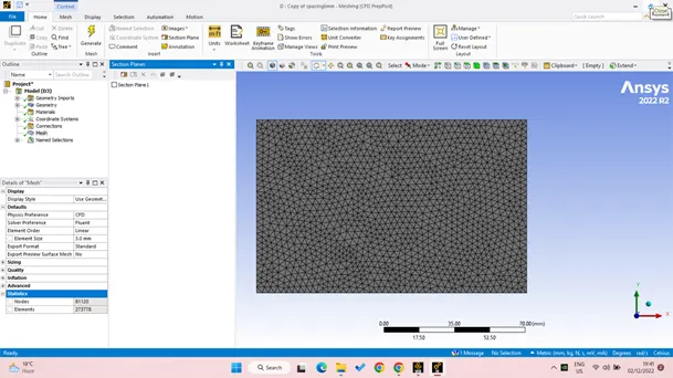
- The below mesh is for the 2mm in spacing between the cell, with the large mesh element size.
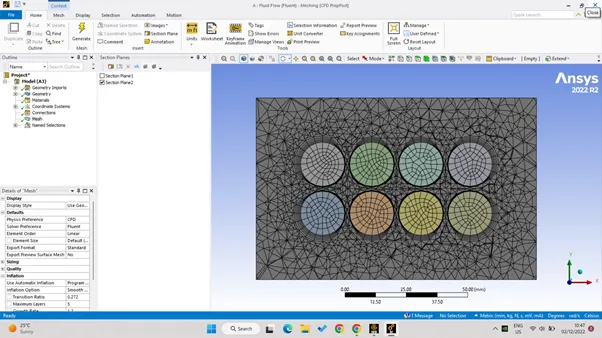
- This image below having the 3mm mesh element size thus the dense mesh elements, and for 4mm and 6mm in space distance respectively.
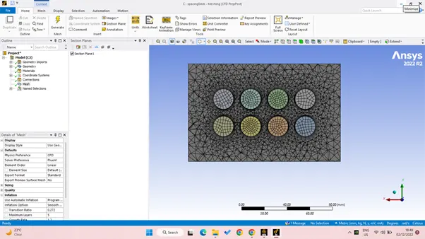
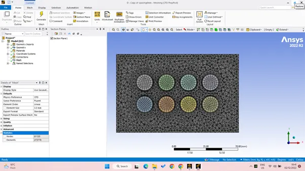
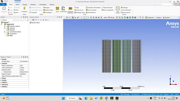
- The following below image is showing the mesh inside the enclosure as by section cut.
- the name selection for the domain is shown in the below images.
Step_3 – post processing and the solver setting.
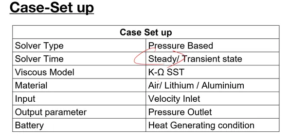
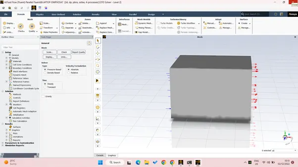
- The general solver setting is provided as the pressure based< absolute< steady state solver<enable energy.
- Viscous model as the k-omega SST as we are interested in the boundary HTC phenomena.
- Material selection –
|
Material name |
Used for |
Density(kg/m^3) |
Specific heat(J/kg.k) |
Conductivity(w/m.k) |
|
Lithium |
Batter pack |
2772 |
1200 |
37.6 |
|
polystyrene |
Enclosure |
100 |
600 |
0.1 |
- Cell zone material change into solid< lithium< source term< one< constant<48750w/m^3.
- The boundary condition is given as follows: -
- Convection wall < polystyrene< thermal convection< HTC value to 5 and the temperature as the 26 degree Celsius (room temperature).
- inlet as the velocity type and the inlet velocity as the parameter created for the different case for 3m/s, 5m/s and 10m/s for the different spacing and mesh independent study.
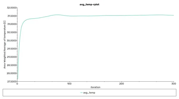
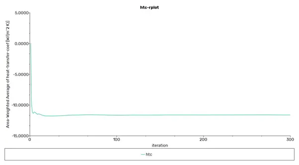
- Under definition provide some input plot for area weightage HTC and the avg. temperature, also for the maximum temperature.
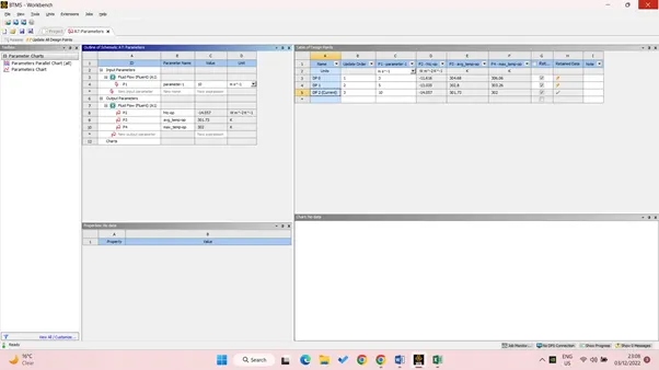
- Also create parameter and print to console for these plot as to see the result for various case.
Result – the result along with the following plot and contour which is generated by the fluent for the different case is shown here in the table and image form.
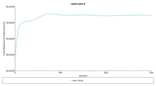
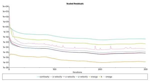
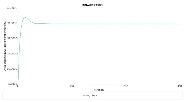
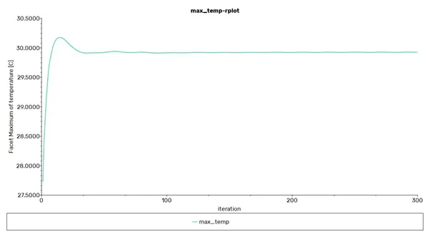
Also the plot shows how the convergence limits achieved for the particular case.
|
Case no . |
Cell gap |
Mesh element size |
Inlet velocity |
Age temp (Kelvin) |
Max temp (kelvin) |
Heat transfer coefficient (W/(m2°C)) |
|
Case_1 |
2mm |
9.5mm |
3m/s |
304.68 |
306.05 |
-11.61 |
|
Case_2 |
2mm |
9.5mm |
5m/s |
302.80 |
303.26 |
-13.03 |
|
Case_3 |
2mm |
9.5mm |
10m/s |
301.72 |
301.72 |
-14.056 |
|
Case_4 |
4mm |
9.5mm |
5m/s |
302.622 |
303.075 |
-13.20 |
|
Case_5 |
6mm |
9.5mm |
5m/s |
302.57 |
302.92 |
-13.24 |
|
Case_6 |
6mm |
3mm |
5m/s |
302.56 |
302.94 |
-13.26 |
Result conclusion from the table.
- The gap between cell does not much affect the avg temp also the heat transfer coefficient, only little increase can be seen here with the gap.
- But as the inlet velocity of air increase it affect the maximum temperature going much down also the highest heat transfer between cell and air, which justify the heat transfer coefficient is directly proportional to the air velocity.
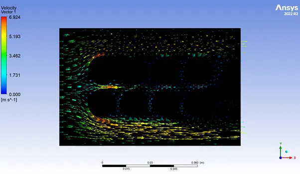
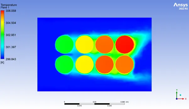
Below images shows the values for case-1 here we can also see the convergence has been reached.
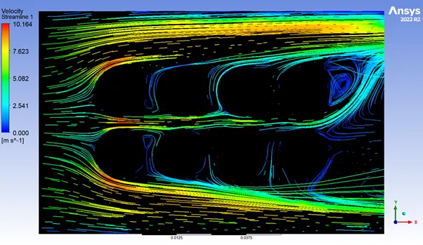
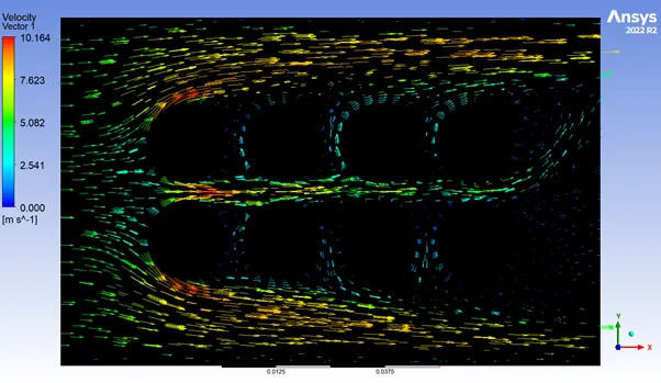
- The below images for the 4mm cell gap.
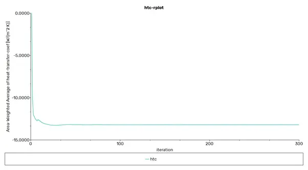
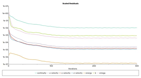
- The below plot is for the 6 mm cell gap.
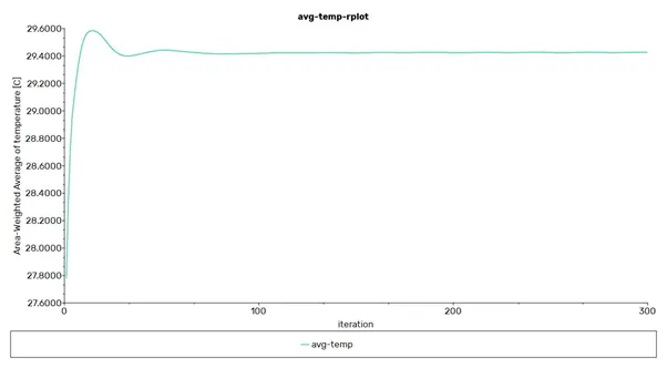
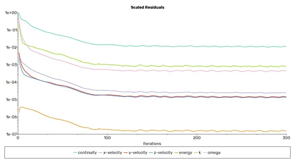
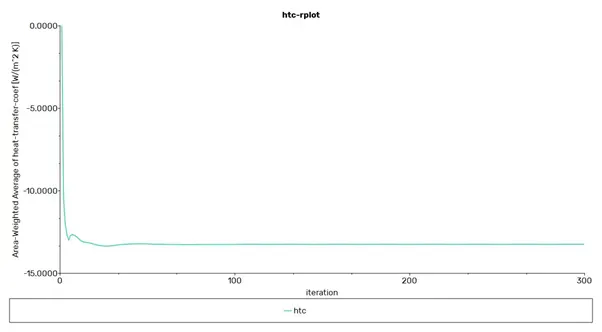
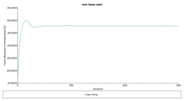
- The below images plot is for the 3mm mesh element size.
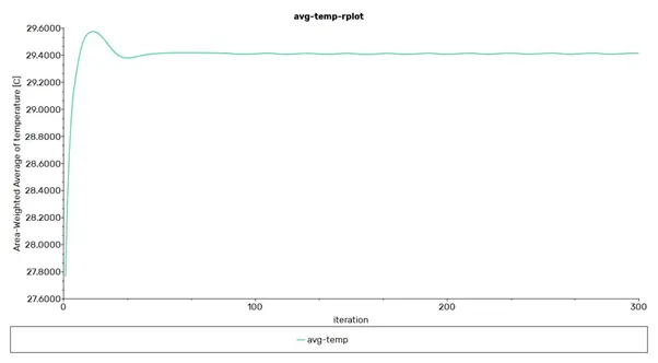
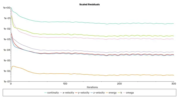
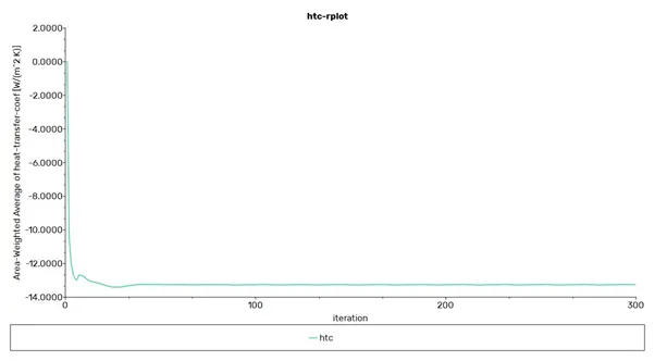
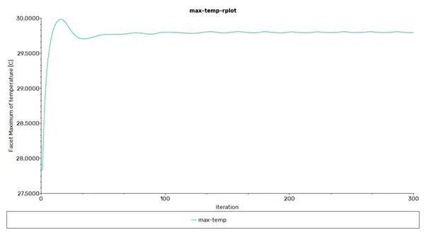
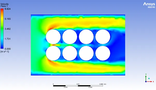
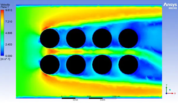
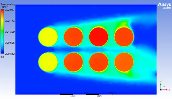
- Now the below images are for the different contour.
Case-1
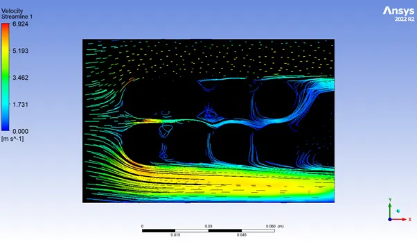
Case-4 with 4 mm cell gap.
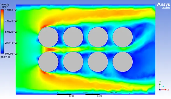
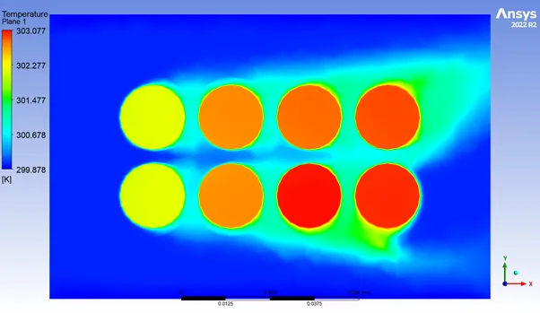
Case-5 with 6mm cell gap.
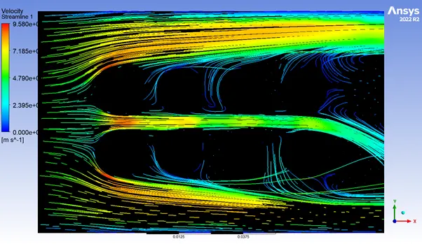
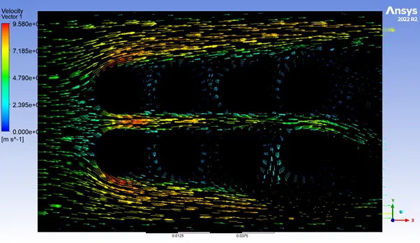
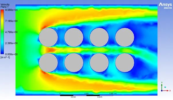
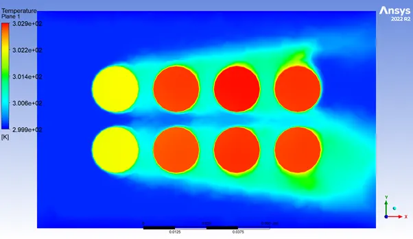
Case-6 with gap of 6mm and 3 mm mesh length.
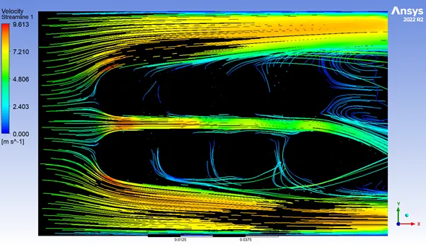
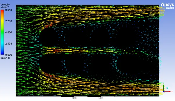
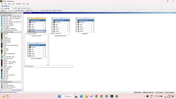
The parametric study for the different case.
Learning outcome – Here by observing the given contour we can see how the inlet air travelling around the cell and helping it to transfer the generated heat to the air by mode of convection heat transfer, and saving the batter pack from thermal runaway.
We can see the front cell row from where the air is coming has the lowest temperature thus it justifies the heat transfer convection is directionally proportional to the incoming velocity.
The value that we have provided for the heat generation source calculated by assuming the 1.5C rating that means the we are taking the high value output from battery and it will be discharged within 45mis thus it will generate the high amount of heat and also its temperature will increase soon, which will cause to reach the thermal runaway early. By dividing the volume of the cell we’ll have the heat generated per volume.
Also for the simulation purpose we have taken the constant value of the heat generation for the ease of calculation, but in the real case we know the heat generation is the function of time which keeps on increasing with the time, thus for such case we’ll have to provide the UDF function which had the relation between heat generated with the function of time.
Conclusion – Electric vehicle demand is increasing rapidly and batter is the power source of this vehicle, Li-ion battery that been used in the vehicle as the power source have the lots of advantages and on the other hand it also has a lot of disadvantages including the massive fire which can lead to burn the vehicle or even can cause death of the passengers.
Thus maintaining and taking care of the electric battery from catching fire it is important to check and regulate its preventive maintenance thus BMS and BTMS is used for this purpose.
Here in this simulation I have tried to generate the result which is helping in the understanding of one of the mode of BTMS the natural convection by the help of air and tried to run this simulation for different possible case, which somehow concluded the data that should be used for the particular batter pack.
Thus in this last challenge of the fluent I learned a lot of things, also did the parametric study for the different case which helped me ultimately saving a lot of time.