Week 10 - Simulating Combustion of Natural Gas.
AIM
- To perform the simulation and analysis using the methane -air mixture in combustion chambers form section and plot the variations of mass fractions of different species at different locations in combustions sections , and give results of pressure , temperature , velocity , mass fraction of ch4, co, co2 , o2 , h2o, N2, O2, NOx and soot pollutants. To plot the each results with sections and couture curve .
- To perform the simulation and analysis the results of methane air mixture with water in inlet air section , in proper proportional of mass fractions 10% ,20% and 30% of water with mixture.to give results of same pressure , temperature, mass fraction of ch4, co, co2 , o2 , h2o, N2, O2, NOx and soot pollutants , to figure out the result that what is the effect of water in combustion , to calculate the results how it reduce the temperature , nox and soot particles .
Introduction
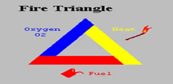
Combustion is the scientific word for burning. In a combustion reaction, a substance reacts with oxygen from the air. Combustion reactions happen at high temperatures, and transfer energy to the surroundings as light and heat. The original substance is called the fuel, and the source of oxygen is called the oxidizer.During combustion, new chemical substances are created from the fuel and the oxidizer. Three things are required in proper combination before ignition and combustion can take place---Heat, Oxygen and Fuel. There must be Fuel to burn. There must be Air to supply oxygen. There must be Heat (ignition temperature) to start and continue the combustion process.
Combustion is often a complicated sequence of elementary radical reactions. Solid fuels, such as wood and coal, first undergo endothermic pyrolysis to produce gaseous fuels whose combustion then supplies the heat required to produce more of them. Combustion is often hot enough that incandescent light in the form of either glowing or a flame is produced. A simple example can be seen in the combustion of hydrogen and oxygen into water vapor, a reaction commonly used to fuel rocket engines. This reaction releases 242 kJ/mol of heat and reduces the enthalpy accordingly (at constant temperature and pressure):
Combustion of an organic fuel in air is always exothermic because the double bond in O2 is much weaker than other double bonds or pairs of single bonds, and therefore the formation of the stronger bonds in the combustion products CO2 and H2O results in the release of energy.[2] The bond energies in the fuel play only a minor role, since they are similar to those in the combustion products; e.g., the sum of the bond energies of CH4 is nearly the same as that of CO2. The heat of combustion is approximately −418 kJ per mole of O2 used up in the combustion reaction, and can be estimated from the elemental composition of the fuel.
Stoichiometric combustion of a hydrocarbon in oxygen.
Generally, the chemical equation for stoichiometric combustion of a hydrocarbon in oxygen is

where 
For example, the stoichiometric burning of propane in oxygen is:

Stoichiometric combustion of a hydrocarbon in air.
If the stoichiometric combustion takes place using air as the oxygen source, the nitrogen present in the air (atmospheric air ) can be added to the equation (although it does not react) to show the stoichiometric composition of the fuel in air and the composition of the resultant flue gas. Note that treating all non-oxygen components in air as nitrogen gives a 'nitrogen' to oxygen ratio of 3.77, i.e. (100% - O2%) / O2% where O2% is 20.95% vol:

where  .
.
For example, the stoichiometric combustion of propane ( C3H8) in air is:

The stoichiometric composition of propane in air is 1 / (1 + 5 + 18.87) = 4.02% vol.
CHEMICAL KINETICS
Chemical kinetics, also known as reaction kinetics, is the branch of physical chemistry that is concerned with understanding the rates of chemical reactions. It is to be contrasted with thermodynamics, which deals with the direction in which a process occurs but in itself tells nothing about its rate. Chemical kinetics includes investigations of how experimental conditions influence the speed of a chemical reactions and yield information about the reaction mechanism and transition stste , as well as the construction of methamatical model that also can describe the characteristics of a chemical reaction.
CHEMICAL REACTION MODELS
Chemical reaction models transform physical knowledge into a mathematical formulation that can be utilized in computational simulation of practical problems in chemical engineering. Computer simulation provides the flexibility to study chemical processes under a wide range of conditions. Modeling of chemical reaction involves solving conservation equations describing convection, diffusion, and reaction source for each component species.
Species transport equation

Ri is the net rate of production of species i by chemical reaction and Si is the rate of creation by addition from the dispersed phase and the user defined source. Ji is the diffusion flux of species i, which arises due to concentration gradients and differs in both laminar and turbulent flows. In turbulent flows, computationl fluid dynamics also considers the effects of turbulant diffusivity. The net source of chemical species i due to reaction, Ri which appeared as the source term in the species transport equation is computed as the sum of the reaction sources over the NR reactions among the species.
REACTION RATE MODELS
hese reaction rates R can be calculated by following models:
- Laminar finite rate model
- Eddy dissipation model
- Eddy dissipation concept
Laminar finite rate model
The laminar finite rate model computes the chemical source terms using the Arrheunis expressions and ignores turbulence fluctuations. This model provides with the exact solution for laminar flames but gives inaccurate solution for turbulent flames, in which turbulence highly affects the chemistry reaction rates, due to highly non-linear Arrhenius chemical kinetics. However this model may be accurate for combustion with small turbulence fluctuations, for example supersonic flames.
Eddy dissipation model
The eddy dissipation model, based on the work of Magnussen and Hjertager, is a turbulent-chemistry reaction model. Most fuels are fast burning and the overall rate of reaction is controlled by turbulence mixing. In the non-premixed flames, turbulence slowly mixes the fuel and oxidizer into the reaction zones where they burn quickly. In premixed flames the turbulence slowly mixes cold reactants and hot products into the reaction zones where reaction occurs rapidly. In such cases the combustion is said to be mixing-limited, and the complex and often unknown chemical kinetics can be safely neglected. In this model, the chemical reaction is governed by large eddy mixing time scale. Combustion initiates whenever there is turbulence present in the flow. It does not need an ignition source to initiate the combustion. This type of model is valid for the non-premixed combustion, but for the premixed flames the reactant is assumed to burn at the moment it enters the computational model, which is a shortcoming of this model as in practice the reactant needs some time to get to the ignition temperature to initiate the combustion.
Eddy dissipation concept
The eddy dissipation concept (EDC) model is an extension of the eddy dissipation model to include detailed chemical mechanism in turbulent flows. The EDC model attempts to incorporate the significance of fine structures in a turbulent reacting flow in which combustion is important. EDC has been proven efficient without the need for changing the constants for a great variety of premixed and diffusion controlled combustion problems, both where the chemical kinetics is faster than the overall fine structure mixing as well as in cases where the chemical kinetics has a dominating influence.
TYPE OF COMBUSTION SIMULATIONS
1)NON PREMIXED COMBUSTION (DIRECT INJECTION OR LATE INJECTION)
2) PREMIXED COMBUSTION ( CARBURETTOR)
3) PARTIALLY PREMIXED
Non premixed combustion : in non premixed combustion , the fuel and oxidizer is enters the reaction zone in distinct stream .this contract to the premixed system in which the reactant are mixed at the molecular level befor burning. Example of non premixed combustor includes pulverized coal furnaces, diesel internal combustion engines , pool fire.
premixed combustion: In premixed combustion , the fuel and oxidizer is mixed at the molecular level prior to ignition.combustion occures as the flame front propogation into the un burned reactant.premixed combustion includes internal combustion engines , gas turbine engines CI engines , gas leak explosions etc.
partially premixed combustion : partially premixed combustion systems are premixed flames with non-uniform fuel oxidizer mixtures .such flames includes premixed jets , discharging into the atmosphere, cooling air jets etc.
BASED ON PHASES
1) FLUID PHASE : in this model , the fuel in the liquid phase combustion reactions happening at the volume of combustion chamber .
2) WALL: In this model , the combustion reaction are done at the surface of the combustions chamber.
3) PARTICALS: in this model , the reaction are being perform at the surfce of the particals .
4) POROUS REGION : In this model , the reaction are beang perform in the porus regions.
NOX POLLUTANTS
In atmospheric chemistry, NO x is a generic term for the nitrogen oxides that are most relevant for air pollutant, namely nitric oxide (NO) and nitrogen dioxide (NO 2 ).These gases contribute to the formation of smog and acid rains, as well as affecting tropospheric ozone.
NO x gases are usually produced from the reaction among nitrogen and oxygen during combustion of fuels, such as hydrocarbons , in air; especially at high temperatures, such as in car engines. In areas of high motor vehicle traffic, such as in large cities, the nitrogen oxides emitted can be a significant source of air pollution. NO x gases are also produced naturally by ligthining.
The term NO x is chemistry shorthand for molecules containing one nitrogen and one or more oxygen atom. It is generally meant to include nitrous oxides (N2O),[1] although notrous oxide is a fairly inert oxide of nitrogen that has many uses as an oxidizers for rockets and car engines, an anesthethics, and a propellents for aerosol sprays and wipped cream. Nitrous oxide plays hardly any role in air pollution, although it may have a significant impact on the ozone layers and is a significant greanhouse gases.
SOOT POLLUTANTS
Soot is a mass of impure carbon particles resulting from the incomplete combustion of hydrocarbons. It is more properly restricted to the product of the gas-phase combustion process ,but is commonly extended to include the residual pyrolysed fuel particles such as coal, charred wood, and petroleum cake that may become airborne during pyrolysis and that are more properly identified as cokes or char.
Soot causes various types of cancer and lung disease.
PROCEDURE AND STEP BY STEP METHOD OF SOLUTIONS
1) we draw the shape of the body in spaceclaim , we draw the shape of combustion chambur in 2d form , smilier to rectangular box, having 2 sections for inlet is made with it , so we can provide it in proper sections in meshing parts . body is attached below. it is made on xy plane , along with x axis becaus the flow is provided along the axis symmetry.some small gap is provided in inlet section for dividing of both air and methane .
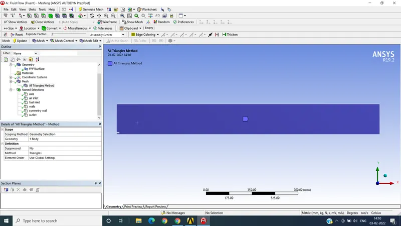
2) In meshing section , there is provided the proper names , air inlet , fuel inlet , axis , walls , symmetry wall and outlet. given meshing with applying methods with triangular shapes of meshing on it , having mesh elements sixes of 4mm,
nodes = 29873
elements = 58618 which is in limits with license .
all meshing body and all edges is attached . we consider the 2d body for simulations for fast and accurate results . such meshing is suitable , if we use 3d body it become too complex and elements sizes increses, which results in solution failure.
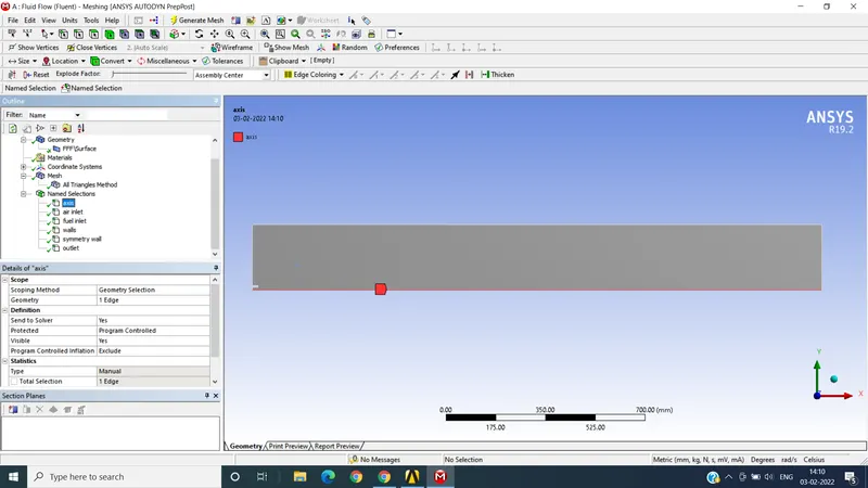
AXIS WITH X AXIS
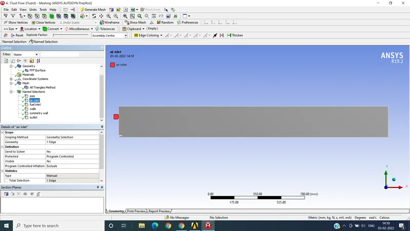
AIR INLET
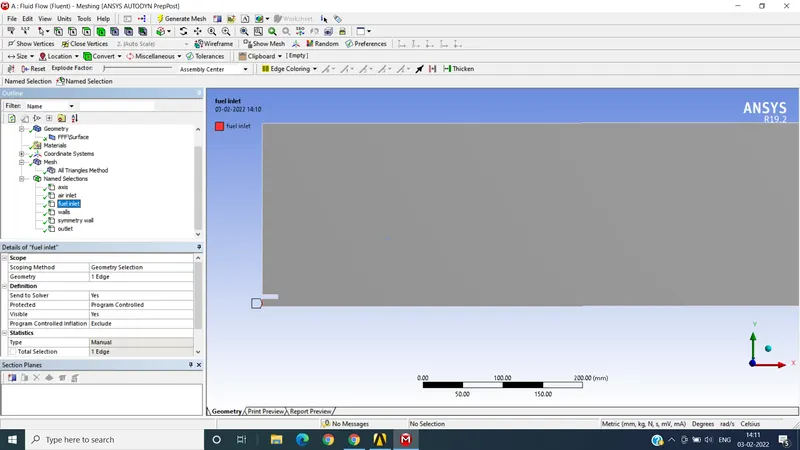
FUEL INLET SECTION
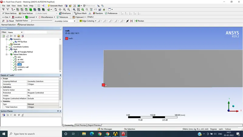
WALLS
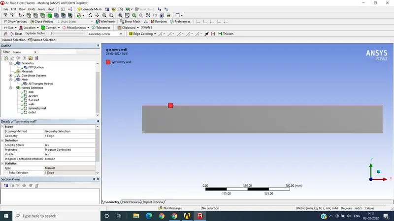
SYMMETRY WALL
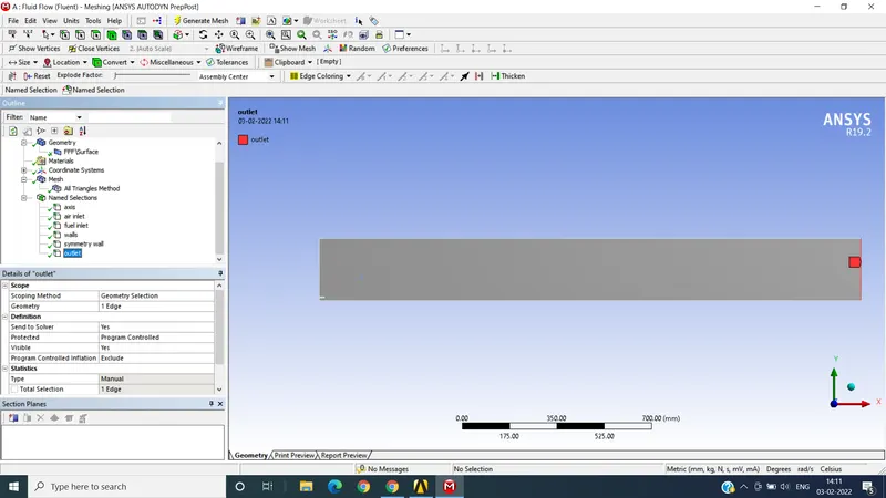
OUTLET
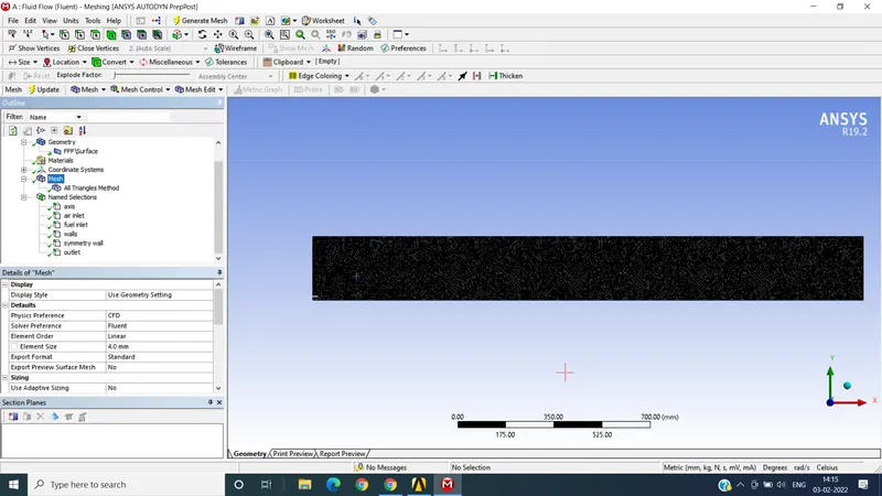
MESHING SHOWING NAMES AND SIZE
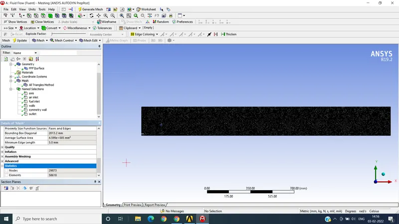
MESHING SHOWING NUMBER OF NODES AND ELEMENTS.
3) IN FLUENT SECTION , We enable the enery equations for solutions , and then we enable the k-epsilon section with standard wall functions as attached.
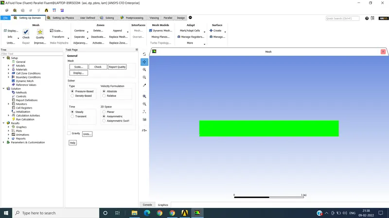
showing axis symmatry
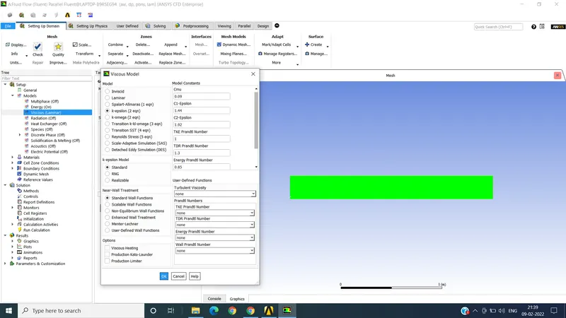
showing k-epsilon
after such activation we move to important part on SPECIES.
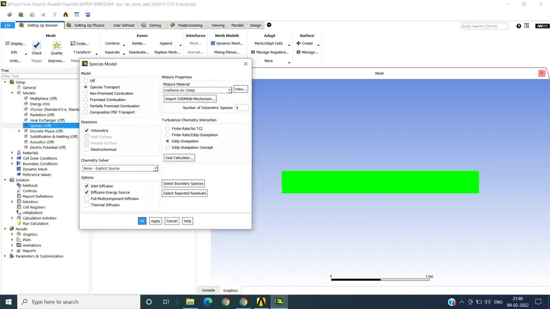
as given in picture , species transport is activated , with volumetric enabling, and inlet and diffusion energy source is activated with , methane -2step selecting , enabling the eddy dissipation .
then in sub section of species . we go to NOX section as shown in figure
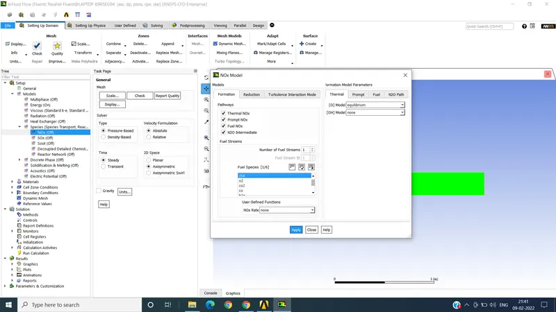
in NOX section we enable all 4 section , thermal NOX, prompt NOX, fuel NOX and N2o intermidiate , then we give fuel stream CH4 for fuel species . applying to it ,
then we go for SOOT particals
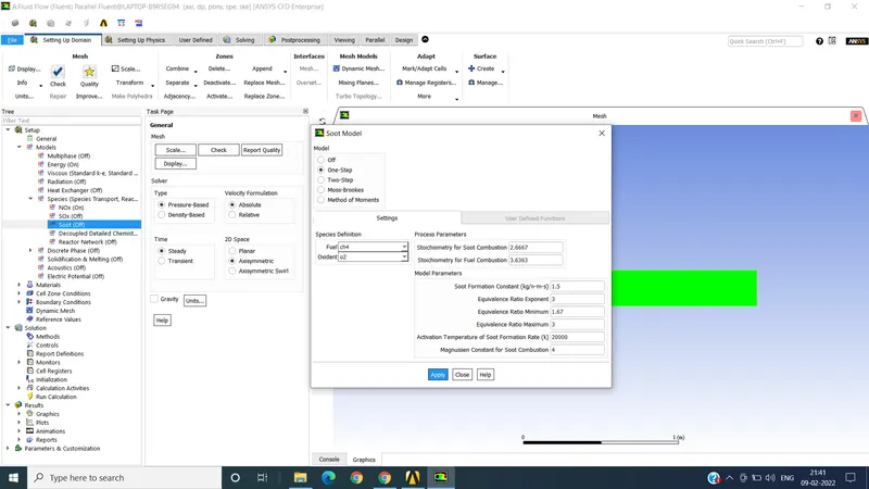
we enables one step in soot model , and for fuel add CH4 and for oxidant for O2 for air section for cumbustion, as discussed above for smooth cumbustion we need proper fraction of fuel and air. such takes the details/ calculate and give results of soot particals , during conbustions .
after that we go for material section and we get directly methane-air-2step for material , after than we go for
boundry zone , we select the air inlet for giving velocity , v=0.8 m/s , and in species section we give for air inlet haveing mass fraction of O2 is 0.23 as shown in figure
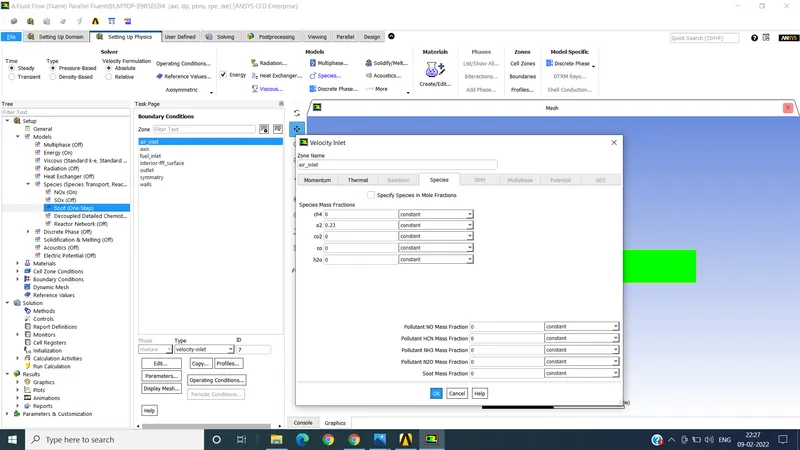
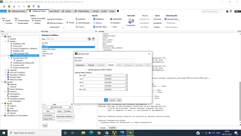
for fuel inlet we took velocity is 80 m/s and temperature is 300 k , and for species initially we not consider the water H2O with CH4 , only methane is consider , as shown in figure .
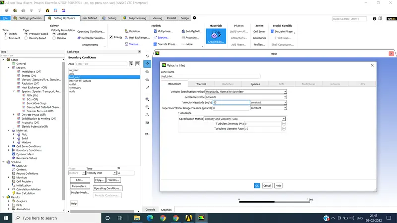
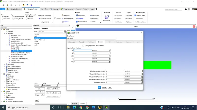
as we know mass fraction of methane is consider 1 , fuel consider in 1 ratio of methane and 0.23 of O2 and not consider nitrogen which is included in atmospheric air .some fraction is taken by nitrogen .
next we check the outlet sections it should we consider pressure outlet for it respectively.
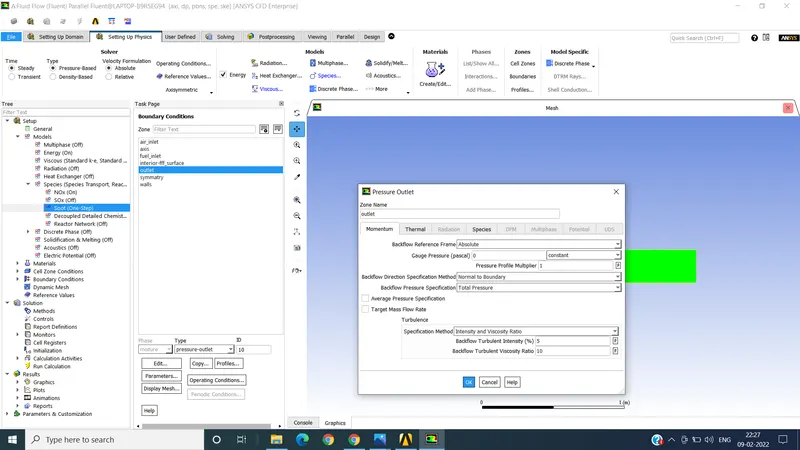
after completing the species section of zones we go for run clculatons as giving iteration of 1000 ,as attached
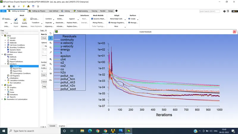
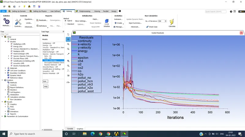
as shown from residual curve the solution is converged .
after this we go in result section , we take the conture after taking all sections of body and getting results of pressure temperature , velocity, CH4, CO, CO2, H2o, NO, N2O, NOX and soot particals .
we add 6 line , line 1, line 2, line 3, line4 , line 5 and line 6 , at specified distances
for line 1 distance is x=100 and y=230 mm
for line 2 distance is x=200 and y=230 mm
for line 3 distance is x=500 and y=230 mm
for line 4 distance is x=1000 and y=230 mm
for line 5 distance is x=1500 and y= 230 mm
for line 6 distance is x=1800 and y=230 mm.
then we add chart for creating and ploting this all 6 line , we add all 6 line and changing the line with respecte to y axis .
all resutls is attached .
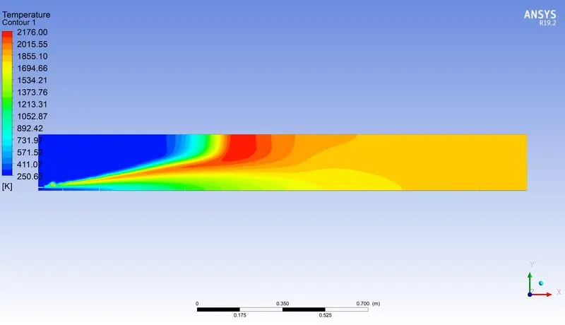
temperature conture
line chart for all line
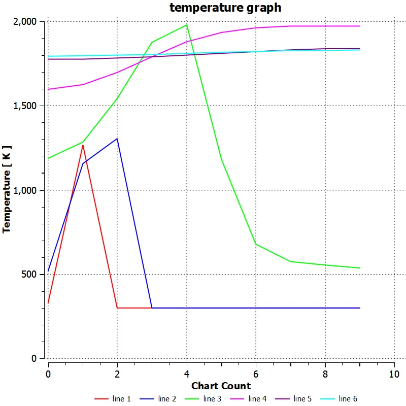
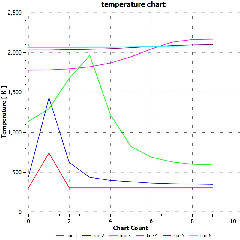
as we observed from chart , temperature at line 1 is at low and at line 3 temperature rises to maximum aprox 2000k and reduce along with it , and line 5 and 6 at the end section of chamber we see the temperature is high at initial level and remains less fluctuated .
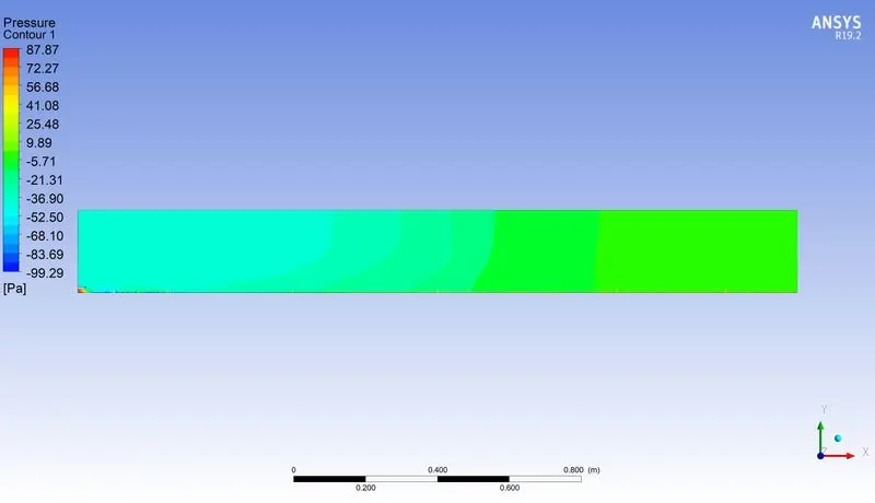
pressure conture
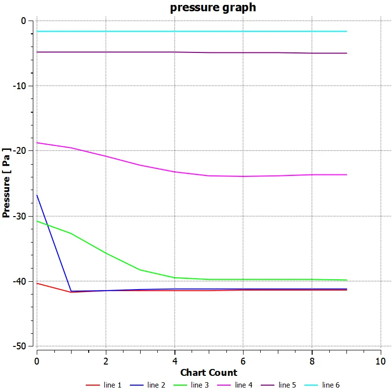
pressure line chart
velocity conture
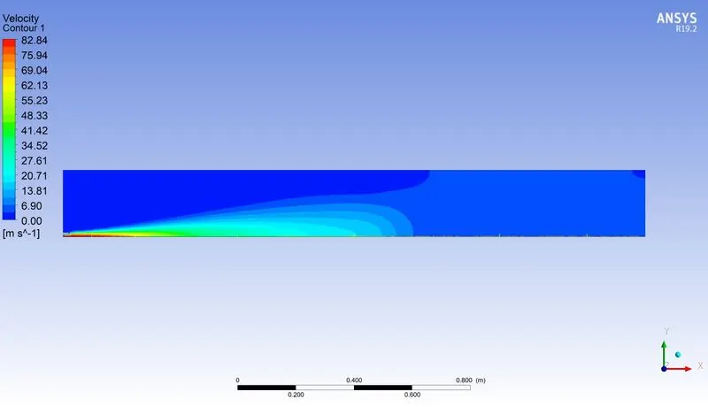
velocity line gne graph at different sections
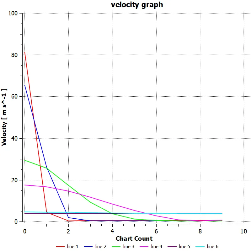
initially as shown from line chart the velocity at inlet air and fuel section is more reduces drastically after combustions the is due to fuel inlet velocity is very high , which cause proper mixing with the inlet air , which result in better efficiency .and at the end section line 5 and 6 has similar velocity and lower then mid line and initial lines .
CH4 mass fractions conture
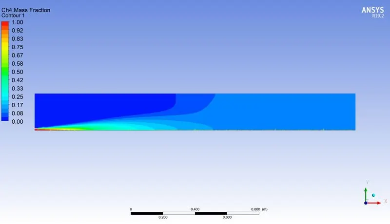
line charts of ch4 at each sections
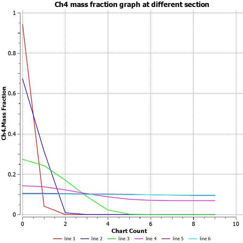
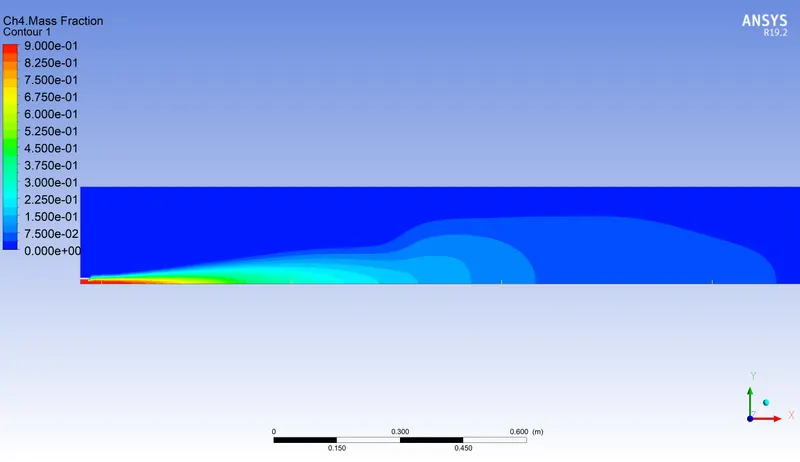
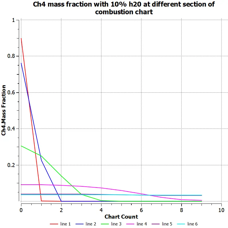
as shown in line chart the ch4 mass fraction is maximum at line 1 and line 2 , but as we go along the x axis ch4 mass fraction is reduce drastically due to combustion takes place .. and at remains constant at line 1,2 and three.
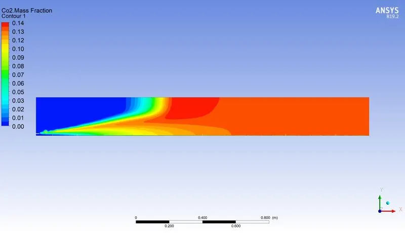
CO2 mass fraction conture is attached
line chart for CO2 at different sections
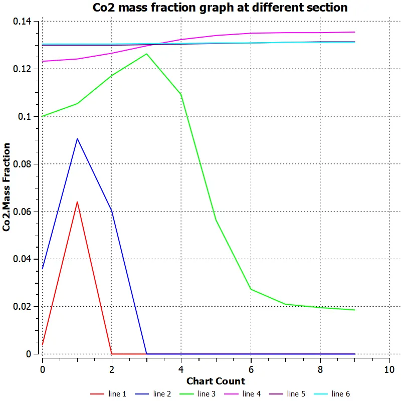
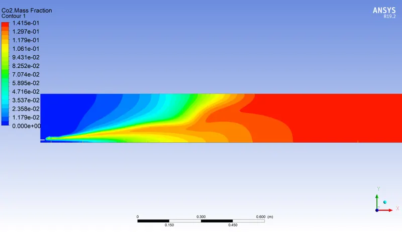
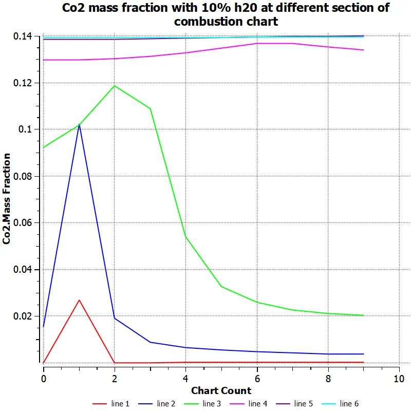
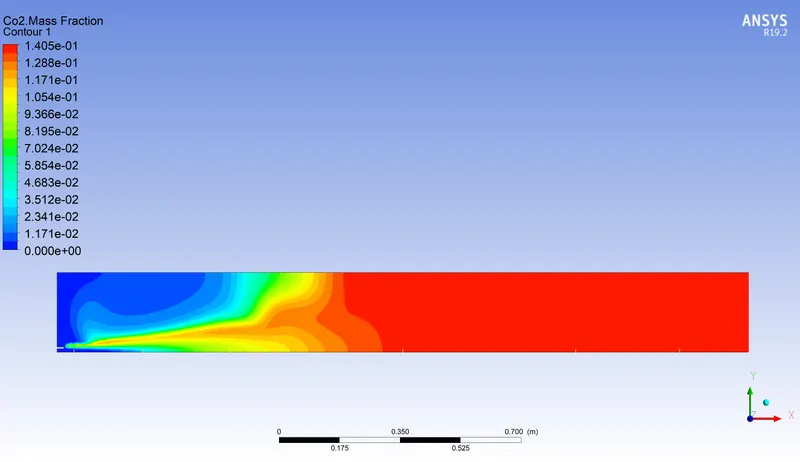
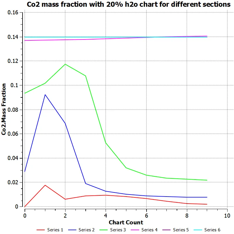
initially there is less co2 and after combustions thre is high co2 , line 5 and 6 have more co2 .
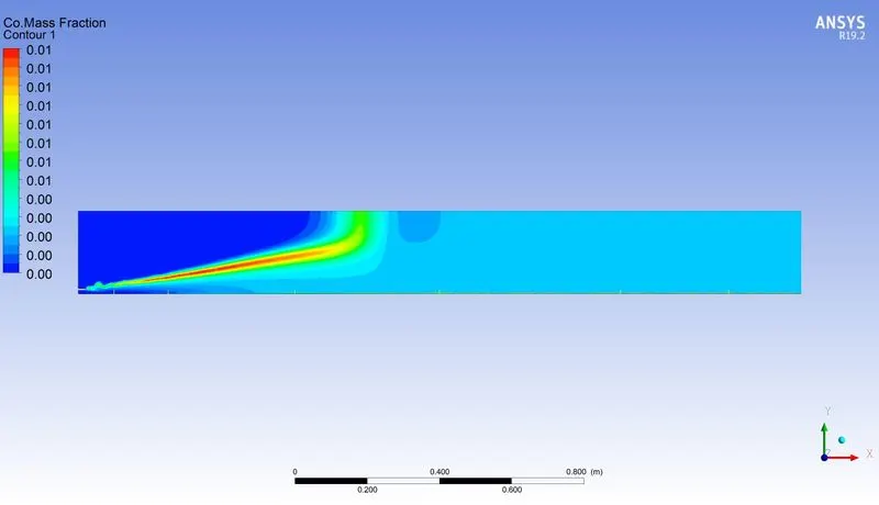
CO mass fraction conture and line chart is attached
Oxygen O2 mass fraction conture with line chart at different section is attached
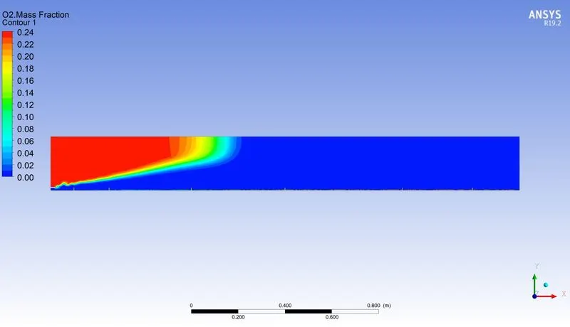
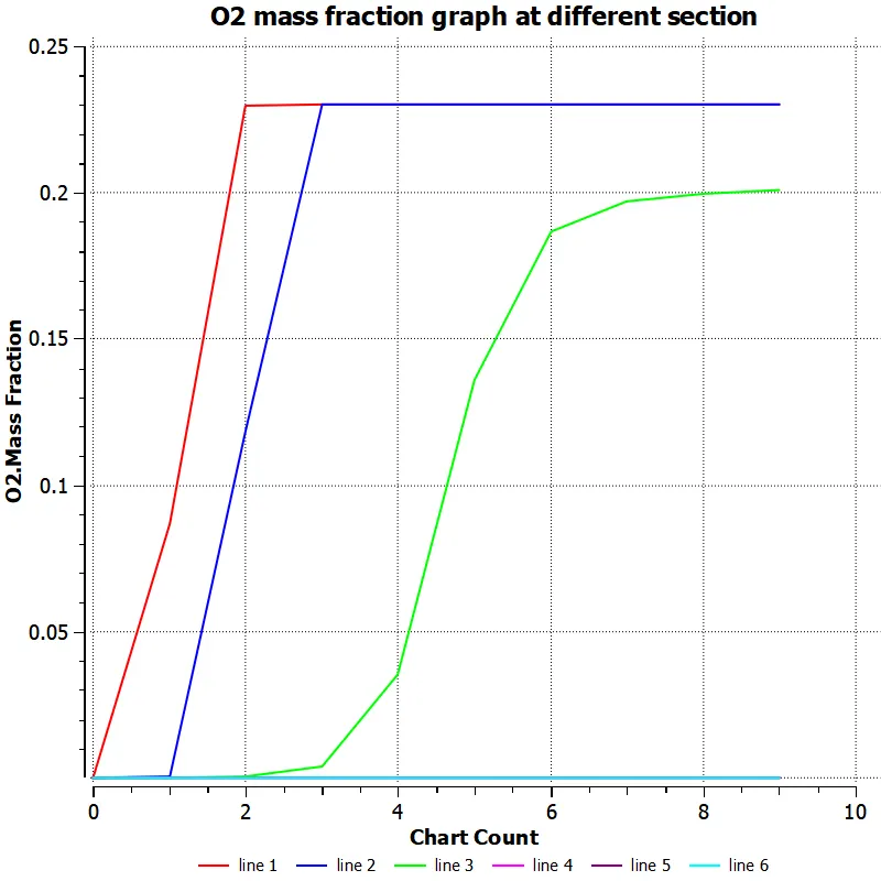
as shown from oxygen graph and conture , inlet air has fully o2 and after combustion thre is no o2 is remain in combustion chamber section, line 1 and 2 has mass fraction of o2 is very high but after certion point o2 remains constant due to constant ration of o2 and in line 5 and 6 thre is no o2 is present it totally burned with the fuel .
H2o mass fraction conture and chart for different sections
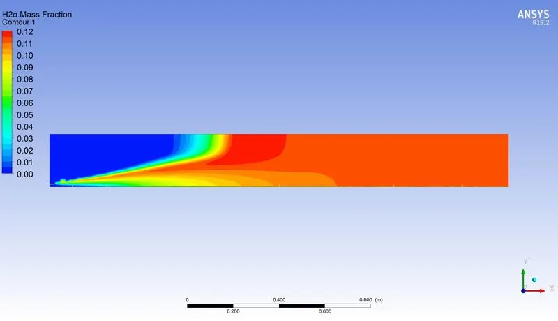
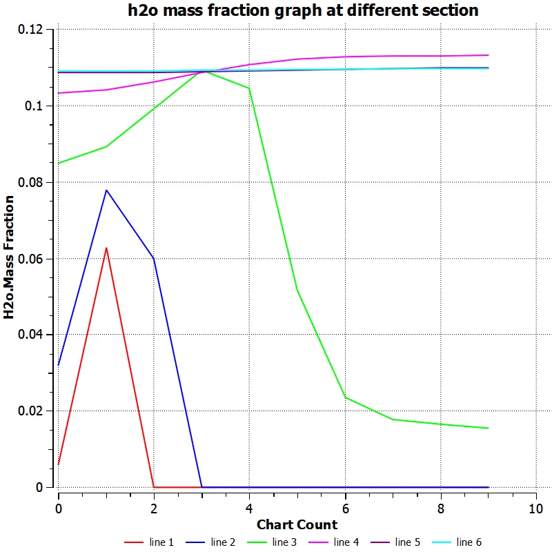
as shown from line chart at each sections pf h2o mass fractions at initial section thre is no fractions of h2o is presents but at mid and end section is increses due to combustions , it has very less amount of h2o is present in it , if we do not provide the water in air inlet sections , this is due to chemical reaction takes place at the time of combustions which cause to creat the very less mass fraction of h2o.
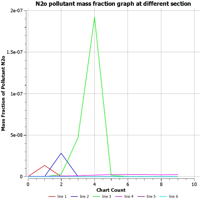
N2O MASS FRACTION AND GRAPH FOR EACH SECTIONS
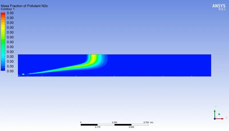
N2 mass fractions with line chart at each sections
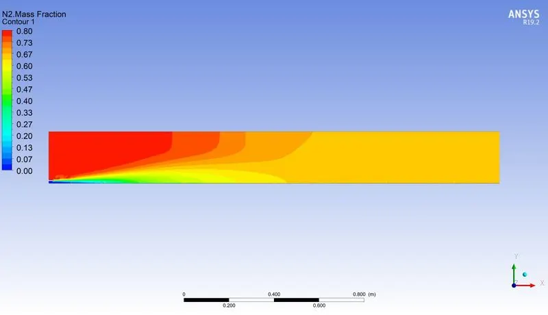
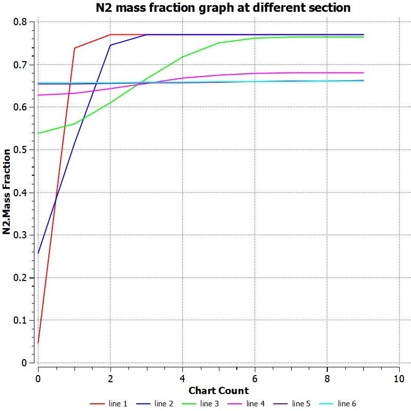
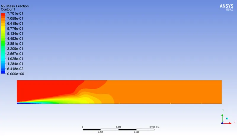
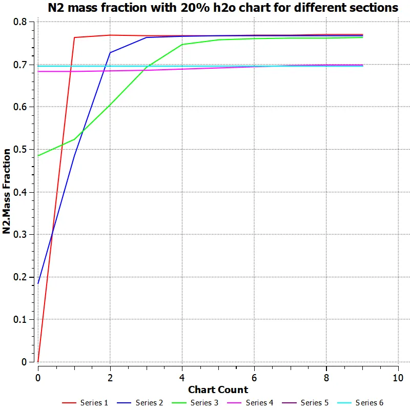
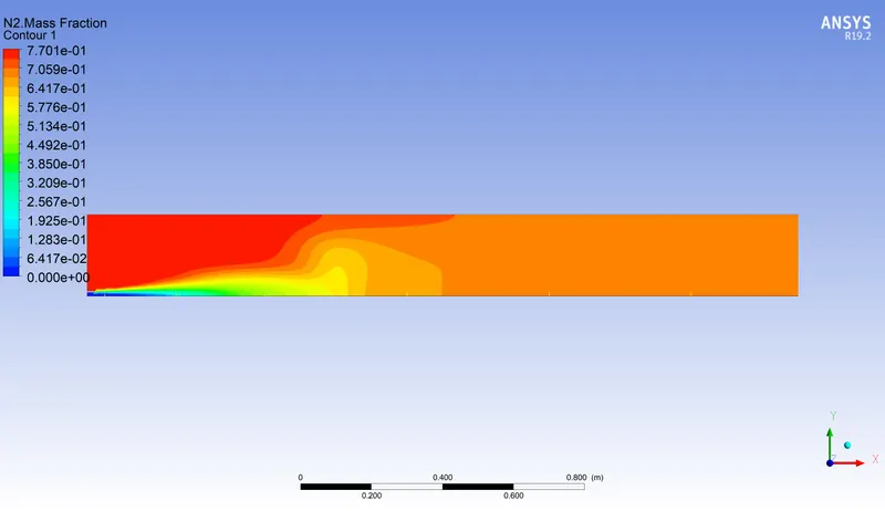
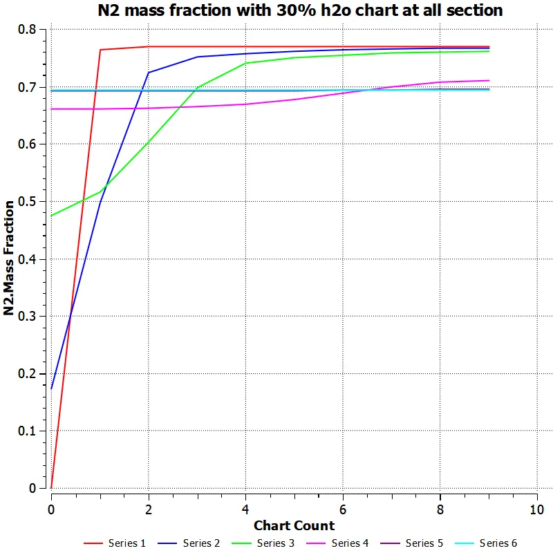
initially there is very less N2 mass fraction is present and at mixing and combustion section it increases rapidly due to reaction takes place and it remains constant at end sections at line 4, 5 and 6 .
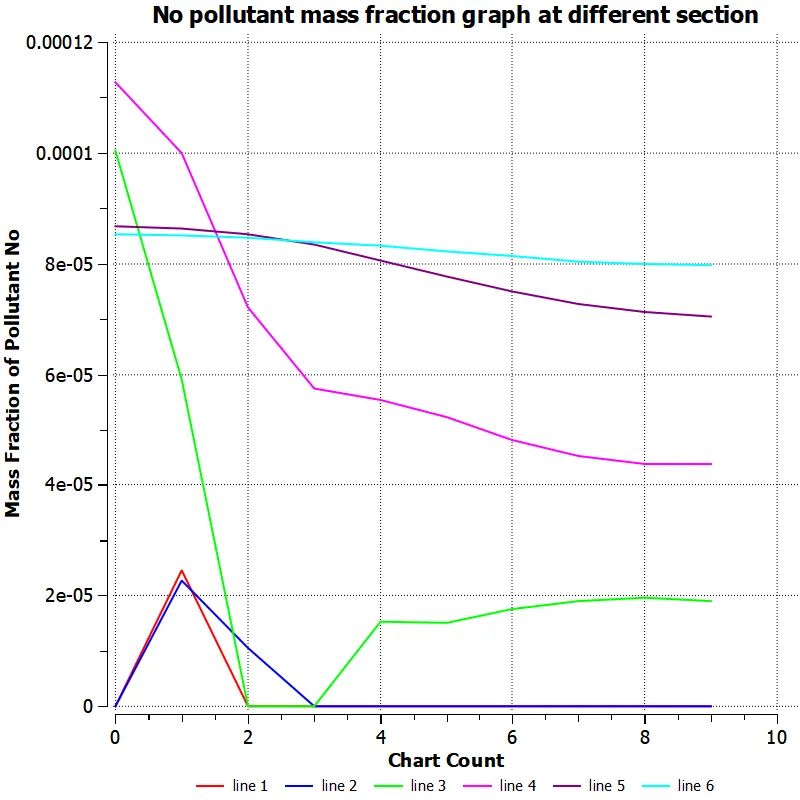
NOx pollutant mass fraction conture and chart shownig the each sections of it
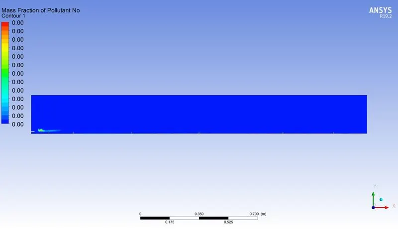
soot pollutant mass fractions and line chart at each sections .
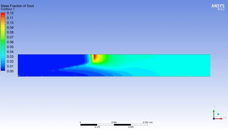
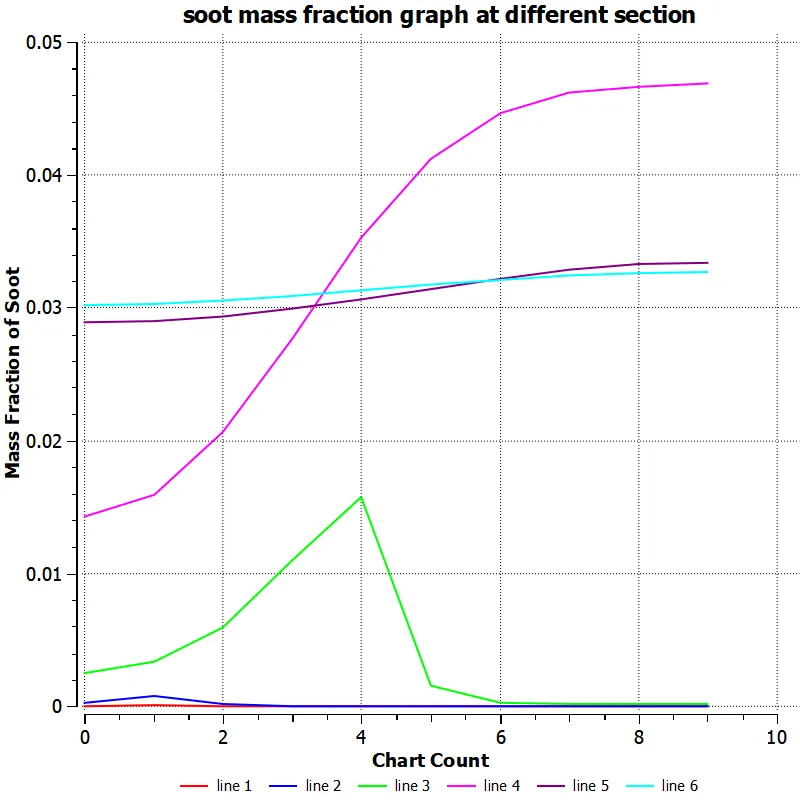
as shown from both pollutant NOX and soot it shows the results at at the mid and end sections of chamber
it has nigligible at initial but as the combustion proces starts its increses rapidly , at the mid pint at line 4 we see the soot partical is maximum and little reduces in some section at line 5 and 6 .
PART 2
As we know in part 1 we did not add the water in air but in part 2 we add water h2o as
10% h20 with ch4 , and ch4 =0.90 , h20 =0.10
20% h20 with ch4 , and ch4 =0.80 , h20=0.20
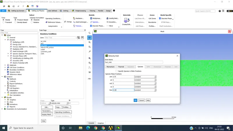
and 30% h2o with ch4 and ch4 =0.70 and h20 =0.30 accondingly . the detials of adding is attached .
residual curve for results
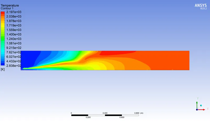
ALL RESULTS OF 10% OF WATER H2O IS ADDED WITH CH4
Temperature conture of 10 % water mixed with ch4
graph for line at different sections of combustion chambers
CH4 MASS fraction conture and line chart
CO2 MASS FRACTION AND LINE CHART
O2 MASS FRACTION AND LINE CHART
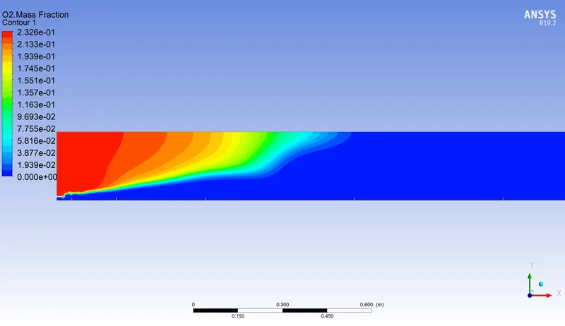
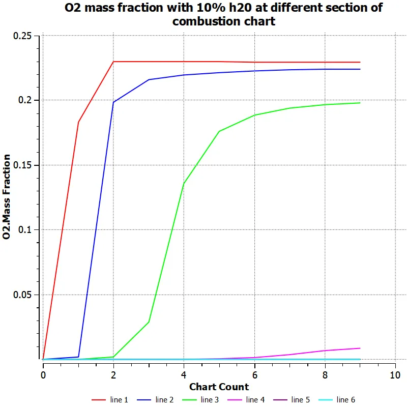
N2 MASS FRACTION AND LINE CHART
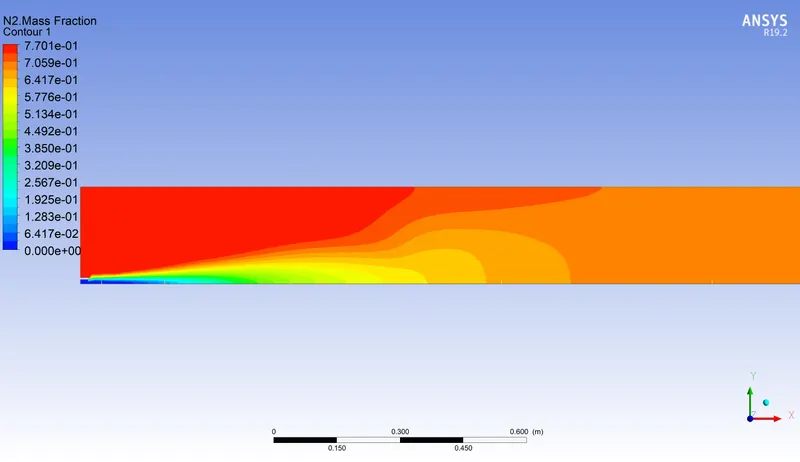
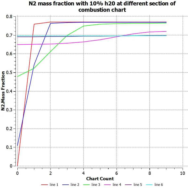
H20 MASS FRACTION AND LINE CHART
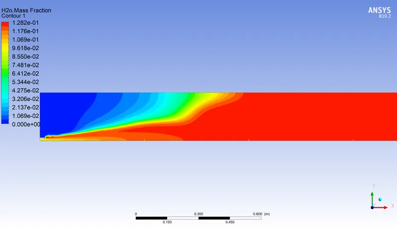
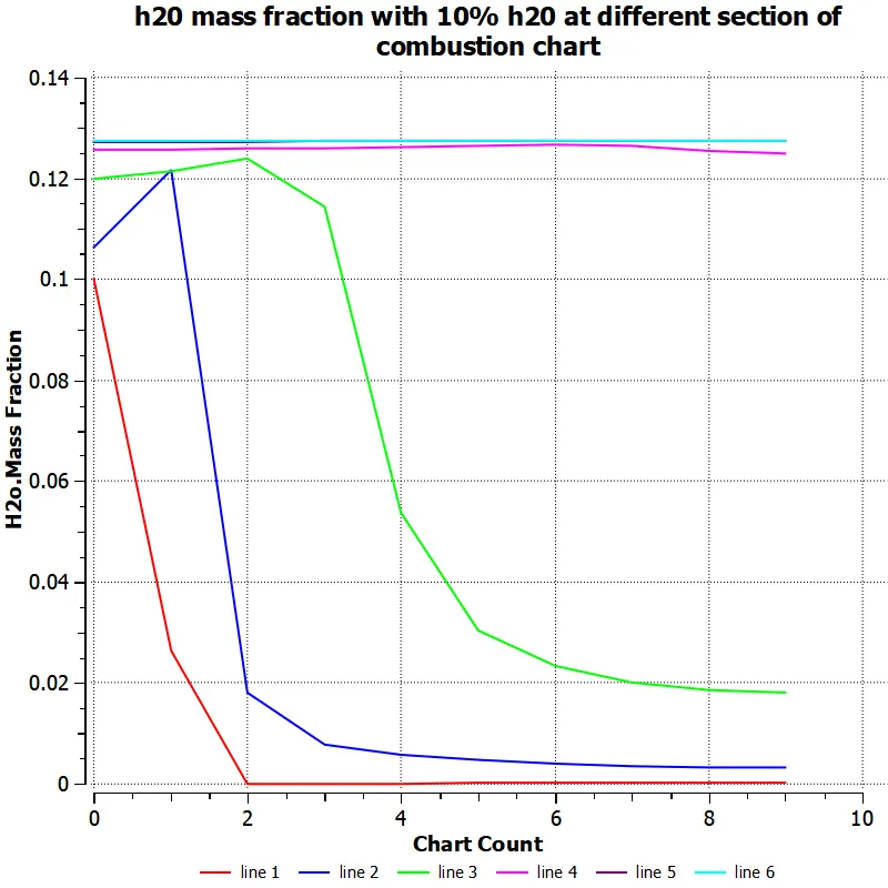
as we show from above conture we see h2o mass fraction is initially presents with the fuel ch4 shown by line 1 ,2 and 3 , but we se the fraction of mass increses at the time of combustion and after and remaons constant at section 5 and 6 , this because combustion added more fraction of h2o .
NO POLLUTANT MASS FRACTION WITH LINE CHART IS ATTACHED
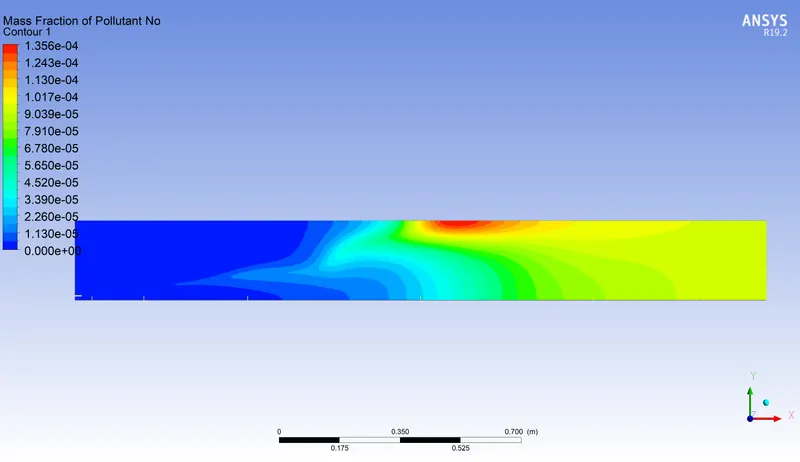
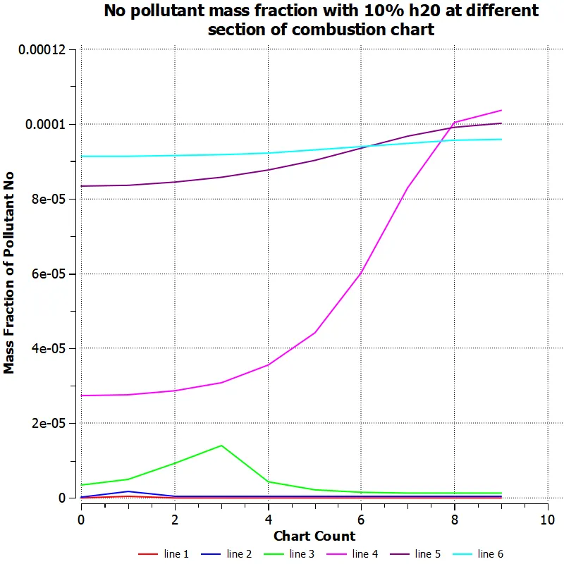
SOOT POLLUTANT MASS FRACTIONS WITH LINE CHART OF ALL SECTIONS
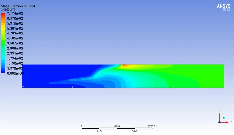
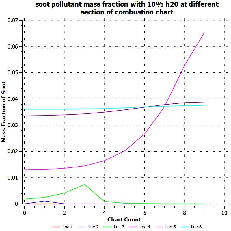
FOR 20% ADDED H20 WITH CH4
ALL RESULTS IS ATTACHED
TEMPERATURE CONTURE WITH LINE CHART
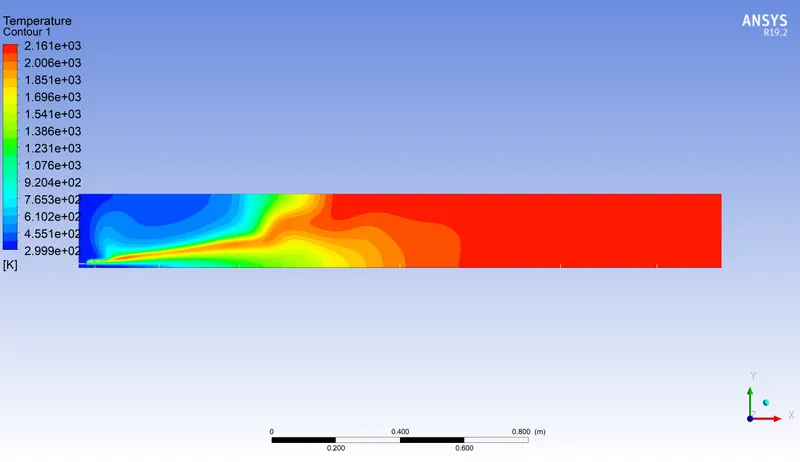
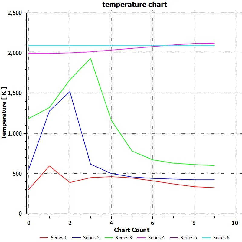
CH4 MASS FRACTION CONTURE AND LINE CHART
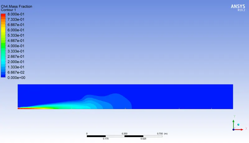
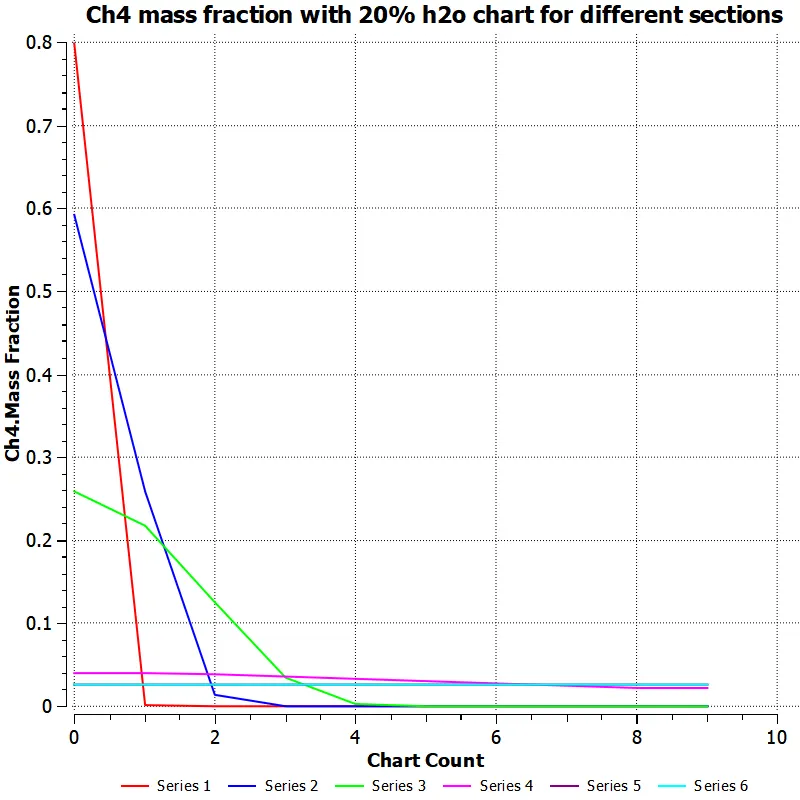
O2 MASS FRACTION CONTURE AND LINE CHART
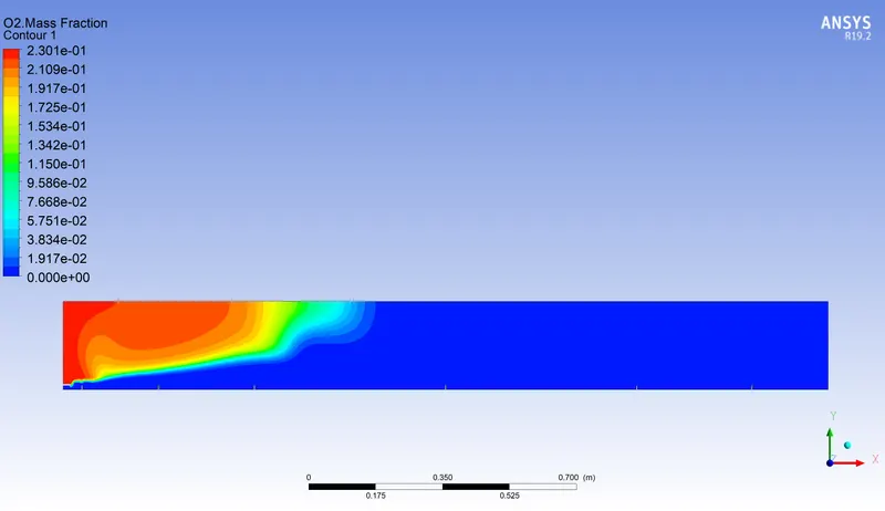
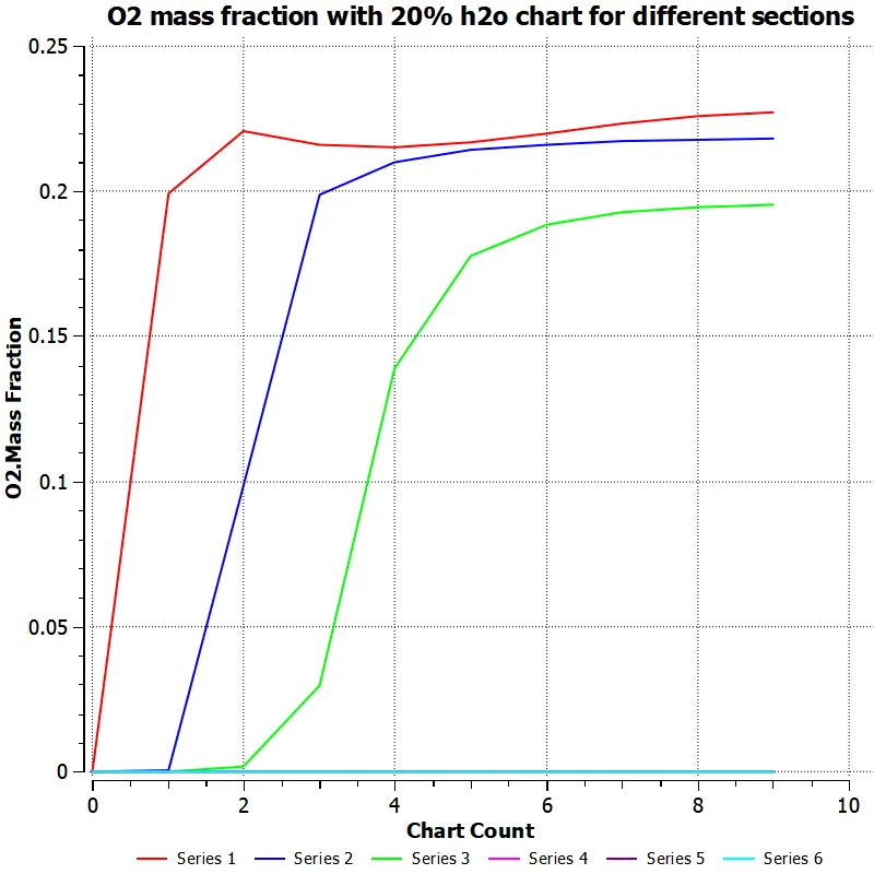
CO2 MASS FRACTION CONTURE AND LINE CHART
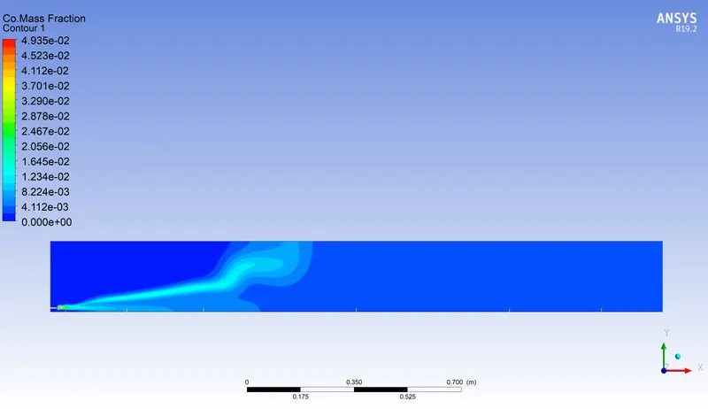
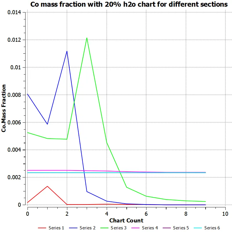
CO MASS FRACTION CONTURE WITH CHART
N2 MASS FRACTION CONTURE AND LINE CHART
NO POLLUTANT CONTURE AND LINE CHART
FOR 30% OF H20 IS ADDED WITH CH4 MASS FRACTION
RESULTS IS ATTACHED
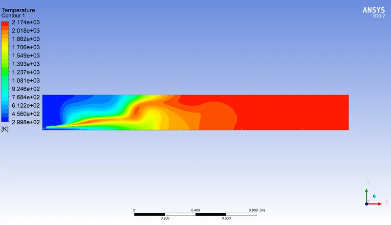
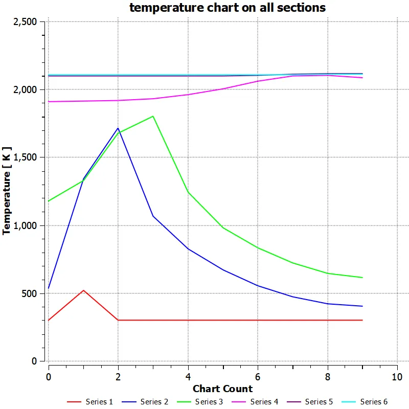
TEMPERATURE CONTURE AND LINE CHART SHOWING TEMPERATURE FLUCTATION IN EACH SECTIONS
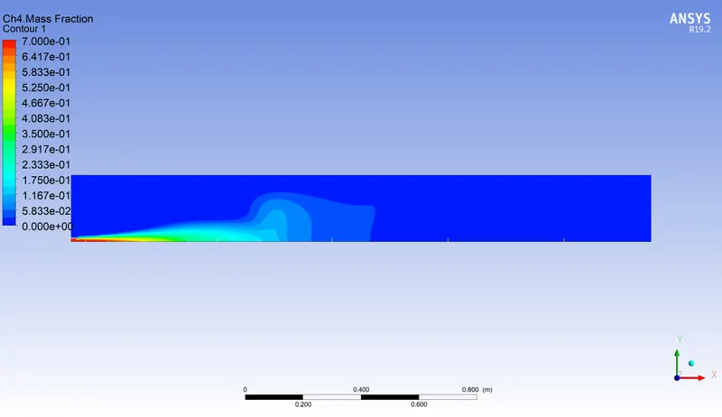
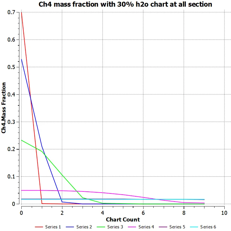
CH4 MASS FRACTION AND LINE CHART FOR EACH SECTIONS IS ATTACHED
O2 MASS FRACTION AND LINE CHART OF EACH SECTIONS
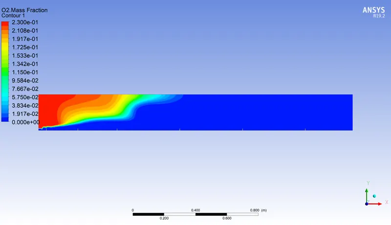
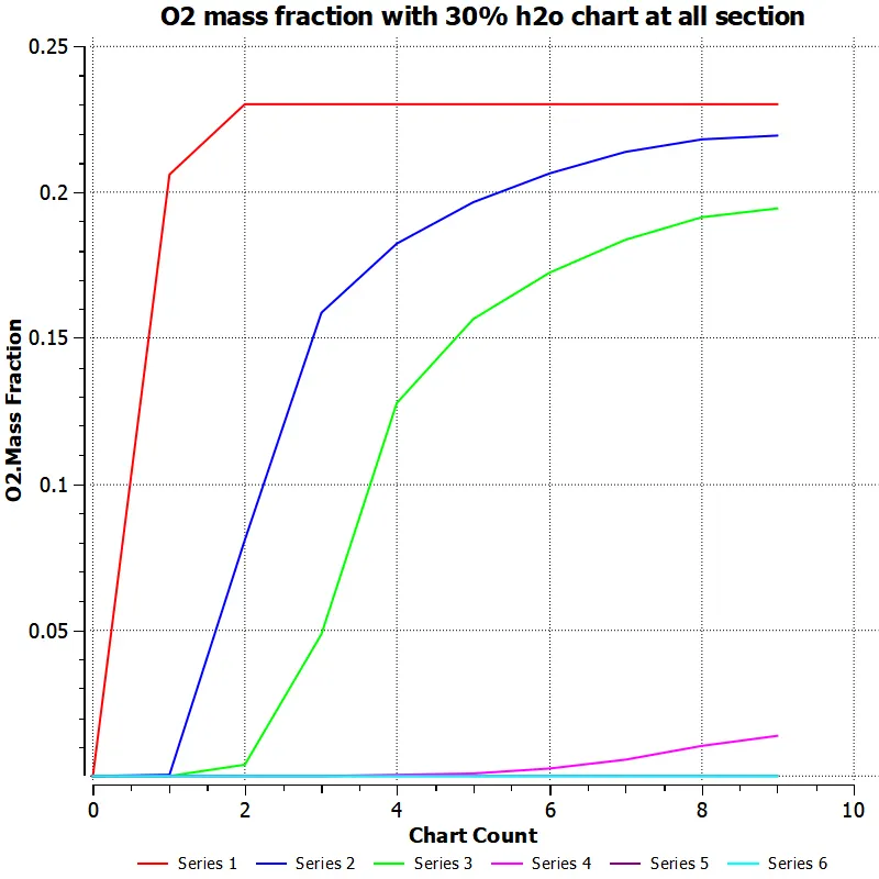
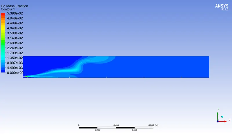
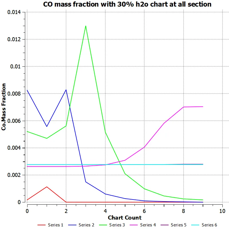
CO MASS FRACTION AND LINE CHART
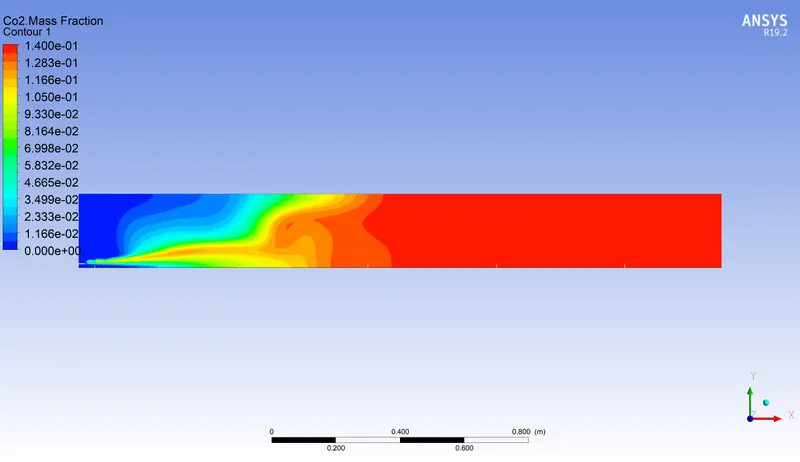
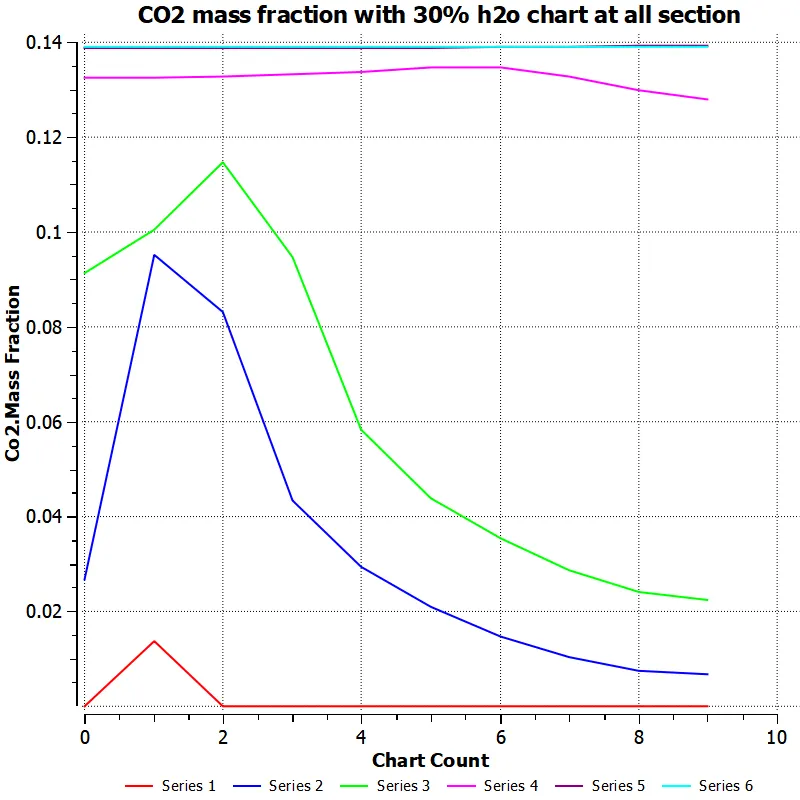
CO2 MASS FRACTION AND LINE CHART FOR ALL SECTIONS
N2 MASS FRACTION WITH AND LINE CHART
NO POLLUTANT MASS FRACTION AND LINE CHART
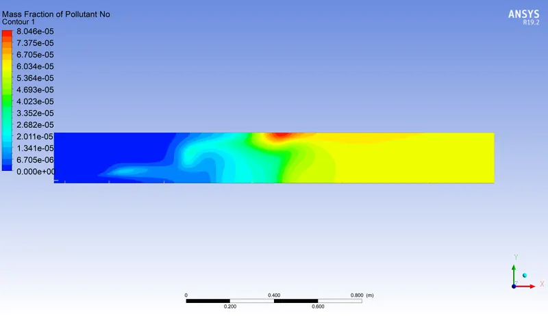
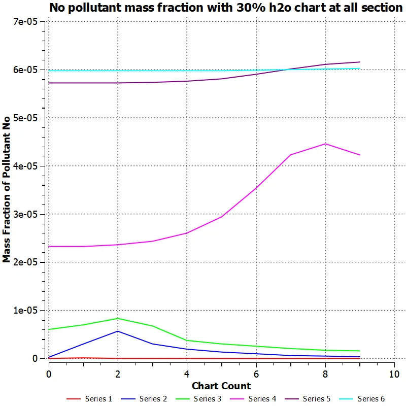
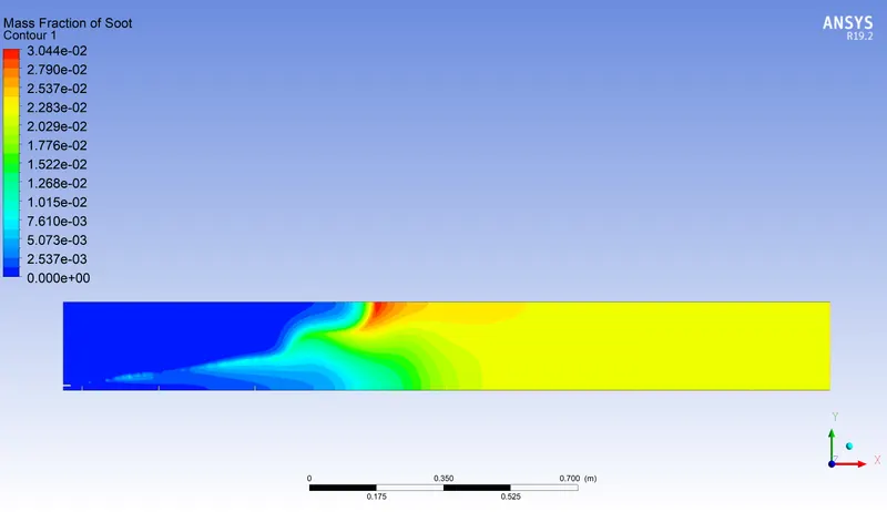
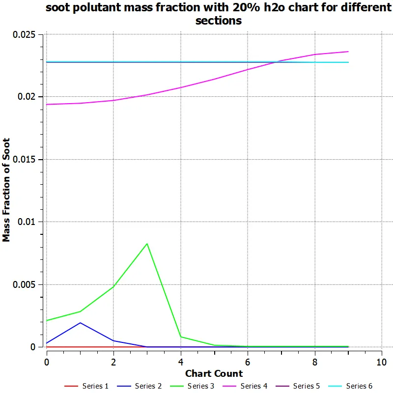
SOOT POLLUTANT CONTURE AND LINE CHART DIAGRAM AT EACH SECTION
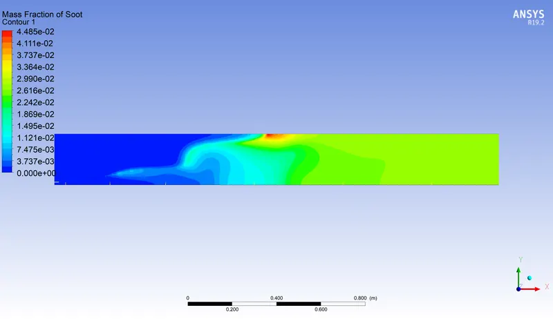
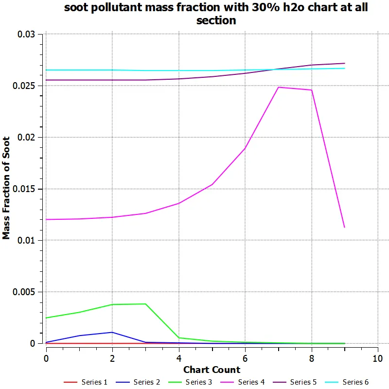
Aa shown all results for 10% , 20 % and 30 % of h2o with ch4 which gives following results .
| sr no | % of h20 contains | CH4: H2O RATIO | Nox mass fraction | SOOT mass fraction | highest temperature |
| 1 | 10% | 0.90 : 0.10 | 1.356 e-4 | 7.174 e -2 | 2197 |
| 2 | 20% | 0.80 : 0.20 | 6.915 e-5 | 3.044 e-2 | 2161 |
| 3 | 30% | 0.70 : 0.30 | 8.046 e-5 | 4.485 e-2 | 2174 |
| 4 | no h20 | 1 | 0.000118 | 0.12 | 2176 |
Inference:
from the above plots and results we observed that Nox ans Soot particals is reduced when we increases the fraction of water h2o in methane air mixture. when the is added the h20 in the fuel which is delay the combustion , and which cause the proper and accurate mixing of fuel and air which cause to increase in efficiency , due to which results in reduction of nitrogen oxides and there is no oxygen is remains behind after combusitons , no reaction will happen with the nitrogen.
soot is formed as a result of burning of fuels in presences of less oxygens and low temperature , as complete combustion takes places due to efficient mixing of air and fuel , so there is very small amount of fuel and oxygen is present in it , which reduces the formation of soot partical in combustion chamber.
CONCLUSION
1) with the increase in mass fraction of water h2o in fuel air mixture which results of reduction of NOx after combustion
2) with the increse in mass fraction of water h2o in fuel air mixture which results in reduction of soot partical formation in combustion chamber ,
3)with the increase of mass fraction of water with fuel air mixture which results in increase the efficiency of combustion.
4) whith the increase in mass fraction of water in fuel air mixture which results in reduction in temperature at combustion section .
5) with increase in mass fraction of water with fuel air mixture which results in reduction in velocity at exhaust section of combustion.
6) we uses the 2d section of combustion for calculating and anlysis which gives the results very fast and accurate instead we use 3d model for analysis , which also cause for time reduction for results and reduce the cost and time of anslysis . which is important aspect in industry .
7) we can increase the fraction of water upto certain point , beyond certain point more fraction of h2o causeing the reduction of combustion temperature which causes the efficiency of combustion.because the change in temperature is vital important in combustion calculations .