Week 10: Project 1 - FULL HYDRO case set up (PFI)
Introduction
PFI engine mixing fuel with air in the carburetor before it entered the combustion chamber was still the main technology being used in gasoline vehicles
PFI engines use a three-way catalytic converter, exhaust sensors, and computer-controlled engine management to constantly adjust the fuel-to-air ratio injected into each cylinder
CI8H18 is fuel is almost equal to gasoline fuel
Converge Setup
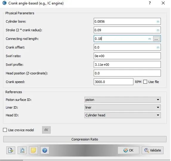
Engine Geometric Parameters
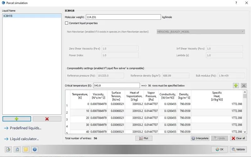
Parcel simulation
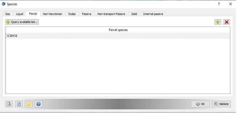
Species
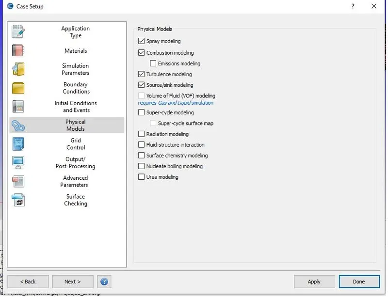
Define
Boundary conditions
Piston temperature - 450K
Liner temperature - 450K
Head temperature - 450K
Spark Plug temperature - 550K
Spark Plug electrode temperature - 600K
Exhaust ports temperature - 500K
Exhaust outflow - 1 bar
Exhaust outflow temperature - 800k
Exhaust species concentration
| Stoichiometric calculation | ||||
| Species | moles | MW(g/mol) | Mass | Mass Fraction |
| Co2 | 8 | 44.01 | 352.08 | 0.192304 |
| H2O | 9 | 18.01528 | 162.1375 | 0.088559 |
| N2 | 47 | 28.0134 | 1316.63 | 0.719137 |
| Total | 1830.847 | 1 | ||
Exhaust valve top temperature - 525K
Exhaust valve angle temperature - 525K
Exhaust valve bottom temperature - 525K
Intake port - 1 temperature 425K
Intake port - 2 temperature 425K
Inflow pressure - 1 bar total pressure
Inflow temperature - 363K
Inflow species - Air
Intake valve top temperature - 480K
Intake valve angle temperature - 480K
Intake valve bottom temperature - 480K
Region & Initialization
- Cylinder
- Pressure - 1.85731 bar
- Temperature - 1360K
- Stoichiometric composition
- Intake port - 1 (closer to combustion chamber)
- ic8h18 - 0.025508
- o2 - 0.20157
- n2 - 0.77292
- Temperature - 390k
- pressure - 1 bar
- Intake port - 2 (away from combustion chamber)
- Air
- Temperature - 370K
- Pressure - 1 bar
- Exhaust
- Pressure - 1.85731 bar
- Temperature - 1360K
- Stoichiometric composition
Case setup
Injection Parameters
Time & Temperature
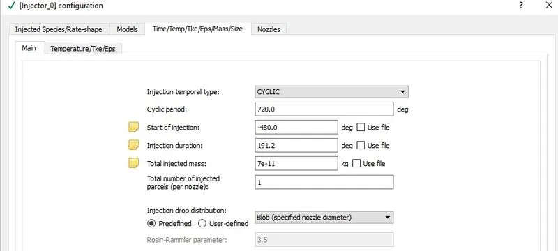
- Fuel flow rate = 7.5e-4 Kg/second
- Injection start time = -480.0
- Injection duration = 191.2
- Fuel temperature = 330K
Spark Ignition Parameters
- Start of spark = -15 deg
- Spark duration = 10 deg
- Spark location = -0.003 0 0.0091
- Spark radius = 0.0005m
spray model
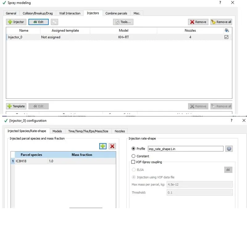
Profile
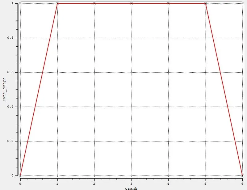
Spray Plot analysis

Extracting values
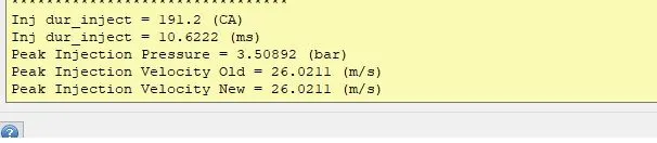
Nozzle positions and parameters
Nozzle diameter = 250 micro-meter
Circular injection radius = Nozzle radius
Spray cone angle = 10
- Nozzle 0
- center 0.0823357 0.00100001 0.07019
- Align Vector -0.732501 0.210489 -0.647408
- Nozzle 1
- center 0.0823357 -0.00099999 0.07019
- Align Vector -0.732501 -0.210489 -0.647408
- Nozzle 2
- center 0.0823357 -0.0004 0.07019
- Align Vector -0.5 -0.2 -0.647408
- Nozzle 3
- center 0.0823357 0.0003 0.07019
- Align Vector -0.5 0.2 -0.647408
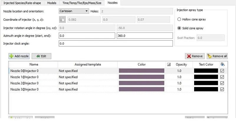
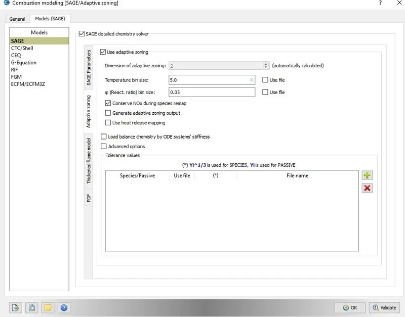
Combustion modeling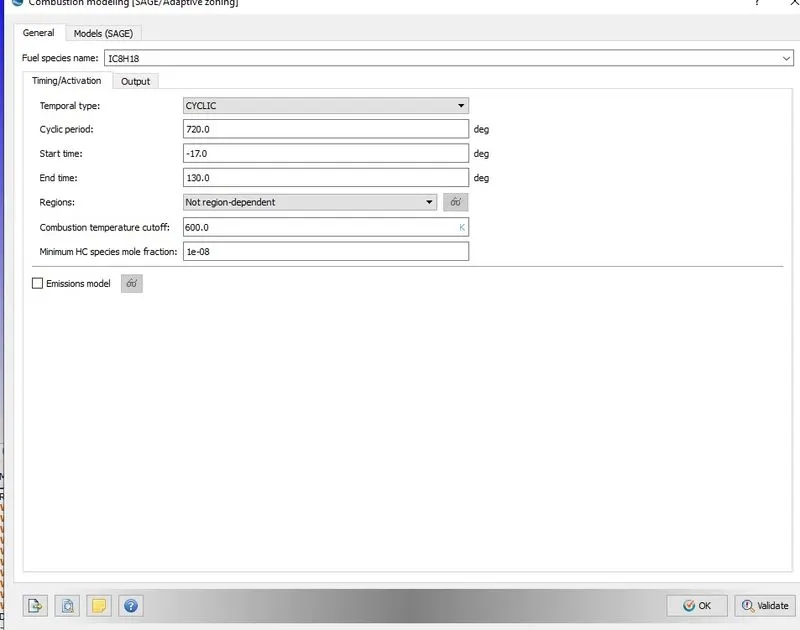
models
Embedded Setup
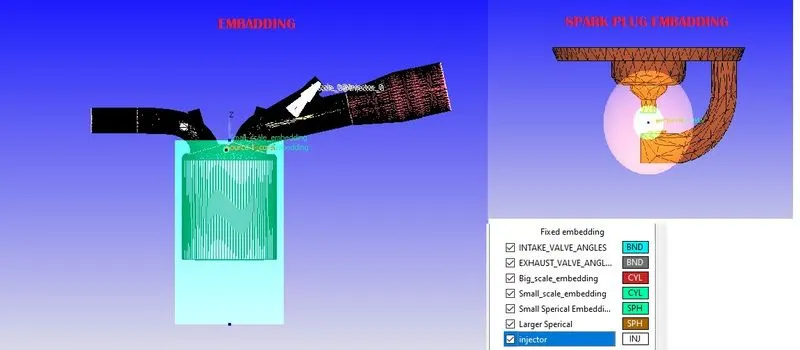
for refinement embedded in spark plug, cylinder, injector
AMG Time scale
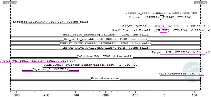
which clearly shows AMG Timing at the combustion stage
Adaptive Mesh
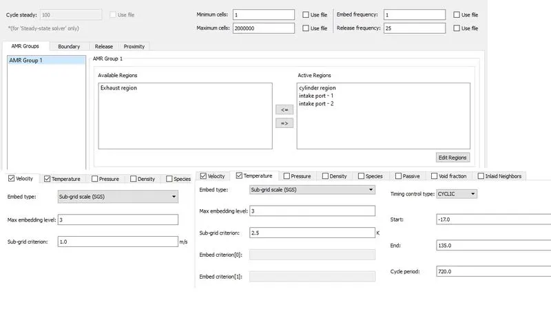
Adaptive mesh assign for both velocity and temperature value for better result output
SOURCE SETUP
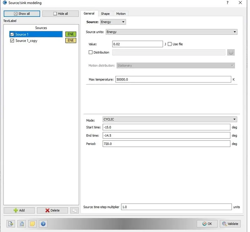
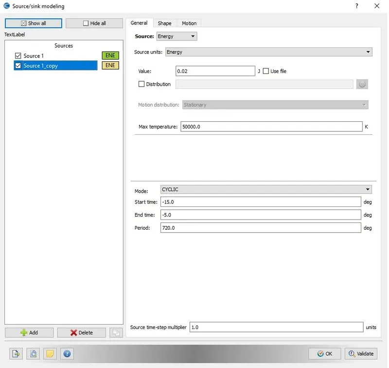
2. Why do we need a wall heat transfer model? Why can't we predict the wall temperature from the CFD simulation
actually, we are giving a guess value for the initial state (p*) for boundaries from the combustion the initial value will change to combustion wall heat transfer model if it is not the result will not be realistic this clearly state Conjugated Heat Transfer Model (CHT) this wall heat transfer result from different Boundaryues are studied and manipulate for engine life (i.e- for cooling of the engine like a radiator)
Result
Conversion of result
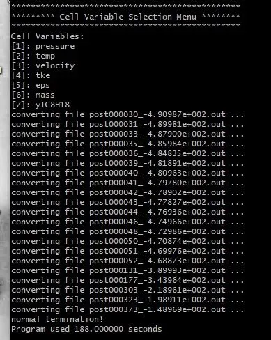
Working mode setup output
Section view
above clearly define the region and refinement near sparkplug & AMG refinement
Graphs
Pressure
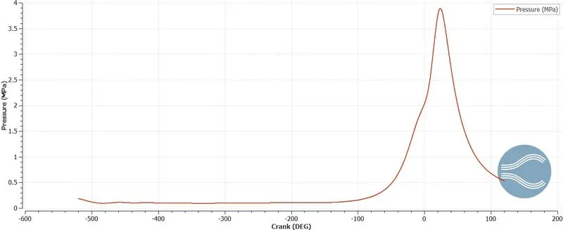
maximum pressure at approximately at 30 degrees P=3.85MPA
Temperature
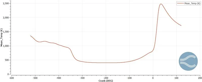
maximum Temperature 2500 k at 30 degree
Heat Release Rate
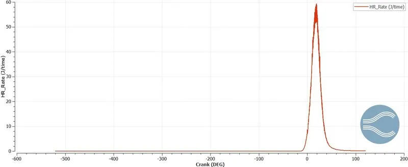
maximum heat release Rate 59 J/s with a 30degree crank angle
Mass Of Fuel
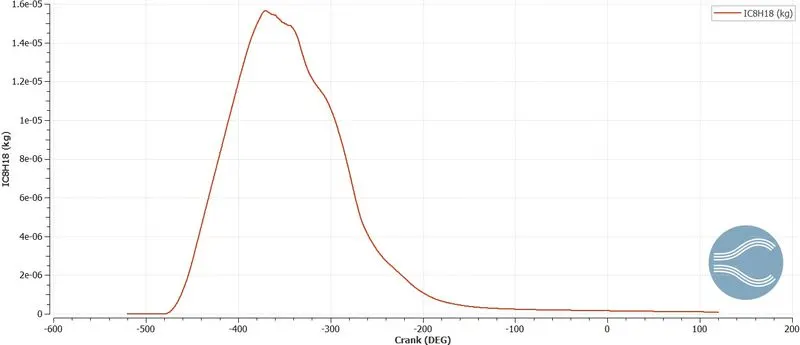
fuel spray starts at-530 degrees to -100 degrees where peak fuel spray at -440 degrees
CO2
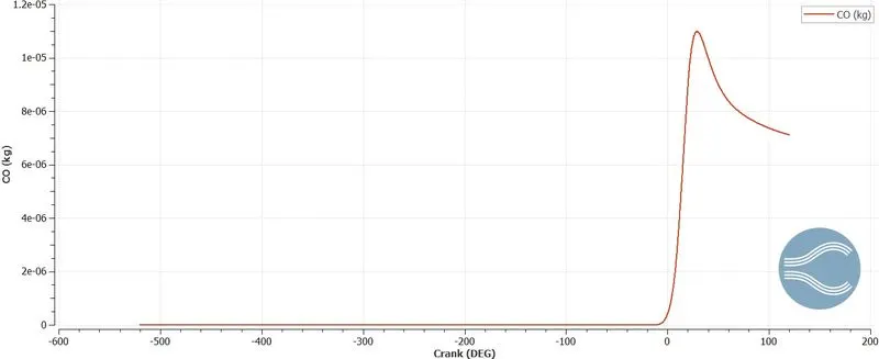
o to 30-degree combustion start there is a sudden increase in Co2 and reducing after cmbustion
engine performance Calculation
Formula
Compression ratio
Compression ratio= maximum volume/ minimum volume
Volume vs Crank angle
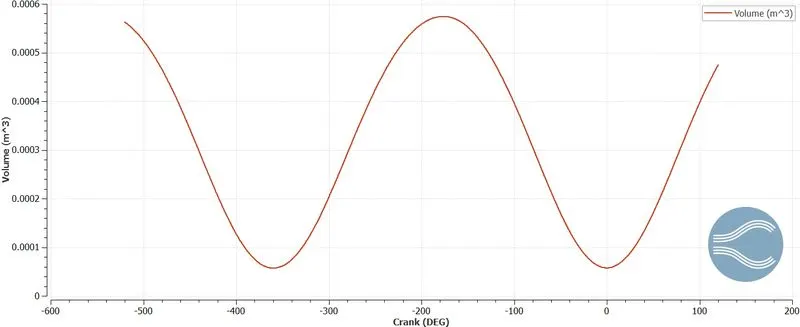
from graph extracted
V_min=5.754e-5 m3
V_max=0.000574215 m3
combustion efficiency
Integrated Heat release Rate
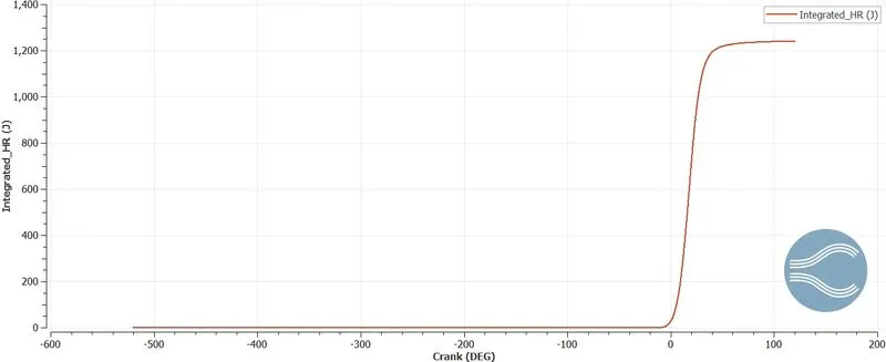
`eta=`Total Heat Release rate/ Total energy of fuel
The Total Heat Release rate is calculated from the graph in maximum Integrated Heat Release
max_IHR=1241 j
Total energy of fuel= mass of fuel*Lower Heat Value (LHV)
LHV=44.78e6 J/kg which is obtained from IC8H18
Torque
power=(work done/time)
In Engine performance calculator
apply
- Bore =0.086 m
- Stroke = 0.09 m
- to get the value of engine performance

Duration of combustion=240.12 deg
combustion timing=5.55e-5 s
from that, we can calculate the power
Torque
from power `P=(2*pi*N*T)/60`
`T=(P*60)/(2*pi*N)`
Python
"""
Engine Performance calculation
Program by Jagaveerapandiyan
"""
import numpy as np
#min & max volume
V_min=5.754e-5
V_max=0.000574215

#compression ratio
r=V_max/V_min
print('Compression_ratio=',r)

#Engine efficiency
max_IHR=1241 #j
#IC8H18
LHV=44.78e6 #J/kg
#mass of fuel
mf=3e-5 #kg
#Total energy of fuel
TF=mf*LHV
print('Total energy of fuel=',TF,'j')

#combustion efficiency
c_eff=(max_IHR/TF)*100
print('combustion efficiency=',c_eff)

#Torque
N=3000 #rpm
WD=464.646 #Nm
#combustion timing
td=5.55e-5 #s
#Duration of combustion
D=240.12
ct=D*td
#power (workdone/time)
P=WD/ct
print('Power=',P,'W')
#Torque from P=2*pi*N*T/60
T=P*60/(2*np.pi*N)
print('Torque=',T,'Nm')
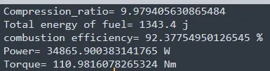
Values
5. the significance of ca10, ca50, and ca90
CA is the combustion of different percentages (fuel burn)
CAD10 is 10% of combustion at 6.83717 degree
CAD50 is 50% of combustion at 18.4632 degree
CAD90 is 90% of combustion at 31.701 degree
From this, we can easily locate combustion crank angle function properties change in the combustion chamber
Conclusion
The study of the PFI engine has been analyzed and engine characteristics is studied using converge and find out maximum work done= 468.64 Nm at 240.99 with respective Torque is calculated as T=110.98 Nm with 92.37% combustion efficiency